EP0420689B1 - Dispositif pour la manutension de gazon - Google Patents
Dispositif pour la manutension de gazon Download PDFInfo
- Publication number
- EP0420689B1 EP0420689B1 EP90310678A EP90310678A EP0420689B1 EP 0420689 B1 EP0420689 B1 EP 0420689B1 EP 90310678 A EP90310678 A EP 90310678A EP 90310678 A EP90310678 A EP 90310678A EP 0420689 B1 EP0420689 B1 EP 0420689B1
- Authority
- EP
- European Patent Office
- Prior art keywords
- turf
- roll
- chassis
- laying
- machine
- Prior art date
- Legal status (The legal status is an assumption and is not a legal conclusion. Google has not performed a legal analysis and makes no representation as to the accuracy of the status listed.)
- Expired - Lifetime
Links
- 238000000034 method Methods 0.000 claims description 4
- 238000002485 combustion reaction Methods 0.000 claims description 2
- 238000005096 rolling process Methods 0.000 claims 1
- 230000007246 mechanism Effects 0.000 description 11
- 230000001360 synchronised effect Effects 0.000 description 6
- 244000025254 Cannabis sativa Species 0.000 description 3
- 230000007423 decrease Effects 0.000 description 2
- 230000008439 repair process Effects 0.000 description 2
- 230000000284 resting effect Effects 0.000 description 2
- 239000002689 soil Substances 0.000 description 2
- 230000008859 change Effects 0.000 description 1
- 239000004927 clay Substances 0.000 description 1
- 230000006835 compression Effects 0.000 description 1
- 238000007906 compression Methods 0.000 description 1
- 230000014509 gene expression Effects 0.000 description 1
- 238000003306 harvesting Methods 0.000 description 1
- 230000007935 neutral effect Effects 0.000 description 1
- 239000003415 peat Substances 0.000 description 1
- 230000002093 peripheral effect Effects 0.000 description 1
- 230000008569 process Effects 0.000 description 1
- 238000004804 winding Methods 0.000 description 1
Images




Classifications
-
- A—HUMAN NECESSITIES
- A01—AGRICULTURE; FORESTRY; ANIMAL HUSBANDRY; HUNTING; TRAPPING; FISHING
- A01G—HORTICULTURE; CULTIVATION OF VEGETABLES, FLOWERS, RICE, FRUIT, VINES, HOPS OR SEAWEED; FORESTRY; WATERING
- A01G20/00—Cultivation of turf, lawn or the like; Apparatus or methods therefor
- A01G20/10—Pre-cultivated sod or turf; Apparatus therefor
- A01G20/18—Apparatus for laying sods or turfs
-
- A—HUMAN NECESSITIES
- A01—AGRICULTURE; FORESTRY; ANIMAL HUSBANDRY; HUNTING; TRAPPING; FISHING
- A01G—HORTICULTURE; CULTIVATION OF VEGETABLES, FLOWERS, RICE, FRUIT, VINES, HOPS OR SEAWEED; FORESTRY; WATERING
- A01G20/00—Cultivation of turf, lawn or the like; Apparatus or methods therefor
- A01G20/10—Pre-cultivated sod or turf; Apparatus therefor
- A01G20/12—Apparatus for cutting sods or turfs
-
- Y—GENERAL TAGGING OF NEW TECHNOLOGICAL DEVELOPMENTS; GENERAL TAGGING OF CROSS-SECTIONAL TECHNOLOGIES SPANNING OVER SEVERAL SECTIONS OF THE IPC; TECHNICAL SUBJECTS COVERED BY FORMER USPC CROSS-REFERENCE ART COLLECTIONS [XRACs] AND DIGESTS
- Y10—TECHNICAL SUBJECTS COVERED BY FORMER USPC
- Y10S—TECHNICAL SUBJECTS COVERED BY FORMER USPC CROSS-REFERENCE ART COLLECTIONS [XRACs] AND DIGESTS
- Y10S111/00—Planting
- Y10S111/901—Lawn or turf
-
- Y—GENERAL TAGGING OF NEW TECHNOLOGICAL DEVELOPMENTS; GENERAL TAGGING OF CROSS-SECTIONAL TECHNOLOGIES SPANNING OVER SEVERAL SECTIONS OF THE IPC; TECHNICAL SUBJECTS COVERED BY FORMER USPC CROSS-REFERENCE ART COLLECTIONS [XRACs] AND DIGESTS
- Y10—TECHNICAL SUBJECTS COVERED BY FORMER USPC
- Y10S—TECHNICAL SUBJECTS COVERED BY FORMER USPC CROSS-REFERENCE ART COLLECTIONS [XRACs] AND DIGESTS
- Y10S414/00—Material or article handling
- Y10S414/124—Roll handlers
Definitions
- This invention relates to an apparatus for laying turf and more particularly to such an apparatus comprising a chassis; carrying and conveying means mounted on the chassis for carrying a roll of turf; propelling means to which said chassis is mounted for driving the chassis in a forward direction over a ground surface at a driving speed at which the turf is to be laid; synchronising means for synchronising the conveying means and the propelling means, thereby to synchronise the laying of the turf substantially with the driving speed.
- Turf is typically harvested and rolled in small rolls (approx. 1 m2) by a harvesting machine (an example of which is disclosed in EP-A-0221745) and is transported to the site where the turf is to be laid. The turf is then laid manually.
- This laying process is time consuming and labour intensive, and hence turf laying machines for laying large rolls of turf have been proposed.
- One example of such a machine is disclosed in AU-B-537118.
- This document describes a turf cutting and laying machine which, when laying turf, is in the form of a frame which is attached to a suitably modified tractor, and which frame is towed therebehind.
- Turf is laid behind the tractor by unrolling a roll of turf contained in the frame. This is not desirable as the tracks created by the tractor are substantial, and compress the earth. This causes the laid turf to be uneven and disrupts the previously prepared ground on which the turf is to be laid.
- EP-A-0178081 Another example of a large roll turf laying machine is disclosed in EP-A-0178081.
- This document discloses a machine which carries a roll of turf on a frame at its front and which is unwound by means of a control roller. This roller rotates against the exterior of a turf roll to cause it to rotate and hence unwind.
- This approach is flawed, as the control roller is too small to be able to propel the heavy turf and may instead cut through the turf.
- the fact that the machine drives over the turf as it is laid creates the possibility that any weaknesses in the turf, which are commonplace, will be subjected to unnecessary stress and may cause the turf strip to break.
- US-A-4084763 discloses a machine for handling artificial turf in which machine a friction drive roller contacts the circumferential surface of the roll of artificial turf to feed out the same. This arrangement is satisfacotry for artificial turf but would suffer from similar problems to those discussed hereinabove in relation to EP-A-0178081 in the unlikely event that it was used for laying natural turf.
- the present invention aims to provide a machine which will lay adjoining, or at least adjacent, pre-cut strips of natural turf (sods) to form a substantially even covering of turf on a predetermined prepared area of ground.
- an apparatus of the above mentioned type as known from EP-A-0178081 being characterised by the carrying and conveying means being arranged to contact in use a substantial portion of the circumferential surface of the roll of turf at the underside thereof in order to rotate the roll so as to cause the roll to be unwound, and to convey the turf toward the ground surface behind the propelling means, which substantial portion extends from both sides of a notional plane that is substantially perpendicular to the chassis and includes the axis of the roll of turf.
- a presently preferred embodiment of the invention is a self-propelled vehicle comprising a chassis that generally is run on tracks or rollers and can be steered.
- the machine will lay a rolled strip of grass or other turf which is mounted to, and carried by, the machine.
- the rolled strip of grass or other turf may be carried by a bobbin or spindle in the form of a shaft or drum.
- a preferred machine has a mounting or supporting frame that is located at the top thereof and upon which a roll of turf that is to be laid is rotatably supported by a bobbin or spindle. Means are provided by which a supported roll of turf can be driven independently of the speed of movement of the machine over the ground so that one end of the roll of turf can be fed to an output mechanism of the machine whilst that machine is stationary relative to its surroundings.
- a mechanism may be provided by which both full rolls of turf, and empty spindles or bobbins, can be loaded onto, and removed from, the machine.
- This mechanism may be a winch, lifting frame or other means.
- a motor that is preferably but not essentially an internal combustion engine, is provided together with gearing that will provide at least one reverse, transit, and one forward, laying, speed of drive to ground-engaging tracks.
- a roller may be provided which will press the turf strip into engagement with the ground as the turf is fed outwardly from a guide mechanism of the machine.
- An oscillating rake, rotating cultivator or other mechanism may be mounted on the vehicle to remove and/or repair any marks, footprints or the like that either the vehicle itself or its operator may make during a turf laying operation.
- a pivotally mounted plate, lever or the like may be provided to measure continuously the amount of turf remaining on any roll and to supply this information in a form in which it can be read mechanically or electronically by a drive synchronisation unit of the machine, so that the speed at which turf is supplied for laying on the ground at any instant will always substantially match the speed of travel of the machine itself over the ground at the same instant.
- Means may be provided by which the laying mechanism can be lowered into operative engagement with the ground or be moved upwardly entirely out of engagement with the ground.
- Indicating means may be provided to enable an operator manually to follow a string or like guide, or the edge of a previously laid strip of turf.
- Such indicating mechanism may be constructed for linking to the steering mechanism of the machine so as substantially automatically to control that steering mechanism whereby the machine will automatically, or semi-automatically, follow a guide or the edge of a previously laid strip of turf.
- the invention also extends to a method of laying turf as claimed in claim 17.
- Rotation of the turf roll is synchronised to the speed of travel of the machine over the ground by the turf roll drive unit 15 through a system of mechanical, hydraulic or electrical gears.
- the unit 15 may comprise oppositely directed conical input and output members drivably interconnected by a belt or the like, the position of the latter being continuously governed axially of the two cones by the diameter of the turf roll at any instant.
- the speed of movement of the strip 1a will change accurately to match the substantially constant speed of "laying" travel of the machine as the turf roll being dispensed progressively reduces in diameter.
- the speed of transit travel might typically be about 3.5 kilometres per hour, whereas the operative or laying speed might be about 1280 metres per hour.
- the synchronisation of turf laying with movement of the machine has a manually, or otherwise, set tolerance which allows adjustment of the laying speed according to turf and ground conditions. For example, it may be desirable to compress the turf as it is laid, and this may be achieved by increasing the speed at which the turf is rolled off the machine (as described hereinafter) relative to the speed of travel of the machine.
- the turf roll rests on a spring-loaded turf roll follower plate 19 which is connected by a lever mechanism to transmit the turf roll diameter at any instant to the turf roll drive unit 15.
- the leading end of the turf strip 1a is fed around a toothed or knurled output drum 20 ( Figure 3), which drum is driven from a rear track wheel assembly by a belt connected to an output drive belt hub 21.
- the output drive belt hub 21 is connected by a further belt 22 to an output feeder drive hub 23.
- the output drive belt hub 21 also drives an output roller 24.
- the output roller 24 is carried on a pivotally mounted frame 25, which is connected to a control lever 26 through the intermediary of a link 27.
- the machine also has an output chute 28 and an oscillating rake 29 both of which are attached to the sub-frame 3 at the rear of the machine. At the front of the machine are mounted guideline indicators 30.
- the required number of turf strips 1, rolled onto spindles or bobbins 2 is transported to the laying site and may be off-loaded onto frames or stands that will hold the complete rolls at a slightly greater height above the ground than cradle bearings 12 ( Figure 4) of the actual machine. If the rolls are loaded on frames, they are loaded onto the machine by driving the machine under one of the frames or stands holding a turf roll until its cradle bearings 12 are directly under the projecting ends of the spindle or bobbin 2 corresponding to that turf roll. The cradle bearings 12 are then lifted by operation of the pivoted handle 13 so that they raise the roll upwardly out of the frame or stand upon which it was resting. The machine is then backed out of the frame or stand.
- the rolls 2 may be loaded onto the cradle bearings 12 by means of lifting apparatus such as, for example, a crane or forklift.
- lifting apparatus such as, for example, a crane or forklift.
- the handle 13 is lowered to move the cradle bearings 12 and the supported roll downwardly into an operating position resting on the support frame 12a.
- the machine is then placed in gear using a lever 5a.
- the machine then is positioned so that output roller 24 thereof is immediately above the point at which one end of the turf strip 1 is to lie, the machine being aligned in a forward direction relative to the intended line along which the turf is to be laid.
- the leading end of the turf strip 1a is fed around the output drum 20 (Figure 3), down the output guide chute 28 and thence under the output roller 24 whilst all of these parts 20, 28 and 24 are in a raised position.
- the frame 25 supporting the drum 20 and the chute 28 is then lowered to bring these parts into their operating position, i.e. when they are almost in contact with the ground. This is effected by operation of the control lever 26.
- Guide line indicators 30 are lowered to the positions shown in Figure 4 of the drawings and the synchronised turf roll drive 15 is engaged by operation of lever 8.
- Operation of the gear selector 5a, throttle 9, track drive engagement lever 10 and steering levers 11 then enables the machine to be driven in a forward direction (from right to left as seen in Figure 1 and as discussed above), the indicators 30 being used by the operator to follow a previously laid string line if a first strip is being laid, or the edges of previously laid strips when later strips are subsequently being laid.
- the turf strip 1a is assisted down the output guide chute 28 by the output feeder drum 20.
- the output guide chute 28 is preferably convex in section, as shown in Figure 10. This causes the turf to be laid with its centre portion slightly raised which, after laying, causes the turf to flatten thus pushing the edges of the turf outwards. This causes the turf to push against its neighbouring strip, thus creating a better abutment between turf strips.
- the turf strip is further assisted, and pressed onto the ground, by the output roller 24.
- the important function of the ground speed synchronisation drive unit 15, the output roller 24 and the output feeder drive hub 23 is to remove the turf strip 1a progressively from the roll 1 at the correct speed at any given instant of operation and to place that strip 1a onto the ground without tearing, stretching, splitting or otherwise damaging the strip 1a which is, of course, a delicate naturally produced article that will vary in consistency along its length due to features such as soil make up, dampness and the quality and nature of the particular grass which is growing on the strip.
- the tracks 4 are broad and thus spread the weight of the machine over an increased area. This minimises the amount of compression of the prepared ground and assists the turf to grow once it is laid. Marks and depressions on the ground caused by the feet of the operator, and the machine tracks, are removed or repaired by the oscillating rake 29.
- the machine On completion of laying a strip or when a roll 1 of turf has been used up, the machine is stopped and the synchronisation drive 15 is disengaged.
- the output roller 24 is raised by the operation of the control lever 26 via the link 27 and frame 25 ( Figure 2).
- the turf strip is then cut to match the required end of the area that has been turfed.
- the machine itself is then either turned round and the next strip laid in the same manner as has been described above alongside the first strip, or the machine may be driven back to a point adjacent to the original starting point and the second or next strip may be laid in the same direction alongside the first or previous strip.
- a turf strip from the roll 1 carried by the machine is directed to the right from said roll, as seen in Figure 1, to move around the output roller 24 which, under these circumstances, will be at the leading end of the machine.
- the output chute 28 may be raised, or be temporarily removed, for such operation.
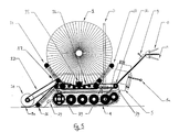
- FIGs 5 to 8 illustrate a second embodiment of the invention (in which like reference numerals to those used in Figures 1 to 4 indicate like parts), which utilises the cut turf arranged in a roll and wrapped around a spindle or bobbin as in the above described embodiment but in which the spindle or bobbin is not involved in driving the roll, but merely in loading of the roll onto the machine (as described above).
- the roll 2 lies on top of a main roll conveyor 32 between a front roll conveyor 33 and a rear roll conveyor 34.
- the main conveyor 32 is driven by a pinion, driven in turn by a power take-off shaft 36 from the turf roll drive assembly 15.
- the roll 2 is driven from the centre thereof and hence, in order to synchronise the speed of issue of turf with the speed of travel of the machine, the speed of driving the roll must be altered as the diameter of the roll decreases
- the roll is driven from its periphery by means of the above-mentioned conveyors 32 to 34. Because the periphery is driven, the speed of travel of the machine need only be synchronised to the speed of the conveyors. This is effected by means of gearbox 39.
- Numeral 35 indicates a pinion which holds the main conveyor 32 in place.
- Laying is effected by means of the conveyors and after laying, the turf is rolled by output roller 24 ( Figure 5) which is, in this case, driven in clockwise rotation by belt 22 supported by a pivotally mounted frame.
- the belt 22 is driven by rotation of the main conveyor 32.
- the turf 1a that is to be laid passes over a turf guide conveyor 38 which may have a convex cross section (as shown in Figure 10) to ensure accurate abutment of adjacent turf strips as described above with reference to output chute 18, and which is driven by rotation of the main conveyor 32.
- Lift cradle 31 is lowered by means of lift frame 37 (which parts are similar in function to handle 26 and cranks 25 of the first embodiment) to enable the turf 1a from the roll 1 to be pressed onto the ground by the roller 24 as that turf 1a is laid.
- Cog wheels and chains 40 ( Figures 7 and 8) extend between the previously mentioned power take-off shaft 36 and the also previously mentioned front roll conveyor 33 to transmit drive to the latter.
- Operation of the gear lever or selector 5a, the throttle 9, and the clutch controls 10 enable the machine to be driven in a forward direction (as discussed above), the roll 1 being rotated at a synchronised speed by the main conveyor 32, the front roll conveyor 33 and the rear roll conveyor 34. Since these conveyors constantly contact the exterior surface of the roll 1, the speed of issue of the turf 1a being laid from the roll 1 will match the substantially constant speed of "laying" travel of the machine as the roll 1 being dispensed progressively reduces in diameter, provided that the speed of the conveyors is synchronised with the speed of the tracks.
- the speed of non-laying transit travel might typically be about 6 kilometres per hour whereas the operative or laying speed might be between about 0.6 and 1.37 kilometres per hour.
- the roll 1 is cut to match the required location of that end.
- a third embodiment of the invention illustrated in Figure 9 utilises the peripheral drive of the second embodiment, but includes a system for loading the roll onto the machine.
- the output conveyor 38 is replaced by an output guide chute 28, which chute may be convex in cross section as described with reference to the first and second embodiments (see Fig. 10).
- the roll is pulled up the chute 28 by means of a winch system, the operation of which is described below.
- winch-cradle arms 41 are unclipped from pivot bearings 42 located on winch-frame 43 enabling them to be pulled out from the machine and attached by means of a latch 44 to spigots at either end of the spindle 2.
- the roll 1 is then pulled on to the machine by selecting a suitable gear in the winch and conveyor gearbox 45 by means of the winch/conveyor gear lever 46.
- the winch and conveyor gearbox 45 is located between the power take-off shaft 36 and main roll conveyor 32 and has three operating positions.
- Side guide plates and rear slide plate 49 further act to maintain the position of the roll on the machine and allow the turf to slide off the machine as required.
- a rotating cultivator 50 driven via drive chains 51 is provided to repair marks or depressions in the prepared soil upon which the turf 1 is to be laid.
- the rear guide chute 28 is lifted off the ground by means of the lever 52 and cable 56.
- the machine is aligned in a forward direction relative to the intended line along which that turf is to lie, the winch and conveyor gearbox is set to the "conveyor" position and the engine is put in forward gear.
- the engine now drives the tracks 4 and the roll conveyor 32 thereby rotating the roll 1 as the machine moves forwards as with the above described second embodiment.
- This is controlled by means of a track brake and steering control levers 11 as well as a throttle.
- the tension of the roll conveyor 32 is maintained by means of roll conveyor sliders 54 which are held by springs. These sliders allow the roll conveyor 32 to sag by a predetermined amount and to take on substantially the shape of the bottom of the roll 1 when it is loaded. This ensures that a maximum area of conveyor 32 is in contact with the roll 1, thereby providing maximum traction to drive the turf off the machine.
- the machine which have been described preferably have a width of substantially 1.2 metres, a length of substantially 2.2 metres and, when loaded, a height of substantially 1.2 metres. Such a width allows the machine to be driven through a garden gate or the like, which is desirable if the area to be turfed is only accessible through for example a narrow passage or garage doorway.
- a turf roll has a weight of substantially 500 kilograms and the machine itself has a weight of substantially 250 kilograms so that, when loaded at the beginning of an operation, the machine will have a weight of substantially 750 kilograms.
- Its ground loading, or pressure upon the ground is approximately 197 grams per square centimetre and it is noted that this is more or less equivalent to the walking ground loading of an average man.
- the machine illustrated in the drawings and have been described will be fitted with safety guards and shields but that these are completely omitted from said drawings for the sake of clarity.
Landscapes
- Life Sciences & Earth Sciences (AREA)
- Environmental Sciences (AREA)
- Transplanting Machines (AREA)
- Cultivation Of Plants (AREA)
Claims (17)
- Appareil de pose de gazon, l'appareil comportant:
un châssis (3);
des moyens de support et de transport (32 à 34, 19, 2, 41) montés sur le châssis pour porter un rouleau de gazon;
des moyens de propulsion (5, 6) auxquels ledit châssis est relié pour entraîner le châssis vers l'avant sur la surface d'un sol à une vitesse d'entraînement suivant laquelle le gazon est à poser;
des moyens de synchronisation (15, 39) pour synchroniser les moyens de transport et les moyens de propulsion pour permettre de synchroniser la pose du gazon essentiellement avec la vitesse d'entraînement; caractérisé en ce que:
les moyens de support et de transport (32 à 34, 19) sont agencés de manière à se trouver au contact, en utilisation, avec une partie importante de la surface circonférentielle du rouleau de gazon, au niveau du côté inférieur de ce dernier, afin de faire tourner le rouleau de manière à provoquer le déroulement de celui-ci, et à transporter le gazon vers la surface du sol derrière les moyens de propulsion, partie importante qui s'étend à partir des deux côtés d'un plan imaginaire qui est sensiblement perpendiculaire au châssis et qui inclut l'axe du rouleau de gazon. - Appareil selon la revendication 1, dans lequel les moyens de support de gazon comportent un arbre (2) autour duquel est enroulé ledit rouleau de gazon.
- Appareil selon la revendication 1 ou la revendication 2, dans lequel lesdits moyens de transport de gazon comportent au moins un convoyeur (32) positionné de façon à porter contre la partie constituée par la surface circonférentielle dudit rouleau.
- Appareil selon l'une quelconque des revendications précédentes, caractérisé en outre par la présence de moyens de guidage de gazon (28, 38) pour guider ledit gazon depuis lesdits moyens de transport jusqu'à ladite surface du sol derrière lesdits moyens de propulsion.
- Appareil selon la revendication 4, dans lequel les moyens de guidage sont constitués par une goulotte (28, 38) dont la largeur est au moins égale à celle dudit rouleau de gazon, les moyens de guidage présentant un profil sensiblement convexe dans le sens de la largeur de la goulotte.
- Appareil selon la revendication 5, dans lequel la goulotte est montée à pivotement sur ledit châssis.
- Appareil selon l'une quelconque des revendications précédentes, dans lequel les moyens de propulsion comportent au moins deux chenilles d'entraînement sans fin.
- Appareil selon la revendication 7, dans lequel les moyens de propulsion comportent en outre un moteur à combustion interne et des engrenages d'entraînement (39) disposés entre ledit moteur et lesdites chenilles d'entraînement permettant d'obtenir au moins une vitesse de marche arrière et au moins une vitesse de marche avant pour permettre d'entraîner lesdites chenilles (6) à au moins une vitesse en marche arrière, de transit, et à au moins une vitesse en marche avant, de pose.
- Appareil selon la revendication 7 ou la revendication 8, dans laquelle les chenilles d'entraînement sont positionnées de manière à se situer à l'intérieur de la largeur du rouleau de gazon.
- Appareil selon l'une quelconque des revendications précédentes, dans lequel les moyens de synchronisation (39) comportent des moyens de réglage pouvant être actionnés par l'utilisateur pour permettre à un utilisateur de l'appareil de régler ladite vitesse de transport dudit gazon en fonction de ladite vitesse d'entraînement.
- Appareil selon l'une quelconque des revendications précédentes, dans lequel les moyens de synchronisation comportent des moyens de réglage automatique pour régler automatiquement ladite vitesse de transport dudit gazon en fonction de ladite vitesse d'entraînement.
- Appareil selon la revendication 11, dans lequel les moyens de réglage automatique sont agencés de manière à modifier de façon continue la vitesse de transport du gazon.
- Appareil selon l'une quelconque des revendications précédentes, caractérisé en outre en ce qu'un rouleau (24) est relié à l'arrière du châssis pour rouler ledit gazon posé.
- Appareil selon l'une quelconque des revendications précédentes, caractérisé en outre en ce que des moyens de réparation (29, 50) sont reliés à l'arrière du châssis pour réparer ladite surface du sol immédiatement avant la pose dudit gazon.
- Appareil selon la revendication 14, dans lequel les moyens de réparation sont constitués par un râteau oscillant (29).
- Appareil selon la revendication 14, dans lequel les moyens de réparation sont constitués par un cultivateur rotatif (50).
- Procédé de pose de gazon, le procédé comportant les étapes consistant:
à supporter un rouleau de gazon sur un appareil de pose de gazon comprenant un châssis;
à entraîner ledit châssis, à l'aide de moyens de propulsion auxquels ledit châssis est relié, vers l'avant sur la surface d'un sol à une vitesse d'entraînement à laquelle ledit gazon est à poser;
à transporter ledit gazon vers ladite surface du sol derrière lesdits moyens de propulsion; et
à synchroniser ladite pose dudit gazon avec ladite vitesse d'entraînement de sorte que ledit gazon soit posé sensiblement à ladite vitesse d'entraînement; caractérisé par le fait de:
venir au contact d'une partie importante de la surface circonférentielle dudit rouleau de gazon, au niveau du côté inférieur de ce dernier, afin de faire tourner le rouleau de manière à provoquer le déroulement de celui-ci, partie importante qui s'étend à partir des deux côtés d'un plan imaginaire qui est sensiblement perpendiculaire à la surface du sol et qui inclut l'axe du rouleau de gazon.
Priority Applications (1)
| Application Number | Priority Date | Filing Date | Title |
|---|---|---|---|
| AT90310678T ATE101473T1 (de) | 1989-09-29 | 1990-09-28 | Vorrichtung zur verarbeitung von grassoden. |
Applications Claiming Priority (8)
| Application Number | Priority Date | Filing Date | Title |
|---|---|---|---|
| GB898922014A GB8922014D0 (en) | 1989-09-29 | 1989-09-29 | Turf laying machine |
| GB8922014 | 1989-09-29 | ||
| GB8922808 | 1989-10-10 | ||
| GB898922808A GB8922808D0 (en) | 1989-10-10 | 1989-10-10 | Turf cutting machine |
| GB9003377 | 1990-02-14 | ||
| GB909003377A GB9003377D0 (en) | 1990-02-14 | 1990-02-14 | Turf laying machine |
| GB9016195 | 1990-07-24 | ||
| GB909016195A GB9016195D0 (en) | 1990-07-24 | 1990-07-24 | Turf laying machine |
Publications (3)
| Publication Number | Publication Date |
|---|---|
| EP0420689A2 EP0420689A2 (fr) | 1991-04-03 |
| EP0420689A3 EP0420689A3 (en) | 1991-09-04 |
| EP0420689B1 true EP0420689B1 (fr) | 1994-02-16 |
Family
ID=27450412
Family Applications (1)
| Application Number | Title | Priority Date | Filing Date |
|---|---|---|---|
| EP90310678A Expired - Lifetime EP0420689B1 (fr) | 1989-09-29 | 1990-09-28 | Dispositif pour la manutension de gazon |
Country Status (5)
| Country | Link |
|---|---|
| US (1) | US5129462A (fr) |
| EP (1) | EP0420689B1 (fr) |
| AU (1) | AU6366490A (fr) |
| CA (1) | CA2026473C (fr) |
| DE (1) | DE69006671T2 (fr) |
Cited By (1)
| Publication number | Priority date | Publication date | Assignee | Title |
|---|---|---|---|---|
| WO2008064166A3 (fr) * | 2006-11-17 | 2008-07-10 | G2 Turftools Inc | Dispositif de pose de gazon en rouleaux |
Families Citing this family (39)
| Publication number | Priority date | Publication date | Assignee | Title |
|---|---|---|---|---|
| US5215278A (en) * | 1991-12-02 | 1993-06-01 | Hess Douglas S | Apparatus for laying turf |
| AU673365B2 (en) * | 1992-07-03 | 1996-11-07 | Huber Ranch Sod Nursery Inc. | Vibro netter |
| GB2284225B (en) * | 1992-07-03 | 1996-04-03 | Strathayr Instant Lawn Pty Ltd | Vibro netter |
| FR2695534B1 (fr) * | 1992-09-11 | 1994-12-30 | Sodiape | Machine à déposer le gazon. |
| GB9224431D0 (en) * | 1992-11-21 | 1993-01-13 | Rolawn Limited | Turf laying apparatus |
| US5307880A (en) * | 1993-03-12 | 1994-05-03 | Woerner Edward E | Sod roll-out machine with endless tracks |
| AUPM922894A0 (en) * | 1994-11-04 | 1994-11-24 | Strathayr Pty. Limited | Methods of and apparatus for laying turf |
| JPH11501439A (ja) * | 1995-03-02 | 1999-02-02 | ミネソタ・マイニング・アンド・マニュファクチャリング・カンパニー | 構造化研磨物品を用いて支持体をテクスチャリングする方法 |
| NL1001102C2 (nl) * | 1995-08-31 | 1997-03-03 | Leonardus Lambertus Van Loen | Inrichting voor het uitleggen van een tot een rol gewikkeld produkt. |
| US5697452A (en) * | 1995-12-05 | 1997-12-16 | American Roller Bushing Corporation | Sod roll laying apparatus and method |
| US6056231A (en) * | 1996-05-14 | 2000-05-02 | Owens Corning Fiberglas Technology, Inc. | Pushing member for apparatus for paying out a roll of insulation material |
| US5775436A (en) * | 1996-07-26 | 1998-07-07 | Steiner Turf Equipment, Inc. | Sod harvester with pivotable roll-forming unit |
| US5988289A (en) * | 1997-08-04 | 1999-11-23 | Holland; Gregory Paul | Sod laying apparatus |
| US6131668A (en) * | 1997-12-29 | 2000-10-17 | Clark Equipment Company | Sod laying apparatus and method |
| US6213218B1 (en) | 1998-10-22 | 2001-04-10 | Donald R. Miller | Sod laying apparatus |
| US6419424B1 (en) * | 1998-11-11 | 2002-07-16 | Null's Machine & Mfg., Inc. | Coil pipe trailer |
| US6550406B2 (en) | 2001-03-21 | 2003-04-22 | Anthony C. Bass | Sod roll installation device |
| US7673697B2 (en) | 2002-01-23 | 2010-03-09 | Jonathan Michael Peterson | Sod laying machine |
| WO2004004444A1 (fr) * | 2002-07-04 | 2004-01-15 | Ricardo Rodriguez De La Cruz | Equipement agricole destine a retenir l'humidite |
| CA2520167A1 (fr) * | 2004-09-23 | 2006-03-23 | 1045929 Ontario Limited | Poseuse de gazon en plaques |
| DE102008006855A1 (de) | 2008-01-31 | 2008-08-07 | Clariant International Limited | Phosphorsäureester enthaltend über Diol-Einheiten verbrückte Phosphoratome |
| DE102008006858A1 (de) | 2008-01-31 | 2008-08-14 | Clariant International Ltd. | Wässrige Zusammensetzungen enthaltend alkoxylierte Phosphorsäuretriester |
| US20090107775A1 (en) * | 2007-10-25 | 2009-04-30 | Automated Ag Systems, Llc | Sod Harvester |
| US8540180B2 (en) * | 2009-03-06 | 2013-09-24 | Marc F. SOBAS | Apparatus and method for distribution of a floor covering |
| EP2255607A1 (fr) * | 2009-05-29 | 2010-12-01 | Uniek Graszodenkwekerij | Dispositif de pose de matériau en toile sur une surface ou de retrait d'une surface |
| US20100303596A1 (en) * | 2009-05-29 | 2010-12-02 | Automated Ag Systems, Llc | Bin Carrier System |
| US8714902B2 (en) * | 2010-02-12 | 2014-05-06 | Jones Practical Innovations, Llc | System and method for unwrapping round modules |
| US8974311B2 (en) * | 2010-08-10 | 2015-03-10 | Technology Licensing Corp. | Method and device for installing synthetic turf |
| US8403345B2 (en) * | 2011-05-13 | 2013-03-26 | Michael Angelo Designs, Llc | Apparatus with wire cart for moving, storing and dispensing spooled material |
| DE202013101350U1 (de) * | 2013-03-27 | 2014-07-03 | Smg Sportplatzmaschinenbau Gmbh | Vorrichtung zum Auf- oder Abwickeln von flächigem Bahnenmaterial |
| US9451739B2 (en) * | 2013-05-16 | 2016-09-27 | Dustin Miller | Agricultural undercut implements and methods |
| US9868605B2 (en) | 2014-02-12 | 2018-01-16 | Andrew L. Bishop | Geotextile rolling apparatus |
| US8794342B1 (en) * | 2014-04-01 | 2014-08-05 | O2 Turftools, Inc. | Turf seamer |
| AU2017257882B2 (en) | 2016-04-29 | 2019-10-03 | Motz Enterprises, Inc. | System and method for rolling up a flexible sheet |
| EP3999294A4 (fr) | 2019-07-17 | 2024-07-17 | John M. Scales | Matelas de lutte contre l'érosion articulable, système de fabrication, système de roulement de matelas et procédés |
| GB2589292A (en) * | 2019-09-13 | 2021-06-02 | Faun Trackway Ltd | Traversable road covering track |
| CN110817612A (zh) * | 2019-12-05 | 2020-02-21 | 浙江正泰电缆有限公司 | 一种电缆收放集装箱及装有该集装箱的运输车 |
| IT202200007547A1 (it) * | 2022-04-14 | 2023-10-14 | Learco Galardini | Macchina per distendere tappeti erbosi |
| US12084102B1 (en) | 2023-03-03 | 2024-09-10 | Jason O'Neal | Methods and systems for moving a roll of turf end first |
Family Cites Families (22)
| Publication number | Priority date | Publication date | Assignee | Title |
|---|---|---|---|---|
| US2977058A (en) * | 1957-12-18 | 1961-03-28 | Jagenberg Werk A G | Apparatus for unwinding a supply roll in paper processing machines |
| US3235011A (en) * | 1962-12-12 | 1966-02-15 | Richard A Pasinski | Sod roll forming machine |
| US3982711A (en) * | 1975-04-09 | 1976-09-28 | Bradley Frank M | Sod laying machine |
| US4084763A (en) * | 1976-04-05 | 1978-04-18 | Frank J. Zamboni & Co. | Machine for handling artificial turf or the like |
| US4149640A (en) * | 1976-06-07 | 1979-04-17 | White John M | Means for laying sod |
| US4088069A (en) * | 1976-06-08 | 1978-05-09 | Deere & Company | Elastic bale-forming conveyor for cylindrical bales |
| FR2371868A1 (fr) * | 1976-11-30 | 1978-06-23 | Rabaud Claude | Machine d'enlevement, de transport et de debitage de balles de paille ou foin roulees |
| US4095706A (en) * | 1977-04-11 | 1978-06-20 | Nichols, Farrow, Schwien And Schwien | Vertically swinging big bale handling and grasping apparatus |
| US4195958A (en) * | 1978-05-30 | 1980-04-01 | Wayne Diekemper | Bale unroller |
| US4221268A (en) * | 1978-12-21 | 1980-09-09 | Caterpillar Tractor Co. | Slide rail assembly for a work vehicle |
| IT1124975B (it) * | 1979-11-13 | 1986-05-14 | Becometa Snc | Apparecchiatura per lo srotolamento di balle cilindriche di fieno,paglia e simili e per la distribuzione dosata dei medesimi prodotti direttamente nel luogo di utilizzo |
| SU990100A2 (ru) * | 1981-09-24 | 1983-01-23 | Ставропольский научно-исследовательский институт сельского хозяйства | Устройство дл нарезки и укладки дерна |
| US4428707A (en) * | 1981-11-20 | 1984-01-31 | Cockle Richard A | Round bale feeder |
| CA1217785A (fr) * | 1984-02-20 | 1987-02-10 | Brouwer Turf Equipment Limited | Mecanisme de pivotement pour machine de prelevement de gazon en plaques |
| CA1243550A (fr) * | 1984-09-17 | 1988-10-25 | Brouwer Turf Equipment Limited | Machine et methode de pose de gazon en plaques |
| FR2574244A1 (fr) * | 1984-12-10 | 1986-06-13 | Moreau Ets Jean | Machine de manutention de balles de paille |
| SE8500694L (sv) * | 1985-02-14 | 1986-08-15 | Ihab | Anordning for utleggning av markteckningsmaterial |
| CA1260021A (fr) * | 1985-10-28 | 1989-09-26 | Brouwer Turf Equipment Limited | Dispositif et methode de recolte des plaques de gazon |
| GB2189123B (en) * | 1986-04-19 | 1989-11-29 | Fred Powell Manufacturing | Straw laying apparatus |
| FR2597701B1 (fr) * | 1986-04-25 | 1989-03-24 | Gabard Raymond | Machine pour derouler, assembler et plaquer sur le sol des rouleaux de gazon precultive. |
| US4762291A (en) * | 1987-06-11 | 1988-08-09 | Sauber Charles J | Self-loading reel trailer |
| CA1288277C (fr) * | 1988-01-12 | 1991-09-03 | Leroy Knudson | Dispositif de compression des balles |
-
1990
- 1990-09-28 CA CA002026473A patent/CA2026473C/fr not_active Expired - Lifetime
- 1990-09-28 AU AU63664/90A patent/AU6366490A/en not_active Abandoned
- 1990-09-28 EP EP90310678A patent/EP0420689B1/fr not_active Expired - Lifetime
- 1990-09-28 DE DE69006671T patent/DE69006671T2/de not_active Expired - Fee Related
- 1990-10-01 US US07/591,080 patent/US5129462A/en not_active Expired - Lifetime
Cited By (1)
| Publication number | Priority date | Publication date | Assignee | Title |
|---|---|---|---|---|
| WO2008064166A3 (fr) * | 2006-11-17 | 2008-07-10 | G2 Turftools Inc | Dispositif de pose de gazon en rouleaux |
Also Published As
| Publication number | Publication date |
|---|---|
| EP0420689A2 (fr) | 1991-04-03 |
| AU6366490A (en) | 1991-04-11 |
| EP0420689A3 (en) | 1991-09-04 |
| DE69006671D1 (de) | 1994-03-24 |
| CA2026473C (fr) | 2002-01-15 |
| DE69006671T2 (de) | 1994-09-22 |
| CA2026473A1 (fr) | 1991-03-30 |
| US5129462A (en) | 1992-07-14 |
Similar Documents
| Publication | Publication Date | Title |
|---|---|---|
| EP0420689B1 (fr) | Dispositif pour la manutension de gazon | |
| EP0178081B1 (fr) | Machine à poser des mottes de gazon et méthode | |
| US4084763A (en) | Machine for handling artificial turf or the like | |
| EP0573620B1 (fr) | Appareil servant a poser du gazon | |
| US4343132A (en) | Bale wrapping device and method | |
| US4789289A (en) | Bale loader, handler and feeder | |
| US4564150A (en) | Apparatus for continuously supplying a web of sheet material | |
| US6364027B1 (en) | Sod harvester | |
| US4044967A (en) | Round bale feeder | |
| US4968205A (en) | Round haybale unloader | |
| US3587218A (en) | Roll forming fodder harvesters | |
| US4149640A (en) | Means for laying sod | |
| US10631461B1 (en) | Device and system for extracting and densifying agricultural plastics | |
| US4673142A (en) | Apparatus for continuously supplying a web of sheet material | |
| US4614313A (en) | Apparatus for continuously supplying a web of sheet material | |
| US4307522A (en) | Land Grading Machine | |
| GB2213796A (en) | Strip laying apparatus | |
| US4717087A (en) | Apparatus for continuously supplying a web of sheet material | |
| RU2849381C1 (ru) | Самоходный оборачиватель лент льна | |
| CN116395444B (zh) | 一种全自动滴灌带回收装置 | |
| EP4461125A1 (fr) | Enveloppeur de balles | |
| JP3451268B2 (ja) | 苗巻取方法及び苗巻取補助装置 | |
| US3648779A (en) | Sod roll forming machine | |
| CN119866691A (zh) | 一种用于盐碱地牧草种植的起垄覆膜设备 | |
| WO2024161352A1 (fr) | Dispositif et procédé de traitement de plantes |
Legal Events
| Date | Code | Title | Description |
|---|---|---|---|
| PUAI | Public reference made under article 153(3) epc to a published international application that has entered the european phase |
Free format text: ORIGINAL CODE: 0009012 |
|
| AK | Designated contracting states |
Kind code of ref document: A2 Designated state(s): AT BE CH DE DK ES FR GB GR IT LI LU NL SE |
|
| DIN1 | Information on inventor provided before grant (deleted) | ||
| RAP1 | Party data changed (applicant data changed or rights of an application transferred) |
Owner name: LAWN TECHNOLOGY LIMITED |
|
| RIN1 | Information on inventor provided before grant (corrected) |
Inventor name: MAIL, STUART PAUL |
|
| PUAL | Search report despatched |
Free format text: ORIGINAL CODE: 0009013 |
|
| AK | Designated contracting states |
Kind code of ref document: A3 Designated state(s): AT BE CH DE DK ES FR GB GR IT LI LU NL SE |
|
| 17P | Request for examination filed |
Effective date: 19910928 |
|
| 17Q | First examination report despatched |
Effective date: 19911223 |
|
| GRAA | (expected) grant |
Free format text: ORIGINAL CODE: 0009210 |
|
| RAP1 | Party data changed (applicant data changed or rights of an application transferred) |
Owner name: TURFGRASS SERVICES INTERNATIONAL LTD |
|
| AK | Designated contracting states |
Kind code of ref document: B1 Designated state(s): AT BE CH DE DK ES FR GB GR IT LI LU NL SE |
|
| PG25 | Lapsed in a contracting state [announced via postgrant information from national office to epo] |
Ref country code: IT Free format text: LAPSE BECAUSE OF FAILURE TO SUBMIT A TRANSLATION OF THE DESCRIPTION OR TO PAY THE FEE WITHIN THE PRESCRIBED TIME-LIMIT;WARNING: LAPSES OF ITALIAN PATENTS WITH EFFECTIVE DATE BEFORE 2007 MAY HAVE OCCURRED AT ANY TIME BEFORE 2007. THE CORRECT EFFECTIVE DATE MAY BE DIFFERENT FROM THE ONE RECORDED. Effective date: 19940216 Ref country code: AT Effective date: 19940216 Ref country code: CH Effective date: 19940216 Ref country code: ES Free format text: THE PATENT HAS BEEN ANNULLED BY A DECISION OF A NATIONAL AUTHORITY Effective date: 19940216 Ref country code: DK Effective date: 19940216 Ref country code: SE Effective date: 19940216 Ref country code: LI Effective date: 19940216 Ref country code: GR Free format text: LAPSE BECAUSE OF FAILURE TO SUBMIT A TRANSLATION OF THE DESCRIPTION OR TO PAY THE FEE WITHIN THE PRESCRIBED TIME-LIMIT Effective date: 19940216 |
|
| REF | Corresponds to: |
Ref document number: 101473 Country of ref document: AT Date of ref document: 19940315 Kind code of ref document: T |
|
| REF | Corresponds to: |
Ref document number: 69006671 Country of ref document: DE Date of ref document: 19940324 |
|
| REG | Reference to a national code |
Ref country code: CH Ref legal event code: PL |
|
| ET | Fr: translation filed | ||
| PG25 | Lapsed in a contracting state [announced via postgrant information from national office to epo] |
Ref country code: LU Free format text: LAPSE BECAUSE OF NON-PAYMENT OF DUE FEES Effective date: 19940930 |
|
| PLBI | Opposition filed |
Free format text: ORIGINAL CODE: 0009260 |
|
| 26 | Opposition filed |
Opponent name: VAN VUUREN, JOHANNES Effective date: 19941116 |
|
| NLR1 | Nl: opposition has been filed with the epo |
Opponent name: VAN VUUREN , JOHANNES |
|
| PLBL | Opposition procedure terminated |
Free format text: ORIGINAL CODE: EPIDOS OPPC |
|
| PLBM | Termination of opposition procedure: date of legal effect published |
Free format text: ORIGINAL CODE: 0009276 |
|
| STAA | Information on the status of an ep patent application or granted ep patent |
Free format text: STATUS: OPPOSITION PROCEDURE CLOSED |
|
| 27C | Opposition proceedings terminated |
Effective date: 19970118 |
|
| NLR2 | Nl: decision of opposition | ||
| PGFP | Annual fee paid to national office [announced via postgrant information from national office to epo] |
Ref country code: FR Payment date: 19970925 Year of fee payment: 8 |
|
| PGFP | Annual fee paid to national office [announced via postgrant information from national office to epo] |
Ref country code: NL Payment date: 19970929 Year of fee payment: 8 |
|
| PGFP | Annual fee paid to national office [announced via postgrant information from national office to epo] |
Ref country code: DE Payment date: 19971010 Year of fee payment: 8 |
|
| PGFP | Annual fee paid to national office [announced via postgrant information from national office to epo] |
Ref country code: BE Payment date: 19971118 Year of fee payment: 8 |
|
| REG | Reference to a national code |
Ref country code: GB Ref legal event code: 732E |
|
| PG25 | Lapsed in a contracting state [announced via postgrant information from national office to epo] |
Ref country code: BE Free format text: LAPSE BECAUSE OF NON-PAYMENT OF DUE FEES Effective date: 19980930 |
|
| BERE | Be: lapsed |
Owner name: TURFGRASS SERVICES INTERNATIONAL LTD Effective date: 19980930 |
|
| PG25 | Lapsed in a contracting state [announced via postgrant information from national office to epo] |
Ref country code: NL Free format text: LAPSE BECAUSE OF NON-PAYMENT OF DUE FEES Effective date: 19990401 |
|
| PG25 | Lapsed in a contracting state [announced via postgrant information from national office to epo] |
Ref country code: FR Free format text: LAPSE BECAUSE OF NON-PAYMENT OF DUE FEES Effective date: 19990531 |
|
| NLV4 | Nl: lapsed or anulled due to non-payment of the annual fee |
Effective date: 19990401 |
|
| PG25 | Lapsed in a contracting state [announced via postgrant information from national office to epo] |
Ref country code: DE Free format text: LAPSE BECAUSE OF NON-PAYMENT OF DUE FEES Effective date: 19990701 |
|
| REG | Reference to a national code |
Ref country code: FR Ref legal event code: ST |
|
| REG | Reference to a national code |
Ref country code: GB Ref legal event code: IF02 |
|
| PLAB | Opposition data, opponent's data or that of the opponent's representative modified |
Free format text: ORIGINAL CODE: 0009299OPPO |
|
| PGFP | Annual fee paid to national office [announced via postgrant information from national office to epo] |
Ref country code: GB Payment date: 20090923 Year of fee payment: 20 |
|
| REG | Reference to a national code |
Ref country code: GB Ref legal event code: PE20 Expiry date: 20100927 |
|
| PG25 | Lapsed in a contracting state [announced via postgrant information from national office to epo] |
Ref country code: GB Free format text: LAPSE BECAUSE OF EXPIRATION OF PROTECTION Effective date: 20100927 |