EP0420715A1 - Dispositif pour la prise de vues de corps masqués en totalité ou en partie, utilisable notamment dans le domaine dentaire - Google Patents
Dispositif pour la prise de vues de corps masqués en totalité ou en partie, utilisable notamment dans le domaine dentaire Download PDFInfo
- Publication number
- EP0420715A1 EP0420715A1 EP90402523A EP90402523A EP0420715A1 EP 0420715 A1 EP0420715 A1 EP 0420715A1 EP 90402523 A EP90402523 A EP 90402523A EP 90402523 A EP90402523 A EP 90402523A EP 0420715 A1 EP0420715 A1 EP 0420715A1
- Authority
- EP
- European Patent Office
- Prior art keywords
- mirror
- handle
- aforesaid
- camera
- articulation
- Prior art date
- Legal status (The legal status is an assumption and is not a legal conclusion. Google has not performed a legal analysis and makes no representation as to the accuracy of the status listed.)
- Withdrawn
Links
- 210000000214 mouth Anatomy 0.000 claims abstract description 8
- 230000005540 biological transmission Effects 0.000 abstract 1
- 238000012937 correction Methods 0.000 description 2
- 210000000887 face Anatomy 0.000 description 2
- 239000013307 optical fiber Substances 0.000 description 2
- 238000004140 cleaning Methods 0.000 description 1
- 238000006073 displacement reaction Methods 0.000 description 1
- 230000004907 flux Effects 0.000 description 1
- 230000003993 interaction Effects 0.000 description 1
- 239000000463 material Substances 0.000 description 1
- 230000001954 sterilising effect Effects 0.000 description 1
- 238000004659 sterilization and disinfection Methods 0.000 description 1
Images
Classifications
-
- A—HUMAN NECESSITIES
- A61—MEDICAL OR VETERINARY SCIENCE; HYGIENE
- A61B—DIAGNOSIS; SURGERY; IDENTIFICATION
- A61B1/00—Instruments for performing medical examinations of the interior of cavities or tubes of the body by visual or photographical inspection, e.g. endoscopes; Illuminating arrangements therefor
- A61B1/24—Instruments for performing medical examinations of the interior of cavities or tubes of the body by visual or photographical inspection, e.g. endoscopes; Illuminating arrangements therefor for the mouth, i.e. stomatoscopes, e.g. with tongue depressors; Instruments for opening or keeping open the mouth
- A61B1/247—Instruments for performing medical examinations of the interior of cavities or tubes of the body by visual or photographical inspection, e.g. endoscopes; Illuminating arrangements therefor for the mouth, i.e. stomatoscopes, e.g. with tongue depressors; Instruments for opening or keeping open the mouth with means for viewing areas outside the direct line of sight, e.g. dentists' mirrors
-
- A—HUMAN NECESSITIES
- A61—MEDICAL OR VETERINARY SCIENCE; HYGIENE
- A61B—DIAGNOSIS; SURGERY; IDENTIFICATION
- A61B1/00—Instruments for performing medical examinations of the interior of cavities or tubes of the body by visual or photographical inspection, e.g. endoscopes; Illuminating arrangements therefor
- A61B1/04—Instruments for performing medical examinations of the interior of cavities or tubes of the body by visual or photographical inspection, e.g. endoscopes; Illuminating arrangements therefor combined with photographic or television appliances
- A61B1/042—Instruments for performing medical examinations of the interior of cavities or tubes of the body by visual or photographical inspection, e.g. endoscopes; Illuminating arrangements therefor combined with photographic or television appliances characterised by a proximal camera, e.g. a CCD camera
-
- A—HUMAN NECESSITIES
- A61—MEDICAL OR VETERINARY SCIENCE; HYGIENE
- A61B—DIAGNOSIS; SURGERY; IDENTIFICATION
- A61B1/00—Instruments for performing medical examinations of the interior of cavities or tubes of the body by visual or photographical inspection, e.g. endoscopes; Illuminating arrangements therefor
- A61B1/06—Instruments for performing medical examinations of the interior of cavities or tubes of the body by visual or photographical inspection, e.g. endoscopes; Illuminating arrangements therefor with illuminating arrangements
- A61B1/0661—Endoscope light sources
- A61B1/0669—Endoscope light sources at proximal end of an endoscope
Definitions
- the present invention relates to devices intended for taking pictures or for transmitting images of concealed bodies, in whole or in part, for direct vision of the human eye or of the lens of a camera. These devices can in particular be used for photographing or filming bodies located in places which are difficult to access and, more particularly in the dental field, for obtaining images of the interior of the oral cavity.
- a dental exploration device which consists of an endoscopic camera mounted on an articulated arm connected to a video monitor.
- a device is also known using a miniature video camera which is fixed on the handle of a conventional dental mirror and with which is associated a light source constituted by an optical fiber itself mounted on the handle of the mirror. The practitioner thus directs the camera lens onto the reflective portion of the mirror on which the light beam provided by the optical fiber is focused, which in particular enables him to capture images of the posterior parts of the teeth.
- this latter device has some drawbacks linked inter alia to the fact that the conventional dental mirror does not have a structure particularly suitable for such use. Indeed, the lack of relative mobility of the mirror and of the camera lens limits in a significant proportion the possible field of vision and therefore the freedom of taking pictures and does not allow to obtain optimally usable images of some parts of the oral cavity difficult to access. This explains why such a device is necessarily equipped with an additional light source, the practitioner being unable to inspect the oral cavity in natural light or using the only operating light commonly used in dental offices.
- the device which is the subject of the present invention does not have such drawbacks. Indeed, its structure, particularly simple and economical as regards its industrial cost price, facilitates and optimizes the interaction of the elements which compose it or which intervene in its functioning.
- this device which comprises a mirror placed at the end of a handle, a light source focused mainly towards said mirror and a camera mounted on said handle with its line of sight substantially directed towards said end, is remarkable in that said end of the handle comprises a first articulation making it possible to position said mirror in different planes included in an angular range going from 200 to 90 ° relative to the plane containing said handle.
- the exploration capabilities of the camera are greatly improved without the need to use a light source other than that constituted in particular by a surgical light, although the device of the invention can be used with a light source of its own like the devices of the prior art.
- the mirror in a plane forming an angle close to 200 ° with the plane containing the handle, it is possible for the camera lens to directly capture the image of the object inspected without it being necessary to separate the camera from its support constituted by said handle; in this operating mode the mirror being somehow retracted.
- the aiming axis of this camera will preferably be located in a second plane parallel to the plane containing the above handle so that said axis does not intercept the end of the handle. In this way also, the camera not being inclined towards the handle, it will not constitute an important screen for the passage of light coming from an external source.
- the device thus illustrated is more particularly intended to be used as a dental instrument.
- FIG. 1 it includes a mirror 1 placed at the end 2a of a straight handle 2 and a miniature camera 3 of the video type also mounted on the handle 2 near the end 2b of the latter and connected by a cable 4 to a monitor not shown.
- the device operates with an independent light source which will be constituted by a conventional operating light which is not illustrated but which will be located substantially above the camera 3, the light beam produced by this being mainly directed towards the mirror 1.
- the end 2a of the handle 2 comprises a first articulation 5a making it possible to position the mirror 1 in different planes included in an angular range going from 200 to 90 ° relative to the plane I containing the handle 2. It will however be understood that the positioning of the mirror in a plane forming a right angle with that containing the handle is of only limited interest in the field of dental exploration. Also, for this type of application, the useful angular range may be between 200 and 110 ° C.
- the articulation 5a around which the mirror 1 can pivot is located in the center of the latter and the camera 3 is fixed on the handle 2 so that its line of sight is located in a second plane II, parallel to the first plane I containing the handle 2, and passes through the center of said mirror at the joint 5a.
- the camera lens can capture the entire image reflected by the mirror regardless of the position given to the latter in these planes forming a non-zero angle with the second plane II.
- the mirror 1 which has a circular shape, and the end 2a of the handle on which is mounted a stirrup 5 whose two arms 6 and 7 are fixed at the level of the 'median axis of the mirror by means of pins 6a, 7a housed in corresponding orifices open in the thickness of the frame of said mirror.
- This assembly constitutes the articulation 5a mentioned above, the mirror thus being able to be moved around the axis of rotation formed by the association of the two pins 6a and 7a.
- the end 2a of the handle 2 comprises a second articulation 5b at the level of the attachment of the legs of the stirrup 5 to the handle itself.
- This second articulation is constituted by pins 6b, 7b carried respectively by the arms 6 and 7 of the stirrup and which are housed in corresponding orifices open on the lateral faces of the handle 2.
- This articulation 5b makes it possible, as shown in FIG. 2, to bring the mirror 1 out of the plane II containing the line of sight of the camera in order to achieve direct views of the teeth but also in order to spread during taking sessions. of views, the soft parts of the oral cavity, for example the tongue, with the posterior part of said mirror.
- the two articulations 5a and 5b are provided with brake means which act on the branches of the caliper 5.
- These brake means are, in the embodiment described, constituted by bosses 8 located on the one hand on the mirror frame and on the other hand on the side faces of the handle, symmetrically opposite the attachment points of the stirrup branches.
- bosses 8 are shown in FIG. 4 which more particularly represents the connection between the branch 7 of the stirrup and the end 2a of the handle 2. As can be understood, the rotation of the branch 7 around the stud 7b will thus be braked by the presence of the bosses arranged circumferentially around the housing of the stud 7b open on the corresponding lateral face of the handle.
- the legs of the stirrup have a certain flexibility and that the bosses are made so as not to constitute significant projections on the edges of the mirror or on the lateral faces of the handle, so that the displacement of the branches of the stirrup around the articulation 5b or the rotation of the mirror around the articulation 5a can be operated by applying a light force on said branches or tightening said mirror.
- the device of the invention comprises a groove longitudinal 20 open on the handle 2 near the end 2b, and in which the foot 30 of the camera 3 is slidably housed. In this way, by moving the camera along said groove, the practitioner can, without move the stick, get enlarged views or panoramic images.
- the camera is advantageously rotatably mounted around its line of sight.
- the device of the invention offers very great possibilities for use, in particular allowing an infinity of combined adjustments of the mirror and camera.
- the elements such as mirror, handle, camera stand and camera can be separated from each other to be subjected to sterilization or cleaning.
Landscapes
- Health & Medical Sciences (AREA)
- Life Sciences & Earth Sciences (AREA)
- Surgery (AREA)
- Biophysics (AREA)
- Biomedical Technology (AREA)
- Veterinary Medicine (AREA)
- Nuclear Medicine, Radiotherapy & Molecular Imaging (AREA)
- Optics & Photonics (AREA)
- Pathology (AREA)
- Radiology & Medical Imaging (AREA)
- Public Health (AREA)
- Engineering & Computer Science (AREA)
- Physics & Mathematics (AREA)
- Heart & Thoracic Surgery (AREA)
- Medical Informatics (AREA)
- Molecular Biology (AREA)
- Animal Behavior & Ethology (AREA)
- General Health & Medical Sciences (AREA)
- Dentistry (AREA)
- Oral & Maxillofacial Surgery (AREA)
- Endoscopes (AREA)
Abstract
L'invention concerne un dispositif destiné à la prise de vues ou à la transmission d'images de corps masqués en totalité ou en partie, ledit dispositif comprenant un miroir 1 disposé à l'extrémité 2a d'un manche 2, une source de lumière focalisée principalement vers ledit miroir et une caméra 3 montée sur ledit manche avec son axe de visée sensiblement dirigé vers ladite extrémité. Ce dispositif est remarquable en ce que ladite extrémité 2a du manche 2 comporte une articulation 5a permettant de positionner ledit miroir 1 dans différents plans compris dans une plage angulaire allant de 200 à 90° par rapport au plan I contenant ledit manche. Le dispositif de l'invention trouve une application dans le domaine dentaire où il peut être utilisé pour la prise et la transmission d'images de l'intérieur de la cavité buccale.
Description
- La présente invention intéresse les dispositifs destinés à la prise de vues ou à la transmission d'images de corps dissimulés, en totalité ou en partie, à la vision directe de l'oeil humain ou de l'objectif d'une caméra. Ces dispositifs peuvent notamment être utilisés pour photographier ou filmer des corps situés dans des lieux difficilement accessibles et, plus particulièrement dans le domaine dentaire, pour obtenir des images de l'intérieur de la cavité buccale.
- Les progrès récents dans la miniaturisation permettent en effet l'introduction de certains appareils d'enregistrement et de transmission des images directement en bouche. On connaît ainsi un dispositif d'exploration dentaire qui consiste en une caméra endoscopique montée sur un bras articulé relié à un moniteur vidéo. On connaît également un dispositif utilisant une caméra vidéo miniature qui est fixée sur le manche d'un miroir dentaire classique et à laquelle est associée une source de lumière constituée par une fibre optique elle-même montée sur le manche du miroir. Le praticien dirige ainsi l'objectif de la caméra sur la portion réflectrice du miroir sur laquelle est focalisé le faisceau lumineux fourni par la fibre optique, ce qui lui permet notamment de saisir des images des parties postérieures des dents.
- Bien que d'un intérêt certain, ce dernier dispositif présente quelques inconvénients liés entre autre au fait que le miroir dentaire classique ne présente pas une structure particulièrement adaptée à un tel usage. En effet, le manque de mobilité relative du miroir et de l'objectif de la caméra limite dans des proportions importantes le champ possible de vision et donc la liberté de prise de vues et ne permet des d'obtenir des images exploitables de manière optimale de certaines parties de la cavité buccale d'accès difficile. Ceci explique qu'un tel appareil est nécessairement équipé d'une source de lumière additionnelle, le praticien ne pouvant inspecter la cavité buccale à la lumière naturelle ou à l'aide du seul scialytique utilisé couramment dans les cabinets dentaires.
- On notera d'autre part qu'il en est de même avec le premier dispositif évoqué ci-dessus. Celui-ci exige en effet également l'emploi d'une source de lumière propre. Il en résulte bien évidement une aggravation du coût de ces matériels.
- Le dispositif objet de la présente invention ne présente pas de tels inconvénients. En effet, sa structure, particulièrement simple et économique quant à son prix de revient industriel, facilite et optimise l'interaction des éléments qui le composent ou qui interviennent dans son fonctionnement.
- Conformément à l'invention, ce dispositif, qui comprend un miroir disposé à l'extrémité d'un manche, une source de lumière focalisée principalement vers ledit miroir et une caméra montée sur ledit manche avec son axe de visée sensiblement dirigé vers ledite extrémité, est remarquable en ce que ladite extrémité du manche comporte une première articulation permettant de positionner ledit miroir dans différents plans compris dans une plage angulaire allant de 200 à 90° par rapport au plan contenant ledit manche.
- Ainsi, en donnant au miroir une mobilité suffisante on améliore grandement les facultés d'exploration de la caméra sans qu'il soit nécessaire d'utiliser une source de lumière autre que celle constituée notamment par un scialytique, bien que le dispositif de l'invention puisse être employé avec une source de lumière qui lui soit propre comme les dispositifs de l'art antérieur.
- Avec une source de lumière indépendante, il suffit d'orienter le miroir de manière adéquate pour que ce dernier puisse à la fois capter le maximum de flux lumineux extérieur et fournir sans distorsion quelconque le reflet, par exemple, de la face postérieure d'une dent examinée.
- En outre, en positionnant le miroir dans un plan formant un angle voisin de 200° avec le plan contenant le manche, il est possible à l'objectif de la caméra de saisir directement l'image de l'objet inspecté sans qu'il soit nécessaire de désolidariser la caméra de son support constitué par ledit manche; dans ce mode opératoire le miroir étant en quelque sorte escamoté.
- Pour ce faire, l'axe de visée de cette caméra sera de préférence situé dans un second plan parallèle au plan contenant le susdit manche pour que ledit axe n'intercepte pas l'extrémité du manche. De cette manière également, la caméra n'étant pas inclinée vers le manche, elle ne constituera pas un écran important au passage de la lumière provenant d'une source extérieure.
- Les autres caractéristiques et avantages de la présente invention seront exposés dans la suite de ce mémoire qui donne un exemple de réalisation d'un dispositif conçu conformément aux enseignements de ladit invention, cet exemple étant fourni à titre simplement illustratif et ne pouvant en aucun cas être interprété de manière à limiter le champ de la protection.
- La description de cet exemple se réfère à des dessins sur lesquels:
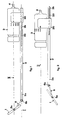
- Les Figures 1 et 2 sont des vues schématiques longitudinales du dispositif en question, montrant deux positions possibles du miroir;
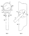
- La Figure 3 est une vue de face de l'extrémité du manche munie de son miroir; et
- La Figure 4 est une vue de détail montrant l'articulation du miroir sur le manche.
- Le dispositf ainsi illustré est plus particulièrement destiné à être utilisé comme instrument dentaire.
- Comme on peut le voir aux Figures 1 et 2, il comprend un miroir 1 disposé à l'extrémité 2a d'un manche droit 2 et une caméra miniature 3 du type vidéo montée également sur le manche 2 au voisinage de l'extrémité 2b de ce dernier et reliée par un cable 4 à un moniteur non représenté.
- Dans le mode de réalisation donné en exemple, le dispositif fonctionne avec une source de lumière indépendante qui sera constituée par un scialytique conventionnel qui n'est pas illustré mais qui sera sensiblement situé au-dessus de la caméra 3, le faisceau lumineux produit par ce scialytique étant principalement dirigé vers le miroir 1.
- Conformément aux enseignements de l'invention, l'extrémité 2a du manche 2 comporte une première articulation 5a permettant de positionner le miroir 1 dans différents plans compris dans une plage angulaire allant de 200 à 90° par rapport au plan I contenant le manche 2. On compendra toutefois que le positionnement du miroir dans un plan formant un angle droit avec celui contenant le manche ne présente qu'un intérêt limité dans le domaine de l'exploration dentaire. Aussi, pour ce type d'application, la plage angulaire utile pourra être comprise entre 200 et 110°C.
- Ainsi qu'on peut l'observer, l'articulation 5a autour de laquelle le miroir 1 peut pivoter, est située au centre de ce dernier et la caméra 3 est fixée sur le manche 2 de telle sorte que son axe de visée soit situé dans un second plan II, parallèle au premier plan I contenant le manche 2, et passe par le centre dudit miroir au niveau de l'articulation 5a.
- De cette manière, l'objectif de la caméra pourra saisir la totalité de l'image reflétée par le miroir quelle que soit la position donnée à ce dernier dans ces plans formant un angle non nul avec le second plan II.
- En se reportant plus particulièrement à la Figure 3, on peut voir le miroir 1, qui possède une forme circulaire, et l'extrémité 2a du manche sur laquelle est monté un étrier 5 dont les deux branches 6 et 7 sont fixées au niveau de l'axe médian du miroir au moyen de tétons 6a, 7a logés dans des orifices correspondants ouverts dans l'épaisseur du cadre dudit miroir. Cet assemblage constitue l'articulation 5a évoquée ci-dessus, le miroir pouvant ainsi être mû autour de l'axe de rotation formé par l'association des deux tétons 6a et 7a.
- Dans le mode de réalisation donné à titre d'exemple, l'extrémité 2a du manche 2 comporte une seconde articulation 5b au niveau de la fixation des branches de l'étrier 5 au manche lui-même.
- Cette seconde articulation est constituée par des tétons 6b, 7b portés respectivement par les branches 6 et 7 de l'étrier et qui sont logés dans des orifices correspondants ouverts sur les faces latérales du manche 2.
- Cette articulation 5b permet, comme le montre la Figure 2, d'amener le miroir 1 hors du plan II contenant l'axe de visée de la caméra afin de réaliser des vues directes des dents mais aussi afin d'écarter lors des séances de prise de vues, les parties molles de la cavité buccale, par exemple la langue, avec la partie postérieure dudit miroir.
- A cet effet, et pour éviter des mouvements de rotation incontrôlés du miroir lors des déplacements du dispositif en bouche, les deux articulations 5a et 5b sont munies de moyens de frein qui agissent sur les branches de l'étrier 5.
- Ces moyens de frein sont, dans le mode de réalisation décrit, constitués par des bossages 8 situés d'une part sur le cadre du miroir et d'autre part sur les faces latérales du manche, de façon symétrique en regard des points de fixation des branches de l'étrier.
- Ces bossages 8 sont montrés à la Figure 4 qui représente plus particulièrement la liaison entre la branche 7 de l'étrier et l'extrémité 2a du manche 2. Ainsi qu'on peut le comprendre, la rotation de la branche 7 autour du téton 7b sera ainsi freinée par la présence des bossages disposés de manière circonférentielle autour du logement du téton 7b ouvert sur la face latérale correspondante du manche.
- Il convient de préciser que les branches de l'étrier présentent une certaine flexibilité et que les bossages sont réalisés de manière à ne pas constituer des saillies importantes sur les bords du miroir ou sur les faces latérales du manche, de telle sorte que le déplacement des branches de l'étrier autour de l'articulation 5b ou la rotation du miroir autour de l'articulation 5a puissent être opérés en appliquant une force légère sur lesdites branches ou ser ledit miroir.
- Afin d'utiliser toutes les possibilités de prises de vues qu'offrent notamment les caméras vidéo ou afin de procéder à des corrections de visée, le dispositif de l'invention, comme on peut l'observer aux Figures 1 et 2, comprend une gorge longitudinale 20 ouverte sur le manche 2 à proximité de l'extrémité 2b, et dans laquelle est logé de manière coulissante le pied 30 de la caméra 3. De cette façon, en déplaçant la caméra le long de ladit gorge, le praticien peut, sans mouvoir le manche, obtenir des grossissements de vues ou des images panoramiques.
- Par ailleurs, afin d'effectuer des corrections de l'horizontalité des images fournies par le miroir, la caméra est avantageusement montée de manière rotative autour de son axe de visée.
- On peut ainsi constater que le dispositif de l'invention offre de très grandes facultés d'utilisation en autorisant notamment une infinité de réglages combinés du miroir et de la caméra.
- Bien évidement, les éléments tels que miroir, manche, pied de caméra et caméra pourront être désolidarisés les uns des autres pour être soumis à stérilisation ou nettoyage.
Claims (9)
1. Dispositif destiné à la prise de vues ou à la transmission d'images de corps masqués en totalité ou en partie, notamment des dents à l'intérieur de la cavité buccale, ledit dispositif comprenant un miroir (1) disposé à l'extrémité (2a) d'un manche (2), une source de lumière focalisée principalement vers ledit miroir et une caméra (3) montée sur ledit manche avec son axe de visée sensiblement dirigé vers ledite extrémité (2a), caractérisé en ce que ladite extrémité (2a) du manche 92) comporte une première articulation (5a) permettant de positionner ledit miroir (1) dans différents plans compris dans une plage angulaire allant de 200 à 90° par rapport au plan (I) contenant ledit manche.
2. Dispositif selon la Revendication 1, caractérisé en ce que le susdit axe de visée est situé dans un second plan (II) parallèle au susdit plan (1) contenant le susdit manche.
3. Dispositif selon les Revendications 1 et 2, caractérisé en ce que le susdit axe de visée passe par le centre du susdit miroir (1) au niveau de la susdite articulation (5a).
4. Dispositif selon l'une quelconque des Revendications 1 à 3, caractérisé en ce que la susdite première articulation (5a) est constituée par un étrier (5) dont les branches (6, 7) sont fixées d'une part au niveau de l'axe de rotation du susdit miroir (1) et d'autre part au susdit manche (2).
5. Dispositif selon l'une quelconque des Revendications 1 à 4 caractérisé en ce que ladite extrémité (2a) du manche (2) comporte en outre une seconde articulation (5b) au niveau de la fixation des susdites branches (6, 7) de l'étrier (5) au susdit manche, permettant d'amener le susdit miroir (1) hors du susdit axe de visée.
6. Dispositif selon les Revendications, 1, 4 et 5, caractérisé en ce que les susdites première (5a) et deuxième (5b) articulations comportent des moyens de frein (8).
7. Dispositif selon la Revendication 6, caractérisé en ce que lesdits moyens de frein sont constitués par des bossages (8) situés sur le susdit miroir (1) et le susdit manche (2) de façon symétrique en regard des points de fixation (6a, 7a, 6b, 7b) du susdit étrier (5).
8. Dispositif selon l'une quelconque des Revendications 1 à 3, caractérisé en ce que la susdite caméra (3) est montée de manière coulissante sur le susdit manche (2).
9. Dispositif selon l'une quelconque des Revendicaitons 1 à 3 et 8, caractérisé en ce que la susdite caméra (3) est montée de manière rotative autour de son axe de visée.
Applications Claiming Priority (2)
| Application Number | Priority Date | Filing Date | Title |
|---|---|---|---|
| FR8912613A FR2651987B1 (fr) | 1989-09-19 | 1989-09-19 | Dispositif pour la prise de vues de corps masques en totalite ou en partie, utilisable notamment dans le domaine dentaire. |
| FR8912613 | 1989-09-19 |
Publications (1)
| Publication Number | Publication Date |
|---|---|
| EP0420715A1 true EP0420715A1 (fr) | 1991-04-03 |
Family
ID=9385840
Family Applications (1)
| Application Number | Title | Priority Date | Filing Date |
|---|---|---|---|
| EP90402523A Withdrawn EP0420715A1 (fr) | 1989-09-19 | 1990-09-13 | Dispositif pour la prise de vues de corps masqués en totalité ou en partie, utilisable notamment dans le domaine dentaire |
Country Status (2)
| Country | Link |
|---|---|
| EP (1) | EP0420715A1 (fr) |
| FR (1) | FR2651987B1 (fr) |
Cited By (6)
| Publication number | Priority date | Publication date | Assignee | Title |
|---|---|---|---|---|
| GB2355539A (en) * | 1999-10-20 | 2001-04-25 | Alastair Ian Cook | Monitoring camera for dental examination |
| FR3065363A1 (fr) * | 2017-04-19 | 2018-10-26 | Dental Monitoring | Dispositif de prise de vue dentaire |
| US10736715B2 (en) | 2017-04-19 | 2020-08-11 | Dental Monitoring | Dental imaging device |
| US11357602B2 (en) | 2014-10-27 | 2022-06-14 | Dental Monitoring | Monitoring of dentition |
| US11564774B2 (en) | 2014-10-27 | 2023-01-31 | Dental Monitoring | Method for monitoring an orthodontic treatment |
| US11599997B2 (en) | 2017-04-19 | 2023-03-07 | Dental Monitoring | Dental imaging device |
Citations (4)
| Publication number | Priority date | Publication date | Assignee | Title |
|---|---|---|---|---|
| DE513377C (de) * | 1930-11-26 | Charles Theodor Nikolai Johans | Mundhoehlenspiegelungsvorrichtung | |
| FR723336A (fr) * | 1930-12-09 | 1932-04-07 | Jeu de miroirs orientables pour soins personnels et autres usages | |
| FR1055168A (fr) * | 1952-04-23 | 1954-02-16 | Miroir d'inspection | |
| EP0280823A1 (fr) * | 1987-03-05 | 1988-09-07 | Fuji Optical Systems, Inc. | Caméra électronique vidéo pour dentiste |
-
1989
- 1989-09-19 FR FR8912613A patent/FR2651987B1/fr not_active Expired - Fee Related
-
1990
- 1990-09-13 EP EP90402523A patent/EP0420715A1/fr not_active Withdrawn
Patent Citations (4)
| Publication number | Priority date | Publication date | Assignee | Title |
|---|---|---|---|---|
| DE513377C (de) * | 1930-11-26 | Charles Theodor Nikolai Johans | Mundhoehlenspiegelungsvorrichtung | |
| FR723336A (fr) * | 1930-12-09 | 1932-04-07 | Jeu de miroirs orientables pour soins personnels et autres usages | |
| FR1055168A (fr) * | 1952-04-23 | 1954-02-16 | Miroir d'inspection | |
| EP0280823A1 (fr) * | 1987-03-05 | 1988-09-07 | Fuji Optical Systems, Inc. | Caméra électronique vidéo pour dentiste |
Cited By (9)
| Publication number | Priority date | Publication date | Assignee | Title |
|---|---|---|---|---|
| GB2355539A (en) * | 1999-10-20 | 2001-04-25 | Alastair Ian Cook | Monitoring camera for dental examination |
| US11357602B2 (en) | 2014-10-27 | 2022-06-14 | Dental Monitoring | Monitoring of dentition |
| US11564774B2 (en) | 2014-10-27 | 2023-01-31 | Dental Monitoring | Method for monitoring an orthodontic treatment |
| US12239505B2 (en) | 2014-10-27 | 2025-03-04 | Dental Monitoring | Method for monitoring an orthodontic treatment |
| FR3065363A1 (fr) * | 2017-04-19 | 2018-10-26 | Dental Monitoring | Dispositif de prise de vue dentaire |
| EP3415082A1 (fr) * | 2017-04-19 | 2018-12-19 | Dental Monitoring | Dispositif de prise de vue dentaire |
| US10588501B2 (en) | 2017-04-19 | 2020-03-17 | Dental Monitoring | Dental imaging device |
| US10736715B2 (en) | 2017-04-19 | 2020-08-11 | Dental Monitoring | Dental imaging device |
| US11599997B2 (en) | 2017-04-19 | 2023-03-07 | Dental Monitoring | Dental imaging device |
Also Published As
| Publication number | Publication date |
|---|---|
| FR2651987B1 (fr) | 1991-11-29 |
| FR2651987A1 (fr) | 1991-03-22 |
Similar Documents
| Publication | Publication Date | Title |
|---|---|---|
| CA2481875C (fr) | Endoscope a eclairage ultraviolet | |
| EP0441952B1 (fr) | Ensemble de dentisterie, notamment contre-angle de fraisage a controle visuel | |
| EP1315015B1 (fr) | Endoscopes rotatifs à visée distale déviée | |
| EP1493378B1 (fr) | Vidéoendoscope avec processeur vidéo multistandard déporté pour réduction de bruit électronique. | |
| CA2648069C (fr) | Protection pour endoscope et endoscope correspondant | |
| EP0374031A1 (fr) | Vidéo-endoscopes rigides | |
| JP2005524462A5 (fr) | ||
| FR2579883A1 (fr) | ||
| FR2727214A1 (fr) | Dispositif de stereomicroscope a objectif commun et de chemins de rayons d'observation stereoscopique utilise dans le domaine de la microchirurgie en ophtalmologie | |
| FR3018894A1 (fr) | Dispositif de camera portative a fixer a une pince de telemanipulateur | |
| EP3614904A1 (fr) | Systeme et méthode d'imagerie rétinienne multi-echelle | |
| FR2651987A1 (fr) | Dispositif pour la prise de vues de corps masques en totalite ou en partie, utilisable notamment dans le domaine dentaire. | |
| EP2555667B1 (fr) | Systeme optique de suivi de mouvements oculaires et dispositif support associe | |
| FR2904435A1 (fr) | Sonde endoscopique integrant un objectif ayant un encombrement reduit | |
| EP3084505B1 (fr) | Dispositif d'imagerie structurée tridimensionnelle à guides d'images réversibles | |
| FR2775151A1 (fr) | Dispositif de visualisation par camera a tete flexible | |
| EP0233419A1 (fr) | Ensemble porte-éléments optiques pour appareils d'observation, de laboratoire ou de prise de vue | |
| EP1763695B1 (fr) | Afficheur ophtalmique comportant un dispositif de reglage a l'ecart pupillaire de l'utilisateur | |
| WO2011083217A2 (fr) | Videoendoscope | |
| FR2783937A1 (fr) | Endoscope rotatif rigide a visee distale deviee et mise au point proximale reglable | |
| FR2496912A1 (fr) | Appareil de tomosynthese rapide pour la representation d'images de couches presentant peu d'artefacts | |
| FR2660199A1 (fr) | Dispositif endoscopique pour appareils de prise de vues, notamment dans l'exercice de l'art dentaire. | |
| FR3142877A1 (fr) | Système d’imagerie déporté pour système endoscopique médical de visualisation d’une cible | |
| FR2701831A1 (fr) | Dispositif optique pour la radiographie dentaire. | |
| FR2534468A1 (fr) | Systeme endoscopique pour observation distale ou panoramique |
Legal Events
| Date | Code | Title | Description |
|---|---|---|---|
| PUAI | Public reference made under article 153(3) epc to a published international application that has entered the european phase |
Free format text: ORIGINAL CODE: 0009012 |
|
| AK | Designated contracting states |
Kind code of ref document: A1 Designated state(s): BE CH DE ES GB IT LI NL |
|
| 17P | Request for examination filed |
Effective date: 19910829 |
|
| STAA | Information on the status of an ep patent application or granted ep patent |
Free format text: STATUS: THE APPLICATION IS DEEMED TO BE WITHDRAWN |
|
| 18D | Application deemed to be withdrawn |
Effective date: 19930401 |