EP0420751A1 - Verfahren zum Pumpen eines Gas/Flüssigkeitsgemisches aus einer Ölgewinnungsbohrung und Vorrichtung zur Durchführung des Verfahrens - Google Patents
Verfahren zum Pumpen eines Gas/Flüssigkeitsgemisches aus einer Ölgewinnungsbohrung und Vorrichtung zur Durchführung des Verfahrens Download PDFInfo
- Publication number
- EP0420751A1 EP0420751A1 EP90402660A EP90402660A EP0420751A1 EP 0420751 A1 EP0420751 A1 EP 0420751A1 EP 90402660 A EP90402660 A EP 90402660A EP 90402660 A EP90402660 A EP 90402660A EP 0420751 A1 EP0420751 A1 EP 0420751A1
- Authority
- EP
- European Patent Office
- Prior art keywords
- gas
- module
- separator
- centrifugal
- motor
- Prior art date
- Legal status (The legal status is an assumption and is not a legal conclusion. Google has not performed a legal analysis and makes no representation as to the accuracy of the status listed.)
- Granted
Links
- 239000000203 mixture Substances 0.000 title claims abstract description 31
- 238000005086 pumping Methods 0.000 title claims abstract description 18
- 238000000034 method Methods 0.000 title claims abstract description 13
- 239000007788 liquid Substances 0.000 title claims abstract description 9
- 238000011084 recovery Methods 0.000 title 1
- 238000001816 cooling Methods 0.000 claims abstract description 21
- 239000012530 fluid Substances 0.000 claims abstract description 17
- 238000000605 extraction Methods 0.000 claims abstract description 11
- 239000007789 gas Substances 0.000 claims description 44
- 238000011144 upstream manufacturing Methods 0.000 claims description 9
- 230000001012 protector Effects 0.000 claims description 6
- 230000008878 coupling Effects 0.000 claims description 4
- 238000010168 coupling process Methods 0.000 claims description 4
- 238000005859 coupling reaction Methods 0.000 claims description 4
- 238000007789 sealing Methods 0.000 claims description 3
- 230000004913 activation Effects 0.000 description 2
- 229930195733 hydrocarbon Natural products 0.000 description 2
- 150000002430 hydrocarbons Chemical class 0.000 description 2
- 230000001681 protective effect Effects 0.000 description 2
- 238000004873 anchoring Methods 0.000 description 1
- 238000007599 discharging Methods 0.000 description 1
- 230000000694 effects Effects 0.000 description 1
- 230000008030 elimination Effects 0.000 description 1
- 238000003379 elimination reaction Methods 0.000 description 1
- 238000002347 injection Methods 0.000 description 1
- 239000007924 injection Substances 0.000 description 1
- 238000004519 manufacturing process Methods 0.000 description 1
- 239000003129 oil well Substances 0.000 description 1
- 230000008569 process Effects 0.000 description 1
- 230000009467 reduction Effects 0.000 description 1
- 238000000926 separation method Methods 0.000 description 1
- 125000006850 spacer group Chemical group 0.000 description 1
Images

Classifications
-
- E—FIXED CONSTRUCTIONS
- E21—EARTH OR ROCK DRILLING; MINING
- E21B—EARTH OR ROCK DRILLING; OBTAINING OIL, GAS, WATER, SOLUBLE OR MELTABLE MATERIALS OR A SLURRY OF MINERALS FROM WELLS
- E21B43/00—Methods or apparatus for obtaining oil, gas, water, soluble or meltable materials or a slurry of minerals from wells
- E21B43/34—Arrangements for separating materials produced by the well
- E21B43/38—Arrangements for separating materials produced by the well in the well
-
- Y—GENERAL TAGGING OF NEW TECHNOLOGICAL DEVELOPMENTS; GENERAL TAGGING OF CROSS-SECTIONAL TECHNOLOGIES SPANNING OVER SEVERAL SECTIONS OF THE IPC; TECHNICAL SUBJECTS COVERED BY FORMER USPC CROSS-REFERENCE ART COLLECTIONS [XRACs] AND DIGESTS
- Y10—TECHNICAL SUBJECTS COVERED BY FORMER USPC
- Y10S—TECHNICAL SUBJECTS COVERED BY FORMER USPC CROSS-REFERENCE ART COLLECTIONS [XRACs] AND DIGESTS
- Y10S415/00—Rotary kinetic fluid motors or pumps
- Y10S415/901—Drilled well-type pump
-
- Y—GENERAL TAGGING OF NEW TECHNOLOGICAL DEVELOPMENTS; GENERAL TAGGING OF CROSS-SECTIONAL TECHNOLOGIES SPANNING OVER SEVERAL SECTIONS OF THE IPC; TECHNICAL SUBJECTS COVERED BY FORMER USPC CROSS-REFERENCE ART COLLECTIONS [XRACs] AND DIGESTS
- Y10—TECHNICAL SUBJECTS COVERED BY FORMER USPC
- Y10S—TECHNICAL SUBJECTS COVERED BY FORMER USPC CROSS-REFERENCE ART COLLECTIONS [XRACs] AND DIGESTS
- Y10S415/00—Rotary kinetic fluid motors or pumps
- Y10S415/902—Rotary pump turbine publications
-
- Y—GENERAL TAGGING OF NEW TECHNOLOGICAL DEVELOPMENTS; GENERAL TAGGING OF CROSS-SECTIONAL TECHNOLOGIES SPANNING OVER SEVERAL SECTIONS OF THE IPC; TECHNICAL SUBJECTS COVERED BY FORMER USPC CROSS-REFERENCE ART COLLECTIONS [XRACs] AND DIGESTS
- Y10—TECHNICAL SUBJECTS COVERED BY FORMER USPC
- Y10S—TECHNICAL SUBJECTS COVERED BY FORMER USPC CROSS-REFERENCE ART COLLECTIONS [XRACs] AND DIGESTS
- Y10S415/00—Rotary kinetic fluid motors or pumps
- Y10S415/903—Well bit drive turbine
Definitions
- the present invention relates to a method of pumping a liquid gas mixture in an oil extraction well and the device for implementing the method.
- the production of hydrocarbons in an oil well is done, either as part of a naturally eruptive well, naturally, or artificially, and in this case the well must be activated.
- the bottom pressure is sufficient to allow the fluid to rise to the surface.
- the pressure is insufficient to allow extraction and this requires an assistance mode to ensure the ascent of the fluid to the surface. The well is then activated.
- the eruptive wells after a certain period of operation, are no longer eruptive and they must also be activated.
- the classic assembly consists of a centrifugal pump multicellular, an electric motor and a protector located between the motor and the pump and whose role is to seal around the motor shaft so that external fluids do not enter the motor .
- Such a system allows, when the flow rates are relatively low, less than 300 to 400 m3 per day, to obtain a partial elimination of the gas which will allow the normal operation of the pump. This is possible provided that the percentage of free gas in the initial mixture is less than about 40% by volume. In this case, the separator reduces the percentage of free gas to around 10%.
- a first aim of the invention is therefore to propose a method of pumping a two-phase liquid gas mixture allowing the exploitation of wells with a percentage of free gas in the initial mixture greater than about 40% by volume.
- the process for pumping a two-phase liquid gas mixture into an extraction well is characterized in that it consists: - to lower the percentage of free gas below 40% by using at least one first centrifugal separator module; - cooling the drive motor by an annular flow of the mixture from the first separator module around the motor, a mixture whose proportion of gas has been reduced to increase its heat capacity and its speed of passage around the motor; - to lower the percentage of gas by volume to around 10% by using at least one second centrifugal separator module; - to pump the fluid thus obtained by a centrifugal pump driven by the motor.
- a second object of the invention is to propose a device allowing the implementation of the method and capable of solving both the problem of pumping mixtures whose gas quantities can range up to 99% by volume and the problem of cooling of the drive motor of the device.
- the device comprises: - A first module, gas separator in a mixture, centrifugal, with axial flow, arranged in a cylindrical envelope and whose separated gases are evacuated outside the envelope; a cooling module comprising an external envelope in leaktight connection with the envelope of the first separator module and comprising inside a second coaxial cylindrical envelope containing a electric motor surrounded on both sides in the longitudinal direction of protectors ensuring sealing upstream and downstream at the motor drive axes; means at the inlet of the cooling module, to divert the axial flow of the first separator module outside the second envelope and means at the outlet of the cooling module for bringing the flow in the axis of a centrifugal pump module connected to a train of fluid evacuation tube at the outlet of the cooling module, said centrifugal pump module and the separator module being driven by the motor shaft.
- Another object is to adapt the system according to the characteristics of the well by the use, either of a modular system, or of a fixed system with variable drive control.
- the device comprises at least a second centrifugal separator module between the cooling module and the centrifugal pump module.
- this object is achieved by the fact that the first module comprises at least two centrifugal separators mounted in series so that the axial output flow of one constitutes the input flow of the second and of the coupling means in rotation of the first and second separator.
- the coupling means consist of an electromagnetic clutch.
- the device comprises at each end a centering device relative to the extraction well.
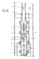
- FIG. 1A represents the upstream part of the pumping device allowing the implementation of the method according to the invention.
- This device comprises a centralizing element (1) which may or may not be sealed, the central tube (100) of which directs the mixture of gas and fluid to a first centrifugal separator (3) whose outlet (30) for discharging the gases discharges the gases in the annular space between the external cylindrical envelope (32) of the separator and the tube (11) constituting the wall of the extraction well.
- the fluid gas mixture the percentage of which has been lowered by the first separator, is discharged through an axial orifice (31) in the direction of a second separator (4) with a view to a further reduction in the percentage.
- This separator (4) evacuates the gas through an orifice (40) in the annular space and the gas fluid mixture through an axial orifice (41) in the direction of a cooling module (10) constituted by a deviating element (6) the axial flow of the separator (4) through lateral orifices (60) towards an annular space formed between an external tube (10 A) and the successive external tubes (80,90,120) respectively of the protective modules (8), motor (9) and protector (12) mounted inside and coaxially with the tube (10 A) thus forming the cooling module (10).
- the protective modules (8, 12) make it possible to ensure sealing at the level of the motor output shafts (9) upstream and downstream. In this way the motor element (9) is protected from contact with the fluids circulating in the device.
- the fluid flowing in the annular space formed between the tube (10) and the external envelopes (80,90,120) respectively forming the first protector, the motor and the second protector ensure cooling all the more efficient of the engine, that the percentage of gas in the mixture has been brought to the lowest possible level below 40%.
- a diverter module (13) allows, thanks to the orifices (130) to bring the flow axially in the separating element (14) which follows the cooling module.
- This separator (14) analogous to the other separators evacuates the gas through the orifice (140) towards the annular space between the outside of the envelope (142) of the separator device and the tubes (11) constituting the wall from the extraction well.
- This separator (14) evacuates the axial flow of the mixture to a centrifugal pump (16) through the axial orifice (141).
- the outlet of the centrifugal pump (16) is connected to a set of tubes (18) which makes it possible to raise the liquid practically separated from its gas to the surface.
- the motor (9) drives by drive shafts which extend inside the device, both towards the separators located upstream and downstream and towards the centrifugal pump.
- the two-phase mixture (2) enters the system and part of the gas is separated and discharged through the annular space at the level of the first centrifugal separator (3) with axial flow.
- the remaining mixture enters the second separator (4) where the same operation is carried out.
- the percentage of free gas at suction (2) being 99%
- the percentage at the outlet of the first separator (3) can be reduced to around 60%.
- second separator will bring the percentage of gas to around 30%.
- the fluid is thus sufficiently degassed to have sufficient heat capacity to ensure effective cooling of the engine.
- the fluid leaving the second separator (4) passes into the engine cooling module and then enters the third separator (14) to complete its journey in the centrifugal pump and then be evacuated to the surface inside the train tube (18).
- the gas on its side joins the surface through the annular space formed between the tube train (18) and the tubes (11) constituting the wall of the extraction well.
- the third separator will bring the percentage of gas from 30% at the inlet to a percentage compatible with the proper functioning of the pump (16) generally less than 8%.
- the third separator (14) is optional and depends on the percentage of gas contained in the initial two-phase liquid.
- the two separators (3,4) will be used, but the last separator (14) may possibly be dispensed with.
- only one separator (3) will be used upstream of the motor and a second separator (14) downstream of the motor.
- the drive shafts of the first and second separators (3,4) are mechanically connected in rotation by a sleeve (33).
- these shafts can be mechanically connected by an electromagnetic clutch controlled from the surface to implement, as required, one or two separator modules upstream of the engine.
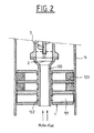
- FIG. 2 shows a sealed centering element (1) used upstream of the device.
- This centering element consists of anchoring corners (101) connected, on the one hand to the external tube (11) of the extraction well by seals (103), and on the other hand to the internal tube ( 100) for suction of the two-phase liquid (2) by seals (102), so as to channel the two-phase mixture towards the inside of the tube (100).
- the leaktight centering device (17) located downstream of the pumping device will only comprise spacers for holding the tubes (18) to allow the flow of gas outside the tube (18).
- a non-watertight centralizer (1) can be used.
- the output centering device (17) it is possible, if necessary, to use a waterproof centering device.
Landscapes
- Geology (AREA)
- Life Sciences & Earth Sciences (AREA)
- Engineering & Computer Science (AREA)
- Mining & Mineral Resources (AREA)
- Environmental & Geological Engineering (AREA)
- Fluid Mechanics (AREA)
- Physics & Mathematics (AREA)
- General Life Sciences & Earth Sciences (AREA)
- Geochemistry & Mineralogy (AREA)
- Centrifugal Separators (AREA)
- Structures Of Non-Positive Displacement Pumps (AREA)
- Gas Separation By Absorption (AREA)
- Jet Pumps And Other Pumps (AREA)
Applications Claiming Priority (2)
| Application Number | Priority Date | Filing Date | Title |
|---|---|---|---|
| FR8912759A FR2652610B1 (fr) | 1989-09-29 | 1989-09-29 | Procede de pompage de melange liquide gaz dans un puits d'extraction petrolier et dispositif de mise en óoeuvre du procede. |
| FR8912759 | 1989-09-29 |
Publications (2)
| Publication Number | Publication Date |
|---|---|
| EP0420751A1 true EP0420751A1 (de) | 1991-04-03 |
| EP0420751B1 EP0420751B1 (de) | 1993-07-21 |
Family
ID=9385947
Family Applications (1)
| Application Number | Title | Priority Date | Filing Date |
|---|---|---|---|
| EP90402660A Expired - Lifetime EP0420751B1 (de) | 1989-09-29 | 1990-09-27 | Verfahren zum Pumpen eines Gas/Flüssigkeitsgemisches aus einer Ölgewinnungsbohrung und Vorrichtung zur Durchführung des Verfahrens |
Country Status (7)
| Country | Link |
|---|---|
| US (1) | US5173022A (de) |
| EP (1) | EP0420751B1 (de) |
| BR (1) | BR9004880A (de) |
| DE (1) | DE69002296T2 (de) |
| FR (1) | FR2652610B1 (de) |
| NO (1) | NO300515B1 (de) |
| OA (1) | OA09264A (de) |
Cited By (1)
| Publication number | Priority date | Publication date | Assignee | Title |
|---|---|---|---|---|
| WO1996041065A1 (en) * | 1995-06-07 | 1996-12-19 | Centre For Engineering Research Inc. | Method for downhole cyclone separation |
Families Citing this family (17)
| Publication number | Priority date | Publication date | Assignee | Title |
|---|---|---|---|---|
| US5456837A (en) * | 1994-04-13 | 1995-10-10 | Centre For Frontier Engineering Research Institute | Multiple cyclone apparatus for downhole cyclone oil/water separation |
| US6082452A (en) * | 1996-09-27 | 2000-07-04 | Baker Hughes, Ltd. | Oil separation and pumping systems |
| AU7987298A (en) * | 1997-06-24 | 1999-01-04 | Baker Hughes Incorporated | Cyclonic separator assembly |
| US6202744B1 (en) | 1997-11-07 | 2001-03-20 | Baker Hughes Incorporated | Oil separation and pumping system and apparatus |
| US6138757A (en) * | 1998-02-24 | 2000-10-31 | Bj Services Company U.S.A. | Apparatus and method for downhole fluid phase separation |
| US6257333B1 (en) * | 1999-12-02 | 2001-07-10 | Camco International, Inc. | Reverse flow gas separator for progressing cavity submergible pumping systems |
| US7150600B1 (en) | 2002-10-31 | 2006-12-19 | Wood Group Esp, Inc. | Downhole turbomachines for handling two-phase flow |
| US7462225B1 (en) | 2004-09-15 | 2008-12-09 | Wood Group Esp, Inc. | Gas separator agitator assembly |
| US7188669B2 (en) * | 2004-10-14 | 2007-03-13 | Baker Hughes Incorporated | Motor cooler for submersible pump |
| US20060245957A1 (en) * | 2005-04-14 | 2006-11-02 | Wood Group Esp, Inc. | Encapsulated bottom intake pumping system |
| US7461692B1 (en) | 2005-12-15 | 2008-12-09 | Wood Group Esp, Inc. | Multi-stage gas separator |
| US8727016B2 (en) | 2010-12-07 | 2014-05-20 | Saudi Arabian Oil Company | Apparatus and methods for enhanced well control in slim completions |
| US8613311B2 (en) | 2011-02-20 | 2013-12-24 | Saudi Arabian Oil Company | Apparatus and methods for well completion design to avoid erosion and high friction loss for power cable deployed electric submersible pump systems |
| US9261096B2 (en) | 2011-07-29 | 2016-02-16 | Regal Beloit America, Inc. | Pump motor combination |
| US11028683B1 (en) * | 2020-12-03 | 2021-06-08 | Stoneview Solutions LLC | Downhole pump gas eliminating seating nipple system |
| WO2022170414A1 (en) | 2021-02-12 | 2022-08-18 | Drill Safe Systems Inc. | Drilling downhole regulating devices and related methods |
| US12292059B2 (en) | 2022-03-08 | 2025-05-06 | Inflow Systems Inc. | Intakes and gas separators for downhole pumps, and related apparatuses and methods |
Citations (4)
| Publication number | Priority date | Publication date | Assignee | Title |
|---|---|---|---|---|
| US1655817A (en) * | 1927-05-31 | 1928-01-10 | Hallan N Marsh | Tandem gas anchor |
| US2311963A (en) * | 1939-07-11 | 1943-02-23 | Union Oil Co | Gas anchor |
| US3282031A (en) * | 1963-06-21 | 1966-11-01 | Shell Oil Co | Centrifugal gas anchor |
| US4074763A (en) * | 1976-12-17 | 1978-02-21 | Chevron Research Company | Bottom-hole gas-liquid separator |
Family Cites Families (10)
| Publication number | Priority date | Publication date | Assignee | Title |
|---|---|---|---|---|
| US1179802A (en) * | 1911-06-26 | 1916-04-18 | American Well Works | Centrifugal pump. |
| US1700928A (en) * | 1922-08-25 | 1929-02-05 | Charles E Fawkes | Apparatus for centrifugal separation |
| US1974183A (en) * | 1929-12-23 | 1934-09-18 | Norris E Gunderson | Pump |
| US3398687A (en) * | 1963-04-06 | 1968-08-27 | Yoshikawa Yutaka | Pump device |
| US3680976A (en) * | 1970-12-14 | 1972-08-01 | Ingersoll Rand Co | Centrifugal pump having leakage collection and draining means |
| US3887342A (en) * | 1972-11-10 | 1975-06-03 | Fmc Corp | Liquid-gas separator unit |
| US4325678A (en) * | 1979-12-12 | 1982-04-20 | Hitachi, Ltd. | Hydraulic pressure producing system for a hydraulic press |
| US4481020A (en) * | 1982-06-10 | 1984-11-06 | Trw Inc. | Liquid-gas separator apparatus |
| US4632184A (en) * | 1985-10-21 | 1986-12-30 | Otis Engineering Corporation | Submersible pump safety systems |
| US4981175A (en) * | 1990-01-09 | 1991-01-01 | Conoco Inc | Recirculating gas separator for electric submersible pumps |
-
1989
- 1989-09-29 FR FR8912759A patent/FR2652610B1/fr not_active Expired - Fee Related
-
1990
- 1990-09-27 DE DE90402660T patent/DE69002296T2/de not_active Expired - Fee Related
- 1990-09-27 EP EP90402660A patent/EP0420751B1/de not_active Expired - Lifetime
- 1990-09-28 BR BR909004880A patent/BR9004880A/pt not_active IP Right Cessation
- 1990-09-28 NO NO904242A patent/NO300515B1/no not_active IP Right Cessation
- 1990-09-28 OA OA59862A patent/OA09264A/xx unknown
- 1990-10-01 US US07/591,376 patent/US5173022A/en not_active Expired - Fee Related
Patent Citations (4)
| Publication number | Priority date | Publication date | Assignee | Title |
|---|---|---|---|---|
| US1655817A (en) * | 1927-05-31 | 1928-01-10 | Hallan N Marsh | Tandem gas anchor |
| US2311963A (en) * | 1939-07-11 | 1943-02-23 | Union Oil Co | Gas anchor |
| US3282031A (en) * | 1963-06-21 | 1966-11-01 | Shell Oil Co | Centrifugal gas anchor |
| US4074763A (en) * | 1976-12-17 | 1978-02-21 | Chevron Research Company | Bottom-hole gas-liquid separator |
Cited By (1)
| Publication number | Priority date | Publication date | Assignee | Title |
|---|---|---|---|---|
| WO1996041065A1 (en) * | 1995-06-07 | 1996-12-19 | Centre For Engineering Research Inc. | Method for downhole cyclone separation |
Also Published As
| Publication number | Publication date |
|---|---|
| US5173022A (en) | 1992-12-22 |
| FR2652610A1 (fr) | 1991-04-05 |
| NO300515B1 (no) | 1997-06-09 |
| FR2652610B1 (fr) | 1992-01-03 |
| DE69002296T2 (de) | 1994-02-17 |
| OA09264A (fr) | 1992-08-31 |
| DE69002296D1 (de) | 1993-08-26 |
| NO904242L (no) | 1991-04-02 |
| EP0420751B1 (de) | 1993-07-21 |
| NO904242D0 (no) | 1990-09-28 |
| BR9004880A (pt) | 1991-09-10 |
Similar Documents
| Publication | Publication Date | Title |
|---|---|---|
| EP0420751B1 (de) | Verfahren zum Pumpen eines Gas/Flüssigkeitsgemisches aus einer Ölgewinnungsbohrung und Vorrichtung zur Durchführung des Verfahrens | |
| CA2204664C (fr) | Systeme de pompage polyphasique et centrifuge | |
| FR2774136A1 (fr) | Dispositif de compression-pompage monoarbre associe a un separateur | |
| EP0096636B1 (de) | System zur Gewinnung von Fluida aus einer Lagerstätte | |
| FR2497319A1 (fr) | Soupape de derivation avec alarme | |
| FR2505680A1 (fr) | Appareil et procede pour la concentration des boues | |
| US20110236233A1 (en) | Double Sealing Labyrinth Chamber for Use With a Downhole Electrical Submersible Pump | |
| FR2919206A1 (fr) | Separateur a ecoulement cyclonique | |
| EP0457879B1 (de) | Vorrichtung und verfahren zur reinigung eines unterirdischen bohrloches | |
| CH669641A5 (de) | ||
| CA2251611C (fr) | Installation de pompage d'un effluent biphasique liquide/gaz | |
| EP0435716B1 (de) | Vorrichtung zur Separation eines Gas-Flüssigkeitsgemisches als Zufuhr einer Imbohrlochpumpe | |
| EP0065922A1 (de) | Primärpumpe für einen Druckwasserreaktor, mit einem Dichtungssystem für ihre Antriebswelle | |
| EP0694676A1 (de) | Einrichtung für Erdöl-Produktionsbohrung | |
| EP0989306B1 (de) | Kompressor und Pumpensystem mit alternierendem Betrieb des Kompressorteils und zugehörigem Verfahren | |
| EP0097548B1 (de) | Bohrlochpumpe und Verfahren zu ihrem Schutz | |
| FR2517020A1 (fr) | Dispositif d'evacuation de purge | |
| FR2656035A1 (fr) | Dispositif de pompage d'un liquide et en particulier d'un liquide a forte viscosite. | |
| EP0287622A1 (de) | Abfüllanlage | |
| FR2621083A1 (fr) | Pompe immergee de prelevement de liquide dans une conduite, notamment une conduite de rejet en eau profonde d'eaux de refroidissement de centrale nucleaire | |
| FR2697870A1 (fr) | Pompe axiale à faible débit. | |
| FR2667116A1 (fr) | Dispositif de pompage d'un fluide polyphasique. | |
| FR2601084A1 (fr) | Pompe centrifuge pour le refoulement de fluides contenant des gaz | |
| FR2492011A1 (fr) | Procedes pour deplacer des boues et pompe pour leur mise en oeuvre | |
| FR2964885A1 (fr) | Dispositif perfectionne de filtration d'hydrocarbure |
Legal Events
| Date | Code | Title | Description |
|---|---|---|---|
| PUAI | Public reference made under article 153(3) epc to a published international application that has entered the european phase |
Free format text: ORIGINAL CODE: 0009012 |
|
| 17P | Request for examination filed |
Effective date: 19901002 |
|
| AK | Designated contracting states |
Kind code of ref document: A1 Designated state(s): DE FR GB IT NL |
|
| 17Q | First examination report despatched |
Effective date: 19920930 |
|
| RAP1 | Party data changed (applicant data changed or rights of an application transferred) |
Owner name: ELF AQUITAINE PRODUCTION |
|
| GRAA | (expected) grant |
Free format text: ORIGINAL CODE: 0009210 |
|
| AK | Designated contracting states |
Kind code of ref document: B1 Designated state(s): DE FR GB IT NL |
|
| REF | Corresponds to: |
Ref document number: 69002296 Country of ref document: DE Date of ref document: 19930826 |
|
| ITF | It: translation for a ep patent filed | ||
| GBT | Gb: translation of ep patent filed (gb section 77(6)(a)/1977) |
Effective date: 19931022 |
|
| PLBE | No opposition filed within time limit |
Free format text: ORIGINAL CODE: 0009261 |
|
| STAA | Information on the status of an ep patent application or granted ep patent |
Free format text: STATUS: NO OPPOSITION FILED WITHIN TIME LIMIT |
|
| 26N | No opposition filed | ||
| REG | Reference to a national code |
Ref country code: FR Ref legal event code: TP |
|
| PGFP | Annual fee paid to national office [announced via postgrant information from national office to epo] |
Ref country code: NL Payment date: 20000829 Year of fee payment: 11 |
|
| PGFP | Annual fee paid to national office [announced via postgrant information from national office to epo] |
Ref country code: DE Payment date: 20000830 Year of fee payment: 11 |
|
| PGFP | Annual fee paid to national office [announced via postgrant information from national office to epo] |
Ref country code: GB Payment date: 20000831 Year of fee payment: 11 |
|
| PGFP | Annual fee paid to national office [announced via postgrant information from national office to epo] |
Ref country code: FR Payment date: 20000928 Year of fee payment: 11 |
|
| PG25 | Lapsed in a contracting state [announced via postgrant information from national office to epo] |
Ref country code: GB Free format text: LAPSE BECAUSE OF NON-PAYMENT OF DUE FEES Effective date: 20010927 |
|
| REG | Reference to a national code |
Ref country code: GB Ref legal event code: IF02 |
|
| PG25 | Lapsed in a contracting state [announced via postgrant information from national office to epo] |
Ref country code: NL Free format text: LAPSE BECAUSE OF NON-PAYMENT OF DUE FEES Effective date: 20020401 |
|
| PG25 | Lapsed in a contracting state [announced via postgrant information from national office to epo] |
Ref country code: DE Free format text: LAPSE BECAUSE OF NON-PAYMENT OF DUE FEES Effective date: 20020501 |
|
| GBPC | Gb: european patent ceased through non-payment of renewal fee |
Effective date: 20010927 |
|
| PG25 | Lapsed in a contracting state [announced via postgrant information from national office to epo] |
Ref country code: FR Free format text: LAPSE BECAUSE OF NON-PAYMENT OF DUE FEES Effective date: 20020531 |
|
| NLV4 | Nl: lapsed or anulled due to non-payment of the annual fee |
Effective date: 20020401 |
|
| REG | Reference to a national code |
Ref country code: FR Ref legal event code: ST |
|
| NLV4 | Nl: lapsed or anulled due to non-payment of the annual fee |
Effective date: 20020401 |
|
| PG25 | Lapsed in a contracting state [announced via postgrant information from national office to epo] |
Ref country code: IT Free format text: LAPSE BECAUSE OF NON-PAYMENT OF DUE FEES Effective date: 20050927 |