EP0420797A2 - Cale pour coffrages à béton - Google Patents
Cale pour coffrages à béton Download PDFInfo
- Publication number
- EP0420797A2 EP0420797A2 EP90810670A EP90810670A EP0420797A2 EP 0420797 A2 EP0420797 A2 EP 0420797A2 EP 90810670 A EP90810670 A EP 90810670A EP 90810670 A EP90810670 A EP 90810670A EP 0420797 A2 EP0420797 A2 EP 0420797A2
- Authority
- EP
- European Patent Office
- Prior art keywords
- stop body
- nail
- sleeve
- abutment
- abutment piece
- Prior art date
- Legal status (The legal status is an assumption and is not a legal conclusion. Google has not performed a legal analysis and makes no representation as to the accuracy of the status listed.)
- Granted
Links
Images
Classifications
-
- E—FIXED CONSTRUCTIONS
- E04—BUILDING
- E04G—SCAFFOLDING; FORMS; SHUTTERING; BUILDING IMPLEMENTS OR AIDS, OR THEIR USE; HANDLING BUILDING MATERIALS ON THE SITE; REPAIRING, BREAKING-UP OR OTHER WORK ON EXISTING BUILDINGS
- E04G17/00—Connecting or other auxiliary members for forms, falsework structures, or shutterings
- E04G17/06—Tying means; Spacers ; Devices for extracting or inserting wall ties
- E04G17/064—Spacers placed on the bottom of the mould
-
- E—FIXED CONSTRUCTIONS
- E04—BUILDING
- E04G—SCAFFOLDING; FORMS; SHUTTERING; BUILDING IMPLEMENTS OR AIDS, OR THEIR USE; HANDLING BUILDING MATERIALS ON THE SITE; REPAIRING, BREAKING-UP OR OTHER WORK ON EXISTING BUILDINGS
- E04G17/00—Connecting or other auxiliary members for forms, falsework structures, or shutterings
- E04G17/14—Bracing or strutting arrangements for formwalls; Devices for aligning forms
-
- F—MECHANICAL ENGINEERING; LIGHTING; HEATING; WEAPONS; BLASTING
- F16—ENGINEERING ELEMENTS AND UNITS; GENERAL MEASURES FOR PRODUCING AND MAINTAINING EFFECTIVE FUNCTIONING OF MACHINES OR INSTALLATIONS; THERMAL INSULATION IN GENERAL
- F16B—DEVICES FOR FASTENING OR SECURING CONSTRUCTIONAL ELEMENTS OR MACHINE PARTS TOGETHER, e.g. NAILS, BOLTS, CIRCLIPS, CLAMPS, CLIPS OR WEDGES; JOINTS OR JOINTING
- F16B19/00—Bolts without screw-thread; Pins, including deformable elements; Rivets
- F16B19/14—Bolts or the like for shooting into concrete constructions, metal walls or the like by means of detonation-operated nailing tools
-
- F—MECHANICAL ENGINEERING; LIGHTING; HEATING; WEAPONS; BLASTING
- F16—ENGINEERING ELEMENTS AND UNITS; GENERAL MEASURES FOR PRODUCING AND MAINTAINING EFFECTIVE FUNCTIONING OF MACHINES OR INSTALLATIONS; THERMAL INSULATION IN GENERAL
- F16B—DEVICES FOR FASTENING OR SECURING CONSTRUCTIONAL ELEMENTS OR MACHINE PARTS TOGETHER, e.g. NAILS, BOLTS, CIRCLIPS, CLAMPS, CLIPS OR WEDGES; JOINTS OR JOINTING
- F16B43/00—Washers or equivalent devices; Other devices for supporting bolt-heads or nuts
-
- Y—GENERAL TAGGING OF NEW TECHNOLOGICAL DEVELOPMENTS; GENERAL TAGGING OF CROSS-SECTIONAL TECHNOLOGIES SPANNING OVER SEVERAL SECTIONS OF THE IPC; TECHNICAL SUBJECTS COVERED BY FORMER USPC CROSS-REFERENCE ART COLLECTIONS [XRACs] AND DIGESTS
- Y10—TECHNICAL SUBJECTS COVERED BY FORMER USPC
- Y10S—TECHNICAL SUBJECTS COVERED BY FORMER USPC CROSS-REFERENCE ART COLLECTIONS [XRACs] AND DIGESTS
- Y10S411/00—Expanded, threaded, driven, headed, tool-deformed, or locked-threaded fastener
- Y10S411/904—Fastener or fastener element composed of nonmetallic material
- Y10S411/908—Resinous material
Definitions
- the invention relates to a stop body for concrete formwork, with a passage opening and abutment for a nail, a crumple zone being provided between the abutment and the stop body.
- a stop body which is provided for the lateral support of concrete formwork and is attached to a component by means of a nail.
- a passage opening and an abutment are provided for the nail, a crumple zone being arranged between the abutment and the stop body.
- the crumple zone acts as a shock absorber and prevents damage to the stop body.
- the crumple zone is formed by a ring that is slidably seated on the nail, the end of which serves as an abutment.
- the nail must be fitted with the ring before insertion into the passage opening of the stop body, which proves to be cumbersome. There is also a risk of forgetting to apply the ring to the nail.
- a disadvantage of the known arrangement is above all that the ring tears open radially during the compression and falls off the shaft of the nail. As a result, the support of the stop body by the nail is lost.
- the invention has for its object to provide a stop body with abutment and crumple zone, which ensures easy handling and safe function.
- the object is achieved in that the crumple zone is designed as a compressible part which is integrally connected to the stop body.
- the compressible part can also with possible radial tearing do not jump off, so that the safe functioning of the stop body is guaranteed.
- the one-piece connection is preferably made in that the compressible part is molded directly onto the stop body.
- the compressible part connected to the stop body in this way is thus available such that after the stop body has been placed on the component, only the nail has to be driven into the component through the passage opening. If this is done using a powder-operated setting tool, it can be supported laterally on the muzzle side of the compressible part, which has particular advantages in terms of handling.
- the compressible part is preferably designed as a free-standing sleeve.
- the sleeve can protrude from a support surface of the stop body facing the abutment. In the event of excess energy, the forces introduced by the nail onto the abutment are introduced directly into the component via the stop body, the sleeve being axially compressed in accordance with the excess energy.
- the free end of the sleeve is advantageously set back axially with respect to the outer contour of the stop body. This ensures that the driven nail does not project axially beyond the stop body. In this way it is avoided that the concrete formwork at most strikes the nail when approaching the stop body, which could lead to a load impairing the anchoring of the nail.
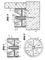
- the stop body 1 is made of plastic and is integrally connected to a sleeve 2 serving as a crumple zone.
- a stop opening 3 passes through the stop body 1 and the sleeve 2.
- the sleeve 2 sits on a hub-like inner part 4 of the stop body 1, which is connected by a base part 5 to an essentially hollow cylindrical jacket part 6.
- ribs 7 are provided between the base part 5 and the jacket part 6, as illustrated in FIG. 2.
- the free-standing end of the sleeve 2 serves as an abutment 8 and is set back by approximately the diameter of the sleeve 2 relative to the outer contour of the jacket part 6.
- the other end face of the jacket part 6 has a plurality of support fingers 9 distributed over the circumference.
- a stop body 1 is fastened to a component 11, for example made of concrete, in order to laterally support a concrete formwork 12.
- the support fingers 9 ensure stable support of the stop body 1 even in the event of any unevenness in the top of the component 11.
- a nail 13 has been driven into the component 11 through the passage opening 3.
- the driving in of the nail 13, which is preferably carried out with the aid of a powder-operated setting tool, can, depending on the strength of the component 11 in the area of the driving-in point, lead from fastening point to fastening point to driving the nail 13 to different depths.
- the head 13a of the nail 13 running towards the end of the driving-in process on the abutment 8 displaces the abutment 8 in the driving-in direction, the sleeve 2, as shown in FIG. 3, is axially compressed.
- the head 13a remains in contact with the abutment 8, so that the stop body 1 is held against the component 11 via the compressed sleeve 2 connected to the inner part 4.
- the upsetting of the sleeve 2 also contributes to the reduction of the excess energy imparted to the nail 13.
Landscapes
- Engineering & Computer Science (AREA)
- General Engineering & Computer Science (AREA)
- Mechanical Engineering (AREA)
- Architecture (AREA)
- Civil Engineering (AREA)
- Structural Engineering (AREA)
- Forms Removed On Construction Sites Or Auxiliary Members Thereof (AREA)
- Portable Nailing Machines And Staplers (AREA)
- Organic Low-Molecular-Weight Compounds And Preparation Thereof (AREA)
Priority Applications (1)
| Application Number | Priority Date | Filing Date | Title |
|---|---|---|---|
| AT90810670T ATE98732T1 (de) | 1989-09-23 | 1990-09-05 | Anschlagkoerper fuer betonschalungen. |
Applications Claiming Priority (2)
| Application Number | Priority Date | Filing Date | Title |
|---|---|---|---|
| DE3931831A DE3931831A1 (de) | 1989-09-23 | 1989-09-23 | Anschlagkoerper fuer betonschalungen |
| DE3931831 | 1989-09-23 |
Publications (3)
| Publication Number | Publication Date |
|---|---|
| EP0420797A2 true EP0420797A2 (fr) | 1991-04-03 |
| EP0420797A3 EP0420797A3 (en) | 1991-08-28 |
| EP0420797B1 EP0420797B1 (fr) | 1993-12-15 |
Family
ID=6390061
Family Applications (1)
| Application Number | Title | Priority Date | Filing Date |
|---|---|---|---|
| EP90810670A Expired - Lifetime EP0420797B1 (fr) | 1989-09-23 | 1990-09-05 | Cale pour coffrages à béton |
Country Status (5)
| Country | Link |
|---|---|
| US (1) | US5125616A (fr) |
| EP (1) | EP0420797B1 (fr) |
| AT (1) | ATE98732T1 (fr) |
| CA (1) | CA2025923C (fr) |
| DE (2) | DE3931831A1 (fr) |
Cited By (5)
| Publication number | Priority date | Publication date | Assignee | Title |
|---|---|---|---|---|
| EP0676551A3 (fr) * | 1994-04-09 | 1996-10-30 | Hilti Ag | Dispositif de fixation pour l'enfoncement dans des matériaux durs au moyen d'appareils de scellement à actionnement pyrotechnique. |
| EP0875643A1 (fr) | 1997-05-03 | 1998-11-04 | HILTI Aktiengesellschaft | Positionneur de coffrage |
| DE29812111U1 (de) * | 1998-07-09 | 1999-11-18 | Adolf Würth GmbH & Co. KG, 74653 Künzelsau | Schalungsanschlag |
| EP1538345A1 (fr) * | 2003-12-01 | 2005-06-08 | HILTI Aktiengesellschaft | Elément auxiliaire de construction |
| DE202009006026U1 (de) | 2009-04-22 | 2009-07-02 | Adolf Würth GmbH & Co. KG | Anschlagkörper für Betonschalungen |
Families Citing this family (15)
| Publication number | Priority date | Publication date | Assignee | Title |
|---|---|---|---|---|
| US5332191A (en) * | 1992-10-26 | 1994-07-26 | Nolan Terry L | Apparatus for making concrete slabs |
| DE4318965C2 (de) * | 1993-06-08 | 1996-04-11 | Hilti Ag | Verfahren zum Setzen von Befestigungselementen |
| DE19505841A1 (de) * | 1995-02-21 | 1996-08-22 | Hilti Ag | Befestigungselement zum Befestigen von Platten großer Dicke an Bauteilen |
| US7004704B1 (en) * | 2004-09-30 | 2006-02-28 | Illinois Tool Works Inc. | Flute positioner |
| FR2883341B1 (fr) * | 2005-03-18 | 2007-06-29 | Prospection Et D Inv S Techniq | Ensemble d'une embase et d'un tampon de fixation |
| US7654784B2 (en) * | 2006-01-31 | 2010-02-02 | Honeywell International Inc. | Device housing with integral fastener retainers |
| MXPA06003044A (es) * | 2006-03-17 | 2007-09-17 | Juan Antonio Ferro De La Cruz | Dispositivo para la alineacion de cimbras modulares en muros de concreto. |
| US20080315065A1 (en) * | 2007-06-22 | 2008-12-25 | Hanson Troy A | Bracket assembly for facilitating the installation of a concrete wall on a concrete footing and a method of forming the wall |
| US8348226B2 (en) * | 2007-06-22 | 2013-01-08 | Hanson Troy A | Bracket assembly for facilitation the installation of a concrete wall on a concrete footing and a method of forming the wall |
| DE102008001170A1 (de) * | 2008-04-14 | 2009-10-15 | Hilti Aktiengesellschaft | Anschlagkörper für Betonschalungen |
| DE102009028119A1 (de) * | 2009-07-30 | 2011-02-03 | Hilti Aktiengesellschaft | Anschlagkörper |
| RU167465U1 (ru) * | 2016-08-04 | 2017-01-10 | Дмитрий Витальевич Гвидонский | Шайба электроизоляционная для рельсового скрепления |
| CH713432A2 (de) * | 2017-02-01 | 2018-08-15 | Albanese Pino | Verfahren zum Verbinden eines Distanzhalterstabs mit einem Anschlusseisen an einer Teilbaute, sowie einen Keil, eine Abstand- und Anschlaghalteranordnung und ein Halter. |
| USD913081S1 (en) | 2019-05-29 | 2021-03-16 | The Boeing Company | Structural spacer member |
| US11059586B2 (en) * | 2019-05-29 | 2021-07-13 | The Boeing Company | Structural spacer members |
Family Cites Families (12)
| Publication number | Priority date | Publication date | Assignee | Title |
|---|---|---|---|---|
| US2092684A (en) * | 1935-01-18 | 1937-09-07 | Timber Engineering Co | Shear plate |
| US2614310A (en) * | 1948-08-21 | 1952-10-21 | James Robert Maxwell | Undercut former |
| US3382751A (en) * | 1966-01-12 | 1968-05-14 | Olin Mathieson | Fastener and attachment for pistontype fastening tool |
| US3469817A (en) * | 1967-10-20 | 1969-09-30 | Symons Mfg Co | Hole-pattern member for use in connection with a concrete floor slab form |
| FR2260018A1 (en) * | 1974-02-05 | 1975-08-29 | Olin Corp | Impact dowel and fixing braket - dowel fired from "nail gun" retains bracket against surface |
| US4077599A (en) * | 1975-02-18 | 1978-03-07 | Oland John H | Device for forming apertures in concrete |
| US4289060A (en) * | 1977-10-03 | 1981-09-15 | Hooker Chemicals & Plastics Corp. | Device and assembly for mounting parts |
| FR2451434A1 (fr) * | 1979-03-15 | 1980-10-10 | Laroche Jean Pierre | Element de construction |
| US4669169A (en) * | 1981-05-29 | 1987-06-02 | Anchor Wire Corporation Of Tennessee | Method of mounting an article to a substrate |
| GB8612003D0 (en) * | 1986-05-16 | 1986-06-25 | Dunlop Construction Products I | Attaching sheet material to substrate |
| DE3707424A1 (de) * | 1987-03-07 | 1988-09-15 | Hilti Ag | Befestigungselement mit nagel und huelse |
| DE3743049A1 (de) * | 1987-12-18 | 1989-06-29 | Hilti Ag | Nagel mit stauchbarer huelse |
-
1989
- 1989-09-23 DE DE3931831A patent/DE3931831A1/de not_active Withdrawn
-
1990
- 1990-09-05 AT AT90810670T patent/ATE98732T1/de not_active IP Right Cessation
- 1990-09-05 EP EP90810670A patent/EP0420797B1/fr not_active Expired - Lifetime
- 1990-09-05 DE DE90810670T patent/DE59003869D1/de not_active Expired - Lifetime
- 1990-09-21 CA CA002025923A patent/CA2025923C/fr not_active Expired - Fee Related
- 1990-09-24 US US07/587,238 patent/US5125616A/en not_active Expired - Lifetime
Cited By (6)
| Publication number | Priority date | Publication date | Assignee | Title |
|---|---|---|---|---|
| EP0676551A3 (fr) * | 1994-04-09 | 1996-10-30 | Hilti Ag | Dispositif de fixation pour l'enfoncement dans des matériaux durs au moyen d'appareils de scellement à actionnement pyrotechnique. |
| EP0875643A1 (fr) | 1997-05-03 | 1998-11-04 | HILTI Aktiengesellschaft | Positionneur de coffrage |
| DE29812111U1 (de) * | 1998-07-09 | 1999-11-18 | Adolf Würth GmbH & Co. KG, 74653 Künzelsau | Schalungsanschlag |
| EP0971084A1 (fr) * | 1998-07-09 | 2000-01-12 | Adolf Würth GmbH & Co. KG | Cale pour coffrage |
| EP1538345A1 (fr) * | 2003-12-01 | 2005-06-08 | HILTI Aktiengesellschaft | Elément auxiliaire de construction |
| DE202009006026U1 (de) | 2009-04-22 | 2009-07-02 | Adolf Würth GmbH & Co. KG | Anschlagkörper für Betonschalungen |
Also Published As
| Publication number | Publication date |
|---|---|
| DE3931831A1 (de) | 1991-04-04 |
| CA2025923A1 (fr) | 1991-03-24 |
| US5125616A (en) | 1992-06-30 |
| DE59003869D1 (de) | 1994-01-27 |
| EP0420797A3 (en) | 1991-08-28 |
| EP0420797B1 (fr) | 1993-12-15 |
| ATE98732T1 (de) | 1994-01-15 |
| CA2025923C (fr) | 1998-09-29 |
Similar Documents
| Publication | Publication Date | Title |
|---|---|---|
| EP0420797B1 (fr) | Cale pour coffrages à béton | |
| EP0308620B1 (fr) | Piston à expansion | |
| EP0420799B1 (fr) | Elément de fixation pour panneaux d'isolation | |
| EP0282445B1 (fr) | Elément de fixation avec clou et douille | |
| DE2607338C2 (de) | Schlagdübel mit Spreizhülse und Spreizelement | |
| DE2733007C2 (de) | Klebeanker | |
| EP1134435B1 (fr) | Cheville | |
| DE3507022A1 (de) | Spreizduebel mit setzanzeige | |
| EP0540463B1 (fr) | Clou avec chemise et rondelle | |
| DE3335628A1 (de) | Spreizduebel mit einziehbarem spreizkoerper | |
| EP0702159A2 (fr) | Clou projectile muni d'une douille compressible | |
| CH617484A5 (fr) | ||
| DE2206088A1 (de) | Ankervorrichtung nach art einer ankerschraube oder eines ankerbolzens | |
| EP0713014A2 (fr) | Boulon de scellement par du mortier | |
| DE2547634A1 (de) | Sicherheitsduebel | |
| CH641712A5 (de) | Verfahren zum setzen von befestigungselementen in harte aufnahmematerialien. | |
| DE19542949A1 (de) | Bolzen zum Eintreiben in harte Aufnahmewerkstoffe | |
| EP0612924B1 (fr) | Cheville à expansion avec manchon et élément d'expansion | |
| EP0728882B1 (fr) | Elément de fixation pour plaques d'épaisseur élévée sur des éléments de construction | |
| EP0669472B1 (fr) | Elément de fixation pour l'enforcement dans des matériaux durs au moyen d'un outil actionné par la poudre | |
| EP0406801A1 (fr) | Dispositif de fixation | |
| EP1013944A2 (fr) | Elément de fixation | |
| EP1650445B1 (fr) | Dispositif de fixation pour panneaux isolants | |
| EP0272388A2 (fr) | Chaussure, en particulier chaussure de dames à talons hauts | |
| DE3620573A1 (de) | Vorrichtung zum befestigen eines gegenstandes an einer wand oder dgl. |
Legal Events
| Date | Code | Title | Description |
|---|---|---|---|
| PUAI | Public reference made under article 153(3) epc to a published international application that has entered the european phase |
Free format text: ORIGINAL CODE: 0009012 |
|
| AK | Designated contracting states |
Kind code of ref document: A2 Designated state(s): AT BE CH DE FR GB LI SE |
|
| PUAL | Search report despatched |
Free format text: ORIGINAL CODE: 0009013 |
|
| AK | Designated contracting states |
Kind code of ref document: A3 Designated state(s): AT BE CH DE FR GB LI SE |
|
| 17P | Request for examination filed |
Effective date: 19910926 |
|
| 17Q | First examination report despatched |
Effective date: 19920817 |
|
| GRAA | (expected) grant |
Free format text: ORIGINAL CODE: 0009210 |
|
| AK | Designated contracting states |
Kind code of ref document: B1 Designated state(s): AT BE CH DE FR GB LI SE |
|
| REF | Corresponds to: |
Ref document number: 98732 Country of ref document: AT Date of ref document: 19940115 Kind code of ref document: T |
|
| REF | Corresponds to: |
Ref document number: 59003869 Country of ref document: DE Date of ref document: 19940127 |
|
| ET | Fr: translation filed | ||
| GBT | Gb: translation of ep patent filed (gb section 77(6)(a)/1977) |
Effective date: 19940120 |
|
| PLBE | No opposition filed within time limit |
Free format text: ORIGINAL CODE: 0009261 |
|
| STAA | Information on the status of an ep patent application or granted ep patent |
Free format text: STATUS: NO OPPOSITION FILED WITHIN TIME LIMIT |
|
| 26N | No opposition filed | ||
| EAL | Se: european patent in force in sweden |
Ref document number: 90810670.1 |
|
| PGFP | Annual fee paid to national office [announced via postgrant information from national office to epo] |
Ref country code: GB Payment date: 20010905 Year of fee payment: 12 |
|
| PGFP | Annual fee paid to national office [announced via postgrant information from national office to epo] |
Ref country code: SE Payment date: 20010906 Year of fee payment: 12 |
|
| PGFP | Annual fee paid to national office [announced via postgrant information from national office to epo] |
Ref country code: BE Payment date: 20011105 Year of fee payment: 12 |
|
| REG | Reference to a national code |
Ref country code: GB Ref legal event code: IF02 |
|
| PG25 | Lapsed in a contracting state [announced via postgrant information from national office to epo] |
Ref country code: GB Free format text: LAPSE BECAUSE OF NON-PAYMENT OF DUE FEES Effective date: 20020905 |
|
| PG25 | Lapsed in a contracting state [announced via postgrant information from national office to epo] |
Ref country code: SE Free format text: LAPSE BECAUSE OF NON-PAYMENT OF DUE FEES Effective date: 20020906 |
|
| PG25 | Lapsed in a contracting state [announced via postgrant information from national office to epo] |
Ref country code: BE Free format text: LAPSE BECAUSE OF NON-PAYMENT OF DUE FEES Effective date: 20020930 |
|
| BERE | Be: lapsed |
Owner name: *HILTI A.G. Effective date: 20020930 |
|
| GBPC | Gb: european patent ceased through non-payment of renewal fee |
Effective date: 20020905 |
|
| EUG | Se: european patent has lapsed | ||
| PGFP | Annual fee paid to national office [announced via postgrant information from national office to epo] |
Ref country code: AT Payment date: 20050913 Year of fee payment: 16 |
|
| PGFP | Annual fee paid to national office [announced via postgrant information from national office to epo] |
Ref country code: CH Payment date: 20050914 Year of fee payment: 16 |
|
| PG25 | Lapsed in a contracting state [announced via postgrant information from national office to epo] |
Ref country code: AT Free format text: LAPSE BECAUSE OF NON-PAYMENT OF DUE FEES Effective date: 20060905 |
|
| PG25 | Lapsed in a contracting state [announced via postgrant information from national office to epo] |
Ref country code: LI Free format text: LAPSE BECAUSE OF NON-PAYMENT OF DUE FEES Effective date: 20060930 Ref country code: CH Free format text: LAPSE BECAUSE OF NON-PAYMENT OF DUE FEES Effective date: 20060930 |
|
| REG | Reference to a national code |
Ref country code: CH Ref legal event code: PL |
|
| PGFP | Annual fee paid to national office [announced via postgrant information from national office to epo] |
Ref country code: FR Payment date: 20080915 Year of fee payment: 19 |
|
| PGFP | Annual fee paid to national office [announced via postgrant information from national office to epo] |
Ref country code: DE Payment date: 20090814 Year of fee payment: 20 |
|
| REG | Reference to a national code |
Ref country code: FR Ref legal event code: ST Effective date: 20100531 |
|
| PG25 | Lapsed in a contracting state [announced via postgrant information from national office to epo] |
Ref country code: FR Free format text: LAPSE BECAUSE OF NON-PAYMENT OF DUE FEES Effective date: 20090930 |
|
| PG25 | Lapsed in a contracting state [announced via postgrant information from national office to epo] |
Ref country code: DE Free format text: LAPSE BECAUSE OF EXPIRATION OF PROTECTION Effective date: 20100905 |