EP0420820A1 - Procédé et dispositif pour enfiler du fil dans une station de coupe d'une presse de formage - Google Patents
Procédé et dispositif pour enfiler du fil dans une station de coupe d'une presse de formage Download PDFInfo
- Publication number
- EP0420820A1 EP0420820A1 EP90810734A EP90810734A EP0420820A1 EP 0420820 A1 EP0420820 A1 EP 0420820A1 EP 90810734 A EP90810734 A EP 90810734A EP 90810734 A EP90810734 A EP 90810734A EP 0420820 A1 EP0420820 A1 EP 0420820A1
- Authority
- EP
- European Patent Office
- Prior art keywords
- drive
- raw material
- torque
- feed roller
- feed
- Prior art date
- Legal status (The legal status is an assumption and is not a legal conclusion. Google has not performed a legal analysis and makes no representation as to the accuracy of the status listed.)
- Granted
Links
- 238000000034 method Methods 0.000 title claims abstract description 15
- 238000005520 cutting process Methods 0.000 title claims description 5
- 230000008569 process Effects 0.000 title description 3
- 239000002994 raw material Substances 0.000 claims abstract description 32
- 230000033001 locomotion Effects 0.000 claims abstract description 11
- 239000000463 material Substances 0.000 claims description 19
- 230000007246 mechanism Effects 0.000 claims description 8
- 238000012806 monitoring device Methods 0.000 claims 1
- 238000010008 shearing Methods 0.000 description 8
- 230000005540 biological transmission Effects 0.000 description 5
- 230000006378 damage Effects 0.000 description 5
- 208000027418 Wounds and injury Diseases 0.000 description 4
- 208000014674 injury Diseases 0.000 description 4
- 238000005452 bending Methods 0.000 description 3
- 230000008901 benefit Effects 0.000 description 3
- 230000008878 coupling Effects 0.000 description 3
- 238000010168 coupling process Methods 0.000 description 3
- 238000005859 coupling reaction Methods 0.000 description 3
- 238000012544 monitoring process Methods 0.000 description 3
- 238000000926 separation method Methods 0.000 description 3
- 230000015572 biosynthetic process Effects 0.000 description 2
- 230000000694 effects Effects 0.000 description 2
- 238000007731 hot pressing Methods 0.000 description 2
- 238000012423 maintenance Methods 0.000 description 2
- 238000004519 manufacturing process Methods 0.000 description 2
- 230000006835 compression Effects 0.000 description 1
- 238000007906 compression Methods 0.000 description 1
- 238000001816 cooling Methods 0.000 description 1
- 230000001419 dependent effect Effects 0.000 description 1
- 230000002349 favourable effect Effects 0.000 description 1
- 230000017525 heat dissipation Effects 0.000 description 1
- 230000003993 interaction Effects 0.000 description 1
- 230000033764 rhythmic process Effects 0.000 description 1
- 238000007790 scraping Methods 0.000 description 1
- 230000007704 transition Effects 0.000 description 1
Images

Classifications
-
- B—PERFORMING OPERATIONS; TRANSPORTING
- B21—MECHANICAL METAL-WORKING WITHOUT ESSENTIALLY REMOVING MATERIAL; PUNCHING METAL
- B21D—WORKING OR PROCESSING OF SHEET METAL OR METAL TUBES, RODS OR PROFILES WITHOUT ESSENTIALLY REMOVING MATERIAL; PUNCHING METAL
- B21D43/00—Feeding, positioning or storing devices combined with, or arranged in, or specially adapted for use in connection with, apparatus for working or processing sheet metal, metal tubes or metal profiles; Associations therewith of cutting devices
- B21D43/02—Advancing work in relation to the stroke of the die or tool
- B21D43/04—Advancing work in relation to the stroke of the die or tool by means in mechanical engagement with the work
- B21D43/08—Advancing work in relation to the stroke of the die or tool by means in mechanical engagement with the work by rollers
- B21D43/09—Advancing work in relation to the stroke of the die or tool by means in mechanical engagement with the work by rollers by one or more pairs of rollers for feeding sheet or strip material
-
- B—PERFORMING OPERATIONS; TRANSPORTING
- B21—MECHANICAL METAL-WORKING WITHOUT ESSENTIALLY REMOVING MATERIAL; PUNCHING METAL
- B21D—WORKING OR PROCESSING OF SHEET METAL OR METAL TUBES, RODS OR PROFILES WITHOUT ESSENTIALLY REMOVING MATERIAL; PUNCHING METAL
- B21D43/00—Feeding, positioning or storing devices combined with, or arranged in, or specially adapted for use in connection with, apparatus for working or processing sheet metal, metal tubes or metal profiles; Associations therewith of cutting devices
- B21D43/02—Advancing work in relation to the stroke of the die or tool
- B21D43/021—Control or correction devices in association with moving strips
-
- B—PERFORMING OPERATIONS; TRANSPORTING
- B21—MECHANICAL METAL-WORKING WITHOUT ESSENTIALLY REMOVING MATERIAL; PUNCHING METAL
- B21D—WORKING OR PROCESSING OF SHEET METAL OR METAL TUBES, RODS OR PROFILES WITHOUT ESSENTIALLY REMOVING MATERIAL; PUNCHING METAL
- B21D43/00—Feeding, positioning or storing devices combined with, or arranged in, or specially adapted for use in connection with, apparatus for working or processing sheet metal, metal tubes or metal profiles; Associations therewith of cutting devices
- B21D43/28—Associations of cutting devices therewith
- B21D43/285—Devices for handling elongated articles, e.g. bars, tubes or profiles
-
- B—PERFORMING OPERATIONS; TRANSPORTING
- B23—MACHINE TOOLS; METAL-WORKING NOT OTHERWISE PROVIDED FOR
- B23D—PLANING; SLOTTING; SHEARING; BROACHING; SAWING; FILING; SCRAPING; LIKE OPERATIONS FOR WORKING METAL BY REMOVING MATERIAL, NOT OTHERWISE PROVIDED FOR
- B23D33/00—Accessories for shearing machines or shearing devices
- B23D33/006—Accessories for shearing machines or shearing devices for obtaining pieces of a predetermined length, e.g. control arrangements
-
- B—PERFORMING OPERATIONS; TRANSPORTING
- B23—MACHINE TOOLS; METAL-WORKING NOT OTHERWISE PROVIDED FOR
- B23D—PLANING; SLOTTING; SHEARING; BROACHING; SAWING; FILING; SCRAPING; LIKE OPERATIONS FOR WORKING METAL BY REMOVING MATERIAL, NOT OTHERWISE PROVIDED FOR
- B23D33/00—Accessories for shearing machines or shearing devices
- B23D33/02—Arrangements for holding, guiding, and/or feeding work during the operation
-
- B—PERFORMING OPERATIONS; TRANSPORTING
- B23—MACHINE TOOLS; METAL-WORKING NOT OTHERWISE PROVIDED FOR
- B23D—PLANING; SLOTTING; SHEARING; BROACHING; SAWING; FILING; SCRAPING; LIKE OPERATIONS FOR WORKING METAL BY REMOVING MATERIAL, NOT OTHERWISE PROVIDED FOR
- B23D33/00—Accessories for shearing machines or shearing devices
- B23D33/10—Stops for positioning work
-
- Y—GENERAL TAGGING OF NEW TECHNOLOGICAL DEVELOPMENTS; GENERAL TAGGING OF CROSS-SECTIONAL TECHNOLOGIES SPANNING OVER SEVERAL SECTIONS OF THE IPC; TECHNICAL SUBJECTS COVERED BY FORMER USPC CROSS-REFERENCE ART COLLECTIONS [XRACs] AND DIGESTS
- Y10—TECHNICAL SUBJECTS COVERED BY FORMER USPC
- Y10T—TECHNICAL SUBJECTS COVERED BY FORMER US CLASSIFICATION
- Y10T83/00—Cutting
- Y10T83/04—Processes
-
- Y—GENERAL TAGGING OF NEW TECHNOLOGICAL DEVELOPMENTS; GENERAL TAGGING OF CROSS-SECTIONAL TECHNOLOGIES SPANNING OVER SEVERAL SECTIONS OF THE IPC; TECHNICAL SUBJECTS COVERED BY FORMER USPC CROSS-REFERENCE ART COLLECTIONS [XRACs] AND DIGESTS
- Y10—TECHNICAL SUBJECTS COVERED BY FORMER USPC
- Y10T—TECHNICAL SUBJECTS COVERED BY FORMER US CLASSIFICATION
- Y10T83/00—Cutting
- Y10T83/404—By means to misalign aligned apertured tools
-
- Y—GENERAL TAGGING OF NEW TECHNOLOGICAL DEVELOPMENTS; GENERAL TAGGING OF CROSS-SECTIONAL TECHNOLOGIES SPANNING OVER SEVERAL SECTIONS OF THE IPC; TECHNICAL SUBJECTS COVERED BY FORMER USPC CROSS-REFERENCE ART COLLECTIONS [XRACs] AND DIGESTS
- Y10—TECHNICAL SUBJECTS COVERED BY FORMER USPC
- Y10T—TECHNICAL SUBJECTS COVERED BY FORMER US CLASSIFICATION
- Y10T83/00—Cutting
- Y10T83/404—By means to misalign aligned apertured tools
- Y10T83/412—Rectilinear relative movement only
-
- Y—GENERAL TAGGING OF NEW TECHNOLOGICAL DEVELOPMENTS; GENERAL TAGGING OF CROSS-SECTIONAL TECHNOLOGIES SPANNING OVER SEVERAL SECTIONS OF THE IPC; TECHNICAL SUBJECTS COVERED BY FORMER USPC CROSS-REFERENCE ART COLLECTIONS [XRACs] AND DIGESTS
- Y10—TECHNICAL SUBJECTS COVERED BY FORMER USPC
- Y10T—TECHNICAL SUBJECTS COVERED BY FORMER US CLASSIFICATION
- Y10T83/00—Cutting
- Y10T83/444—Tool engages work during dwell of intermittent workfeed
- Y10T83/461—With abutment to position work being fed with respect to cutter
-
- Y—GENERAL TAGGING OF NEW TECHNOLOGICAL DEVELOPMENTS; GENERAL TAGGING OF CROSS-SECTIONAL TECHNOLOGIES SPANNING OVER SEVERAL SECTIONS OF THE IPC; TECHNICAL SUBJECTS COVERED BY FORMER USPC CROSS-REFERENCE ART COLLECTIONS [XRACs] AND DIGESTS
- Y10—TECHNICAL SUBJECTS COVERED BY FORMER USPC
- Y10T—TECHNICAL SUBJECTS COVERED BY FORMER US CLASSIFICATION
- Y10T83/00—Cutting
- Y10T83/647—With means to convey work relative to tool station
- Y10T83/6584—Cut made parallel to direction of and during work movement
- Y10T83/6635—By feed roller
- Y10T83/6636—Pinch rollers
Definitions
- the invention relates to a method according to the preamble of patent claim 1 and a device for carrying out this method according to the preamble of patent claim 4.
- the pull-in stroke is always set a little too long so that a safe touching of the stop can be ensured, so that a certain overstroke occurs.
- the feed rollers slide on the raw material as a result of the overstroke, so that it is pressed firmly against the stop.
- the section knife makes its return stroke after cutting off a section, can the shear surface of the raw material, which was still under a certain longitudinal compressive stress before the separation, protrude so far into the range of motion of the section knife that the raw material grazes along it and can thus be injured on the end face.
- a chip can be sheared off, which seriously deteriorates the section quality, or so-called brow formation can occur.
- the object of the invention is therefore first of all to provide a method for drawing raw material into a shearing station of a forming press, with which the section quality can be improved and, in particular, deformations or injuries to the material sections are avoided.
- the task also relates to the creation of a functionally reliable device for carrying out this method that is as simple as possible.
- Another aspect of the object on which the invention is based is therefore that mentioned with the Eliminate the disadvantages associated with games and thereby, in particular, ensure smooth, jerk-free operation of the intermittent feeder.
- the contact pressure of the feed rollers on the raw material to be drawn in can be reduced since the feed rollers do not slip more or less than with conventional drive systems. This prevents injuries to the material surface.
- a counter-driving force is generated which serves as a braking force and on the one hand destroys the excess energy of the accelerated raw material at the end of the drawing-in stroke movement and on the other hand pulls the raw material back somewhat after the separation has been carried out by the shear or section knife carrying out the return stroke to let pass without touching the raw material face substantially.
- This method according to the invention eliminates, on the one hand, the need for complicated, separate electronic control using sensors, etc.
- the impact of the raw material on the stop is avoided, since the retraction force exerts a permanent braking effect.
- there is the further advantage that there are no games in the feed drive since the superimposed counter-torque cancels the games that occur, for example, on the tooth flanks; the jerky start at the start of the lift is also switched off.
- the feed rollers do not slip and the roller contact pressure can be reduced somewhat. surfaces Injuries to the raw material are avoided or at least reduced.
- GB-PS 633 704 shows a conventional drawing-in device with drawing-in rollers which intermittently draw in the raw material in the rhythm of the metal-forming machine. Tensions caused by overstroke etc. during the advance are to be reduced during the return of the drawing-in drive.
- the pull-in mechanism can be manually separated from the crank drive of the machine with a kind of bolt coupling, so that the machine can continue to run even when the pull-in is engaged.
- the feeder also disengages itself briefly, at the end of the feed stroke.
- the wire can move back a bit, it is no longer clamped and the short pulling in, which leads to the well-known scissors shears (nibbling), is avoided.
- a fuse fiol proof prevents disengagement during the pull-in stroke.
- the present invention does not have a mechanical coupling device for the wire retraction subject to wear, but instead counteracts the pull-in force with a hydraulic motor in such a way that the wire retraction can begin smoothly or without transition after the end of the pull-in stroke.
- the wire retraction of this device is thus controlled "continuously".
- the wire is not only relaxed, but checked, i.e. clamped between the feed rollers, moved back. There is no random return movement of the raw material when the feed drive is disengaged and the drive gear of the feed works without play.
- the feed drive is coupled to the main drive of the cold forming machine via a mechanical crank mechanism.
- the drive power diverted from the main drive for the pull-in drive is, in relative terms, low and hardly affects the energy balance.
- the additional feed drive required in European patent application 0 196 466 is relatively energy-intensive.
- the retraction movement of the raw material can be adjusted to the totality of the games occurring in the feed roller drive.
- a hydraulic motor is used as the drive element in the device according to the invention, such an adjustment can be implemented particularly easily by pressure changes in the hydraulic system.
- the use of a hydraulic drive also has considerable advantages over known retraction mechanisms that work with friction brakes, for example. For example, heat dissipation problems can be solved without difficulty by external cooling units. There are also no changes in braking force due to wear, such as with brake linings, in a hydraulic drive, so that an overall high level of operational safety can be ensured with this type of drive.
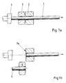
- the material 1 is drawn in in the direction of the arrow, pushed forward by two pairs of feed rollers 22 (FIG. 4 b) one behind the other and pushed against a stop 4.
- the material is mainly thin wire, as is usually used for cold forming.
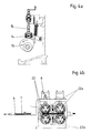
- the top feed rollers 22a according to FIG. 4b are raised, lowered and pressed against the wire 1 by means of pneumatic cylinders 6.
- the wire 1 is drawn in behind the feed rollers 22 first by a closed wire knife 2 and then by a likewise closed shaving knife 3 up to the stop 4.
- the shear knife 3 is displaced, for example in the direction of the arrow, transversely to the feed direction and thereby separates a wire section 5 shown in FIG. 1b from the wire 1.
- each feed roller 2 is driven individually in Fig. 4b.
- the only intermittent and unidirectional rotation of the feed rollers 22 is generated by the pendulum movement of a feed stroke adjusting lever 7 in conjunction with a freewheel 8 which is coupled to the adjusting lever 7 by a feed transmission rod 9.
- a gear transmission 11, 12 of the feed roller drive is connected to the freewheel 10.
- the gearwheels are connected to the feed rollers 22a and 22b via feed roller shafts 20, 24.
- the feed stroke adjustment lever 7 is in turn connected by a transmission rod 15 (see FIG. 4a), which rolls with a cam roller 14 on a feed control curve 13, to a main drive (not shown) for the forming press.
- An adjustment of the pull-in stroke can take place in that by means of a crank 16 attached to the pull-in adjustment lever 7 or a corresponding motor drive, an adjustment spindle 18 is rotated, which moves a sliding block 17 within a guide in the adjustment lever 7, whereby the stroke of the feed transmission rod is shortened or is extended.
- Scales 19 provided on the adjusting lever 7 and / or on the adjusting spindle 18 allow the stroke length to be read. Instead of the scales, electrical position indicators can also be provided.
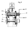
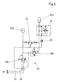
- a pair of drive rollers is connected to a schematically illustrated drive element, which is shown as a hydraulic motor 21 in the exemplary embodiment shown.
- This hydraulic motor exerts a torque counter to the drive torque on the feed roller shaft 20 and thus on the entire feed toothed gear 10, 11, 12.
- the direction of rotation of said upper feed roller 22a in FIG. 4b is clockwise as indicated by the rotation arrow, and the hydraulic motor 21 drives the same feed roller shaft 20 in the counterclockwise direction as shown in FIG. 5.
- An adjustment and control arrangement 23 (see FIG. 6) of the hydraulic motor 21 is used for adjustment and maintenance maintenance of this counteracting torque, which accounts for less than 50% of the feed roller drive torque.
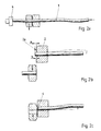
- the hydraulic motor 21, depending on the counter-torque setting selected via the setting and control arrangement 23, also acts as braking torque an essentially rebound-free bumping of the material against the stop 4. This prevents bending of the wire material (see FIG. 2a) before and after the shear tools 2, 3, and also prevents any burrs or compression of the wire material end face from the stop surface (see Fig. 2c).
- the counter torque preset by the hydraulic motor 21 further causes that in the standstill intervals of the feed roller drive, i.e. after the wire section 5 has been cut off, the wire 1 is drawn back in FIG. 1b, and so far until its end face is located behind the cutting edge 20 of the wire knife.
- the shaving knife 3 can return to its shearing position without the wire scraping along its cutting surface.
- the end face at "c" (FIG. 2c) of the wire material therefore always remains unchanged after separation, and the shear blade surface is not exposed to any risk of damage or even increased wear.
- the contact surface of the stop 4 and its adjusting device is protected in a wear-reducing manner by gently striking the wire end face.
- the pressure medium can easily be cooled via the hydraulic lines outside the feed area of the press, so that the generation of the counteracting torque is practically wear-free.
- An easy function monitoring of the hydraulic motor via the setting and control arrangement 23 can be carried out by pressure switches or the like. Known elements.
- the coupling of the feed drive shown in FIG. 2 via the mechanical cam mechanism to the main drive of the forming press represents a type of drive with high drive reliability and an extremely favorable energy balance.
- the described invention thus makes it possible to implement, with uncomplicated means, the simultaneous starting of all the feed rollers, the soft landing of the raw material at the stop, and the retraction of the material in the feed interval.
- this expression should include not only the material that can be pulled off a wire reel, but also the bar material that is usually processed on hot pressing.
Landscapes
- Engineering & Computer Science (AREA)
- Mechanical Engineering (AREA)
- Forging (AREA)
- Wire Processing (AREA)
- Shearing Machines (AREA)
- Paper (AREA)
Priority Applications (1)
| Application Number | Priority Date | Filing Date | Title |
|---|---|---|---|
| AT90810734T ATE97596T1 (de) | 1989-09-27 | 1990-09-25 | Verfahren und vorrichtung zum einziehen von draht in eine scherstation einer umformpresse. |
Applications Claiming Priority (2)
| Application Number | Priority Date | Filing Date | Title |
|---|---|---|---|
| CH3506/89 | 1989-09-27 | ||
| CH350689 | 1989-09-27 |
Publications (2)
| Publication Number | Publication Date |
|---|---|
| EP0420820A1 true EP0420820A1 (fr) | 1991-04-03 |
| EP0420820B1 EP0420820B1 (fr) | 1993-11-24 |
Family
ID=4257456
Family Applications (1)
| Application Number | Title | Priority Date | Filing Date |
|---|---|---|---|
| EP90810734A Expired - Lifetime EP0420820B1 (fr) | 1989-09-27 | 1990-09-25 | Procédé et dispositif pour enfiler du fil dans une station de coupe d'une presse de formage |
Country Status (5)
| Country | Link |
|---|---|
| US (1) | US5156073A (fr) |
| EP (1) | EP0420820B1 (fr) |
| JP (1) | JP2520192B2 (fr) |
| AT (1) | ATE97596T1 (fr) |
| DE (1) | DE59003596D1 (fr) |
Cited By (4)
| Publication number | Priority date | Publication date | Assignee | Title |
|---|---|---|---|---|
| EP1815928A4 (fr) * | 2004-11-26 | 2012-07-25 | Bridgestone Corp | Dispositif et procede de coupe |
| CN102728612A (zh) * | 2012-05-30 | 2012-10-17 | 上海新华锦焊接材料科技有限公司 | 自动锡丝轧机 |
| CN106955908A (zh) * | 2017-05-16 | 2017-07-18 | 北京京诚之星科技开发有限公司 | 一种紧凑式厚板翻压一体式生产设备 |
| CH712716A1 (de) * | 2016-07-19 | 2018-01-31 | Hatebur Umformmaschinen Ag | Verfahren und Vorrichtung zum Abscheren von Stangenmaterial. |
Families Citing this family (9)
| Publication number | Priority date | Publication date | Assignee | Title |
|---|---|---|---|---|
| JP3408899B2 (ja) * | 1995-08-18 | 2003-05-19 | 光信 飯野 | 中空管の自動切断装置における工作物の給排装置 |
| DE19837754A1 (de) * | 1998-08-20 | 2000-03-02 | Wafios Maschinen Wagner | Hochgeschwindigkeits-Schlagschere zum Abscheren von Stangen- und Drahtabschnitten |
| US6832535B1 (en) * | 2000-09-25 | 2004-12-21 | Rockford Manufacturing Group | Air ejection and compliant gage pin for rod cutting machines |
| TWI294800B (en) * | 2005-02-17 | 2008-03-21 | Hatebur Umformmaschinen Ag | Forming machine having a shearing device for shearing a bar |
| US8402870B1 (en) | 2008-11-13 | 2013-03-26 | Michael S. Marquette | Multi-function flying notching and shearing machine |
| CN107931704A (zh) * | 2017-11-16 | 2018-04-20 | 宁波市鄞州堃信工业产品设计有限公司 | 一种管道切割机的传动机构 |
| CN110434258B (zh) * | 2019-08-27 | 2020-03-31 | 东阳罗素电子科技有限公司 | 一种建筑使用的钢丝切割器 |
| CN112974691B (zh) * | 2021-04-28 | 2022-06-07 | 深圳中宝新材科技有限公司 | 一种用于银合金键合丝裁切用工装夹具及其工作方法 |
| CN115815465B (zh) * | 2023-02-15 | 2023-05-02 | 南通固邦数控机床有限公司 | 一种机械加工用的加强钢筋辅助矫直装置 |
Citations (7)
| Publication number | Priority date | Publication date | Assignee | Title |
|---|---|---|---|---|
| DE275787C (fr) * | ||||
| GB633704A (en) * | 1946-01-31 | 1949-12-19 | Nat Machinery Co | Improvements in or relating to a stock feeding device |
| DE1074537B (de) * | 1960-02-04 | Meyer, Roth & Pastor, Köln-Raderberg | Drahtabschneidevorrichtung | |
| GB973560A (en) * | 1962-02-28 | 1964-10-28 | Zd Y V I Plzen | Method of and apparatus for feeding material into ingot shears or slab shears |
| GB1024798A (en) * | 1964-03-03 | 1966-04-06 | Heinrich Georg | Arrangement for cutting intermittently moved material to length |
| DE2118652B2 (fr) * | 1971-04-17 | 1974-11-07 | Carl Ulrich Dr. 5600 Wuppertal Peddinghaus | |
| EP0196466A2 (fr) * | 1985-03-01 | 1986-10-08 | Sumitomo Metal Industries, Ltd. | Procédé et appareil d'alimentation en matériau d'une machine de forgeage à chaud |
Family Cites Families (5)
| Publication number | Priority date | Publication date | Assignee | Title |
|---|---|---|---|---|
| US1848835A (en) * | 1932-03-08 | Metal wobking machineby and method | ||
| US1969503A (en) * | 1930-07-31 | 1934-08-07 | Budd Wheel Co | Bar metering system |
| US3114282A (en) * | 1958-04-05 | 1963-12-17 | Reifenhauser K G | Apparatus for the transverse severance of continuously moving tubular structures |
| US3800645A (en) * | 1972-09-21 | 1974-04-02 | Fasteners Eng Inc | Hydraulically operated cropping apparatus |
| US4938907A (en) * | 1989-06-27 | 1990-07-03 | Motorola Inc. | Braided sleeve cutter and method |
-
1990
- 1990-09-25 DE DE90810734T patent/DE59003596D1/de not_active Expired - Fee Related
- 1990-09-25 AT AT90810734T patent/ATE97596T1/de active
- 1990-09-25 EP EP90810734A patent/EP0420820B1/fr not_active Expired - Lifetime
- 1990-09-26 US US07/588,147 patent/US5156073A/en not_active Expired - Fee Related
- 1990-09-27 JP JP2258803A patent/JP2520192B2/ja not_active Expired - Lifetime
Patent Citations (7)
| Publication number | Priority date | Publication date | Assignee | Title |
|---|---|---|---|---|
| DE275787C (fr) * | ||||
| DE1074537B (de) * | 1960-02-04 | Meyer, Roth & Pastor, Köln-Raderberg | Drahtabschneidevorrichtung | |
| GB633704A (en) * | 1946-01-31 | 1949-12-19 | Nat Machinery Co | Improvements in or relating to a stock feeding device |
| GB973560A (en) * | 1962-02-28 | 1964-10-28 | Zd Y V I Plzen | Method of and apparatus for feeding material into ingot shears or slab shears |
| GB1024798A (en) * | 1964-03-03 | 1966-04-06 | Heinrich Georg | Arrangement for cutting intermittently moved material to length |
| DE2118652B2 (fr) * | 1971-04-17 | 1974-11-07 | Carl Ulrich Dr. 5600 Wuppertal Peddinghaus | |
| EP0196466A2 (fr) * | 1985-03-01 | 1986-10-08 | Sumitomo Metal Industries, Ltd. | Procédé et appareil d'alimentation en matériau d'une machine de forgeage à chaud |
Cited By (7)
| Publication number | Priority date | Publication date | Assignee | Title |
|---|---|---|---|---|
| EP1815928A4 (fr) * | 2004-11-26 | 2012-07-25 | Bridgestone Corp | Dispositif et procede de coupe |
| CN102728612A (zh) * | 2012-05-30 | 2012-10-17 | 上海新华锦焊接材料科技有限公司 | 自动锡丝轧机 |
| CN102728612B (zh) * | 2012-05-30 | 2015-07-22 | 上海新华锦焊接材料科技有限公司 | 自动锡丝轧机 |
| CH712716A1 (de) * | 2016-07-19 | 2018-01-31 | Hatebur Umformmaschinen Ag | Verfahren und Vorrichtung zum Abscheren von Stangenmaterial. |
| US11040405B2 (en) | 2016-07-19 | 2021-06-22 | Hatebur Umformmaschinen Ag | Method and device for shearing rod material |
| CN106955908A (zh) * | 2017-05-16 | 2017-07-18 | 北京京诚之星科技开发有限公司 | 一种紧凑式厚板翻压一体式生产设备 |
| CN106955908B (zh) * | 2017-05-16 | 2019-01-25 | 北京京诚之星科技开发有限公司 | 一种紧凑式厚板翻压一体式生产设备 |
Also Published As
| Publication number | Publication date |
|---|---|
| ATE97596T1 (de) | 1993-12-15 |
| EP0420820B1 (fr) | 1993-11-24 |
| JP2520192B2 (ja) | 1996-07-31 |
| JPH03178715A (ja) | 1991-08-02 |
| DE59003596D1 (de) | 1994-01-05 |
| US5156073A (en) | 1992-10-20 |
Similar Documents
| Publication | Publication Date | Title |
|---|---|---|
| EP0420820B1 (fr) | Procédé et dispositif pour enfiler du fil dans une station de coupe d'une presse de formage | |
| DE2133144B2 (de) | Verfahren und Vorrichtung zum Ausfordern und Richten eines Stranges in einer Stranggiessanlage | |
| EP0400385A2 (fr) | Presse à refouler volante | |
| DE3806352A1 (de) | Vorrichtung zum auswerfen von werkstuecken aus matrizen in einer umformpresse | |
| EP3003702B1 (fr) | Procédé permettant de commander une presse à démultiplication variable de la transmission | |
| DE1527637C3 (de) | Vorrichtung zum Abbremsen des Antriebes und Ausrücken der Walzen in einem Walzwerk | |
| DE972615C (de) | Ziehpresse | |
| DE3239899C2 (de) | Vorrichtung an einer Stabstahlschere zum Abscheren von Abschnitten genauer Länge | |
| DE2131013A1 (de) | Presse,insbesondere Ziehpresse | |
| DE69016650T2 (de) | Regelungsanordnung und verfahren für das progressive brechen von zu behandelnden stücken. | |
| EP3487647B1 (fr) | Procede et dispositif pour cissailler le materiau d'une barre | |
| EP3700694A1 (fr) | Procédé pour couper un brin coulé ou une bande intermédiaire au moyen d'une cisaille | |
| DE1577246B2 (de) | Sicherungseinrichtung fuer arbeitsmaschinen | |
| DE1267945B (de) | Vorrichtung zum Einstellen und Nachstellen der Messer von Metallscheren, insbesondere von schweren maschinell angetriebenen Blechscheren | |
| DD158750A5 (de) | Schnellaufende schmiedemaschine | |
| DE2704517C3 (de) | Vorrichtung zur Steuerung sowohl der Verschiebung als auch der Kraftübertragung bei einer längs verschiebbaren Antriebsvorrichtung | |
| EP0501211B1 (fr) | Procédé pour actionner une presse à refouler | |
| DE1913807A1 (de) | Vorrichtung zur Mitnahme eines langen Gegenstandes | |
| DE3200255C2 (fr) | ||
| DE887591C (de) | Sicherheitsvorrichtung gegen UEberlastung von Antriebs- und Vorschubteilen an Werkzeugmaschinen | |
| DE3206681A1 (de) | Hydraulisch angetriebene schneidemaschine fuer papierbogen od. dgl. | |
| DE68918917T2 (de) | Stauchpresse mit horizontal gegenüberliegenden Stempeln. | |
| EP2483065A1 (fr) | Procédé pour déplacer une unité de façonnage d'une machine | |
| DE689301C (de) | Von unten nach oben schneidende Schere fuer Knueppel o. dgl. | |
| EP4302947A1 (fr) | Machine de coupe |
Legal Events
| Date | Code | Title | Description |
|---|---|---|---|
| PUAI | Public reference made under article 153(3) epc to a published international application that has entered the european phase |
Free format text: ORIGINAL CODE: 0009012 |
|
| AK | Designated contracting states |
Kind code of ref document: A1 Designated state(s): AT BE CH DE FR GB IT LI NL SE |
|
| 17P | Request for examination filed |
Effective date: 19910612 |
|
| 17Q | First examination report despatched |
Effective date: 19921130 |
|
| GRAA | (expected) grant |
Free format text: ORIGINAL CODE: 0009210 |
|
| AK | Designated contracting states |
Kind code of ref document: B1 Designated state(s): AT BE CH DE FR GB IT LI NL SE |
|
| REF | Corresponds to: |
Ref document number: 97596 Country of ref document: AT Date of ref document: 19931215 Kind code of ref document: T |
|
| ITF | It: translation for a ep patent filed | ||
| GBT | Gb: translation of ep patent filed (gb section 77(6)(a)/1977) |
Effective date: 19931208 |
|
| REF | Corresponds to: |
Ref document number: 59003596 Country of ref document: DE Date of ref document: 19940105 |
|
| ET | Fr: translation filed | ||
| PLBE | No opposition filed within time limit |
Free format text: ORIGINAL CODE: 0009261 |
|
| STAA | Information on the status of an ep patent application or granted ep patent |
Free format text: STATUS: NO OPPOSITION FILED WITHIN TIME LIMIT |
|
| 26N | No opposition filed | ||
| EAL | Se: european patent in force in sweden |
Ref document number: 90810734.5 |
|
| PGFP | Annual fee paid to national office [announced via postgrant information from national office to epo] |
Ref country code: SE Payment date: 19970715 Year of fee payment: 8 |
|
| PGFP | Annual fee paid to national office [announced via postgrant information from national office to epo] |
Ref country code: AT Payment date: 19970825 Year of fee payment: 8 |
|
| PG25 | Lapsed in a contracting state [announced via postgrant information from national office to epo] |
Ref country code: AT Free format text: LAPSE BECAUSE OF NON-PAYMENT OF DUE FEES Effective date: 19980925 |
|
| PG25 | Lapsed in a contracting state [announced via postgrant information from national office to epo] |
Ref country code: SE Free format text: LAPSE BECAUSE OF NON-PAYMENT OF DUE FEES Effective date: 19980926 |
|
| EUG | Se: european patent has lapsed |
Ref document number: 90810734.5 |
|
| REG | Reference to a national code |
Ref country code: GB Ref legal event code: IF02 |
|
| PGFP | Annual fee paid to national office [announced via postgrant information from national office to epo] |
Ref country code: FR Payment date: 20020827 Year of fee payment: 13 |
|
| PGFP | Annual fee paid to national office [announced via postgrant information from national office to epo] |
Ref country code: CH Payment date: 20020905 Year of fee payment: 13 |
|
| PGFP | Annual fee paid to national office [announced via postgrant information from national office to epo] |
Ref country code: BE Payment date: 20020913 Year of fee payment: 13 |
|
| PGFP | Annual fee paid to national office [announced via postgrant information from national office to epo] |
Ref country code: GB Payment date: 20020925 Year of fee payment: 13 |
|
| PGFP | Annual fee paid to national office [announced via postgrant information from national office to epo] |
Ref country code: NL Payment date: 20020930 Year of fee payment: 13 |
|
| PGFP | Annual fee paid to national office [announced via postgrant information from national office to epo] |
Ref country code: DE Payment date: 20021129 Year of fee payment: 13 |
|
| PG25 | Lapsed in a contracting state [announced via postgrant information from national office to epo] |
Ref country code: GB Free format text: LAPSE BECAUSE OF NON-PAYMENT OF DUE FEES Effective date: 20030925 |
|
| PG25 | Lapsed in a contracting state [announced via postgrant information from national office to epo] |
Ref country code: LI Free format text: LAPSE BECAUSE OF NON-PAYMENT OF DUE FEES Effective date: 20030930 Ref country code: CH Free format text: LAPSE BECAUSE OF NON-PAYMENT OF DUE FEES Effective date: 20030930 Ref country code: BE Free format text: LAPSE BECAUSE OF NON-PAYMENT OF DUE FEES Effective date: 20030930 |
|
| BERE | Be: lapsed |
Owner name: *HATEBUR UMFORMMASCHINEN A.G. Effective date: 20030930 |
|
| PG25 | Lapsed in a contracting state [announced via postgrant information from national office to epo] |
Ref country code: NL Free format text: LAPSE BECAUSE OF NON-PAYMENT OF DUE FEES Effective date: 20040401 Ref country code: DE Free format text: LAPSE BECAUSE OF NON-PAYMENT OF DUE FEES Effective date: 20040401 |
|
| GBPC | Gb: european patent ceased through non-payment of renewal fee |
Effective date: 20030925 |
|
| REG | Reference to a national code |
Ref country code: CH Ref legal event code: PL |
|
| PG25 | Lapsed in a contracting state [announced via postgrant information from national office to epo] |
Ref country code: FR Free format text: LAPSE BECAUSE OF NON-PAYMENT OF DUE FEES Effective date: 20040528 |
|
| NLV4 | Nl: lapsed or anulled due to non-payment of the annual fee |
Effective date: 20040401 |
|
| REG | Reference to a national code |
Ref country code: FR Ref legal event code: ST |
|
| PG25 | Lapsed in a contracting state [announced via postgrant information from national office to epo] |
Ref country code: IT Free format text: LAPSE BECAUSE OF NON-PAYMENT OF DUE FEES;WARNING: LAPSES OF ITALIAN PATENTS WITH EFFECTIVE DATE BEFORE 2007 MAY HAVE OCCURRED AT ANY TIME BEFORE 2007. THE CORRECT EFFECTIVE DATE MAY BE DIFFERENT FROM THE ONE RECORDED. Effective date: 20050925 |