EP0420838B1 - Appareil de traitement d'animaux tues en abattoir - Google Patents
Appareil de traitement d'animaux tues en abattoir Download PDFInfo
- Publication number
- EP0420838B1 EP0420838B1 EP88903474A EP88903474A EP0420838B1 EP 0420838 B1 EP0420838 B1 EP 0420838B1 EP 88903474 A EP88903474 A EP 88903474A EP 88903474 A EP88903474 A EP 88903474A EP 0420838 B1 EP0420838 B1 EP 0420838B1
- Authority
- EP
- European Patent Office
- Prior art keywords
- solution
- valve
- flow
- header
- conduit
- Prior art date
- Legal status (The legal status is an assumption and is not a legal conclusion. Google has not performed a legal analysis and makes no representation as to the accuracy of the status listed.)
- Expired - Lifetime
Links
- 241001465754 Metazoa Species 0.000 title claims abstract description 19
- 239000000243 solution Substances 0.000 claims abstract description 47
- 238000002347 injection Methods 0.000 claims abstract description 14
- 239000007924 injection Substances 0.000 claims abstract description 14
- 230000003134 recirculating effect Effects 0.000 claims abstract 3
- 238000001816 cooling Methods 0.000 claims description 5
- 238000012544 monitoring process Methods 0.000 claims description 2
- 229910001220 stainless steel Inorganic materials 0.000 description 6
- 239000010935 stainless steel Substances 0.000 description 6
- 210000002414 leg Anatomy 0.000 description 5
- 238000000034 method Methods 0.000 description 3
- XLYOFNOQVPJJNP-UHFFFAOYSA-N water Substances O XLYOFNOQVPJJNP-UHFFFAOYSA-N 0.000 description 3
- CIWBSHSKHKDKBQ-JLAZNSOCSA-N Ascorbic acid Chemical compound OC[C@H](O)[C@H]1OC(=O)C(O)=C1O CIWBSHSKHKDKBQ-JLAZNSOCSA-N 0.000 description 2
- WCUXLLCKKVVCTQ-UHFFFAOYSA-M Potassium chloride Chemical compound [Cl-].[K+] WCUXLLCKKVVCTQ-UHFFFAOYSA-M 0.000 description 2
- 239000004365 Protease Substances 0.000 description 2
- FAPWRFPIFSIZLT-UHFFFAOYSA-M Sodium chloride Chemical compound [Na+].[Cl-] FAPWRFPIFSIZLT-UHFFFAOYSA-M 0.000 description 2
- 235000013305 food Nutrition 0.000 description 2
- 210000004731 jugular vein Anatomy 0.000 description 2
- 239000007788 liquid Substances 0.000 description 2
- 239000003507 refrigerant Substances 0.000 description 2
- 238000003860 storage Methods 0.000 description 2
- 125000000391 vinyl group Chemical group [H]C([*])=C([H])[H] 0.000 description 2
- 229920002554 vinyl polymer Polymers 0.000 description 2
- OWEGMIWEEQEYGQ-UHFFFAOYSA-N 100676-05-9 Natural products OC1C(O)C(O)C(CO)OC1OCC1C(O)C(O)C(O)C(OC2C(OC(O)C(O)C2O)CO)O1 OWEGMIWEEQEYGQ-UHFFFAOYSA-N 0.000 description 1
- CHHHXKFHOYLYRE-UHFFFAOYSA-M 2,4-Hexadienoic acid, potassium salt (1:1), (2E,4E)- Chemical compound [K+].CC=CC=CC([O-])=O CHHHXKFHOYLYRE-UHFFFAOYSA-M 0.000 description 1
- 108010004032 Bromelains Proteins 0.000 description 1
- UXVMQQNJUSDDNG-UHFFFAOYSA-L Calcium chloride Chemical compound [Cl-].[Cl-].[Ca+2] UXVMQQNJUSDDNG-UHFFFAOYSA-L 0.000 description 1
- 241000282994 Cervidae Species 0.000 description 1
- RYGMFSIKBFXOCR-UHFFFAOYSA-N Copper Chemical compound [Cu] RYGMFSIKBFXOCR-UHFFFAOYSA-N 0.000 description 1
- 241000283086 Equidae Species 0.000 description 1
- 108090000270 Ficain Proteins 0.000 description 1
- WQZGKKKJIJFFOK-GASJEMHNSA-N Glucose Natural products OC[C@H]1OC(O)[C@H](O)[C@@H](O)[C@@H]1O WQZGKKKJIJFFOK-GASJEMHNSA-N 0.000 description 1
- GUBGYTABKSRVRQ-PICCSMPSSA-N Maltose Natural products O[C@@H]1[C@@H](O)[C@H](O)[C@@H](CO)O[C@@H]1O[C@@H]1[C@@H](CO)OC(O)[C@H](O)[C@H]1O GUBGYTABKSRVRQ-PICCSMPSSA-N 0.000 description 1
- 102000014171 Milk Proteins Human genes 0.000 description 1
- 108010011756 Milk Proteins Proteins 0.000 description 1
- 108090000526 Papain Proteins 0.000 description 1
- 241000282887 Suidae Species 0.000 description 1
- 239000004809 Teflon Substances 0.000 description 1
- 229920006362 Teflon® Polymers 0.000 description 1
- 239000007864 aqueous solution Substances 0.000 description 1
- 235000010323 ascorbic acid Nutrition 0.000 description 1
- 229960005070 ascorbic acid Drugs 0.000 description 1
- 239000011668 ascorbic acid Substances 0.000 description 1
- 235000015278 beef Nutrition 0.000 description 1
- CJPQIRJHIZUAQP-MRXNPFEDSA-N benalaxyl-M Chemical compound CC=1C=CC=C(C)C=1N([C@H](C)C(=O)OC)C(=O)CC1=CC=CC=C1 CJPQIRJHIZUAQP-MRXNPFEDSA-N 0.000 description 1
- WQZGKKKJIJFFOK-VFUOTHLCSA-N beta-D-glucose Chemical compound OC[C@H]1O[C@@H](O)[C@H](O)[C@@H](O)[C@@H]1O WQZGKKKJIJFFOK-VFUOTHLCSA-N 0.000 description 1
- GUBGYTABKSRVRQ-QUYVBRFLSA-N beta-maltose Chemical compound OC[C@H]1O[C@H](O[C@H]2[C@H](O)[C@@H](O)[C@H](O)O[C@@H]2CO)[C@H](O)[C@@H](O)[C@@H]1O GUBGYTABKSRVRQ-QUYVBRFLSA-N 0.000 description 1
- 239000008280 blood Substances 0.000 description 1
- 210000004369 blood Anatomy 0.000 description 1
- 239000001110 calcium chloride Substances 0.000 description 1
- 229910001628 calcium chloride Inorganic materials 0.000 description 1
- 210000000748 cardiovascular system Anatomy 0.000 description 1
- 229910052802 copper Inorganic materials 0.000 description 1
- 239000010949 copper Substances 0.000 description 1
- 230000008878 coupling Effects 0.000 description 1
- 238000010168 coupling process Methods 0.000 description 1
- 238000005859 coupling reaction Methods 0.000 description 1
- 238000011161 development Methods 0.000 description 1
- 230000018109 developmental process Effects 0.000 description 1
- 239000008121 dextrose Substances 0.000 description 1
- 238000009826 distribution Methods 0.000 description 1
- 238000004134 energy conservation Methods 0.000 description 1
- 235000019836 ficin Nutrition 0.000 description 1
- POTUGHMKJGOKRI-UHFFFAOYSA-N ficin Chemical compound FI=CI=N POTUGHMKJGOKRI-UHFFFAOYSA-N 0.000 description 1
- 239000012530 fluid Substances 0.000 description 1
- 230000006872 improvement Effects 0.000 description 1
- 238000009413 insulation Methods 0.000 description 1
- 210000000629 knee joint Anatomy 0.000 description 1
- 210000003141 lower extremity Anatomy 0.000 description 1
- 230000007257 malfunction Effects 0.000 description 1
- 238000004519 manufacturing process Methods 0.000 description 1
- 235000013372 meat Nutrition 0.000 description 1
- 235000021239 milk protein Nutrition 0.000 description 1
- 239000000203 mixture Substances 0.000 description 1
- 235000019834 papain Nutrition 0.000 description 1
- 229940055729 papain Drugs 0.000 description 1
- 229920003023 plastic Polymers 0.000 description 1
- 239000004033 plastic Substances 0.000 description 1
- 239000001103 potassium chloride Substances 0.000 description 1
- 235000011164 potassium chloride Nutrition 0.000 description 1
- 235000010241 potassium sorbate Nutrition 0.000 description 1
- 229940069338 potassium sorbate Drugs 0.000 description 1
- 239000004302 potassium sorbate Substances 0.000 description 1
- 244000144977 poultry Species 0.000 description 1
- 230000008569 process Effects 0.000 description 1
- 230000009467 reduction Effects 0.000 description 1
- 230000004044 response Effects 0.000 description 1
- 229910052710 silicon Inorganic materials 0.000 description 1
- 239000010703 silicon Substances 0.000 description 1
- 239000011780 sodium chloride Substances 0.000 description 1
- 239000001509 sodium citrate Substances 0.000 description 1
- NLJMYIDDQXHKNR-UHFFFAOYSA-K sodium citrate Chemical compound O.O.[Na+].[Na+].[Na+].[O-]C(=O)CC(O)(CC([O-])=O)C([O-])=O NLJMYIDDQXHKNR-UHFFFAOYSA-K 0.000 description 1
- 235000011083 sodium citrates Nutrition 0.000 description 1
- FQENQNTWSFEDLI-UHFFFAOYSA-J sodium diphosphate Chemical compound [Na+].[Na+].[Na+].[Na+].[O-]P([O-])(=O)OP([O-])([O-])=O FQENQNTWSFEDLI-UHFFFAOYSA-J 0.000 description 1
- 235000019832 sodium triphosphate Nutrition 0.000 description 1
- 235000019818 tetrasodium diphosphate Nutrition 0.000 description 1
- 238000011144 upstream manufacturing Methods 0.000 description 1
Images
Classifications
-
- A—HUMAN NECESSITIES
- A22—BUTCHERING; MEAT TREATMENT; PROCESSING POULTRY OR FISH
- A22B—SLAUGHTERING
- A22B5/00—Accessories for use during or after slaughtering
-
- A—HUMAN NECESSITIES
- A23—FOODS OR FOODSTUFFS; TREATMENT THEREOF, NOT COVERED BY OTHER CLASSES
- A23B—PRESERVATION OF FOODS, FOODSTUFFS OR NON-ALCOHOLIC BEVERAGES; CHEMICAL RIPENING OF FRUIT OR VEGETABLES
- A23B4/00—Preservation of meat, sausages, fish or fish products
- A23B4/26—Apparatus for preserving using liquids ; Processes therefor
- A23B4/28—Apparatus for preserving using liquids ; Processes therefor by injection of liquids
Definitions
- the subject invention is related to and is an improvement over US-A-4,053,963 and US-A-4,411,047.
- that prior art relates to meat treatment by injection of various liquid compositions and to apparatus for accomplishing same.
- the subject invention is specifically concerned with improved apparatus for use in the treatment of slaughtered animals by injecting treatment solution into the animal's circulatory system.
- the apparatus is useful in the treatment of beef, horses, hogs, poultry, deer, buffulo and the like.
- the apparatus may be portable or permanently located.
- this invention is capable of using any of a variaty of treatment solutions described in the prior art, especially aqueous solutions such as those referred to in US-A-4,053,963.
- aqueous solutions such as those referred to in US-A-4,053,963.
- water soluble polysacchride gum and/or calcium chloride, sodium chloride and potassium chloride may be included.
- the procedure for using the apparatus of the invention begins with the stunning of a steer, for example, following which it is hung by its hind leg or hind legs, usually on an overhead conveyer or the like.
- the jugular vein is then opened at the neck to bleed the animal.
- the incision is made in the heart.
- the animal may then be laid on a work surface with its legs extending upwardly or it may be kept hanging.
- all four leg vessels are severed, or all four legs are severed at the knee joints.
- An injector nozzle with a self-piercing tip is then inserted into the jugular at a location proximate to the earlier incision therein but closer to the heart.
- the injector nozzle being attached to a dispensing conduit of the apparatus, allows treatment solution to be pumped from the apparatus, through the nozzle and into the animal's circulatory system.
- the solution after forcing out residual blood, eventually exists from the severed leg vessels and from the first incision in the jugular vein.
- injection solution be delivered into the animal's cardiovascular system at a consistent pressure which is not so low as to lead to incomplete distribution throughout the animal or so high as to rupture vessels.
- US-A-4,411,047 discloses an apparatus for injection of the treatment solution into slaughtered animals including a container for holding the treatment solution, a manifold chamber and a conduit for recirculation of the treatment solution from the manifold chamber to the container.
- a centrifugal pump for creating a constant liquid pressure and an adjustable valve arranged downstream of the manifold chamber.
- the improved apparatus of this invention provides for a consistent, controlled pressure.
- An important feature of the apparatus comprises the use of an automatic control valve with a control system for control of downstream pressure to steady value. This is accomplished by locating the downstream pressure sensor of the value's control system in a critical location, to be described more fully below which provides substantially constant pressure values in single or multiple dispensing lines.
- the apparatus also provides for cooling of the treatment solution. This "rapid chills" the animal and enhances the butchering and deboning of the carcass.
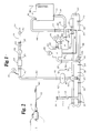
- the solution handling section of the apparatus is shown in schematic for simplicity of understanding. It includes a stainless steel storage container means or tank 12 for holding treatment solution.
- Tank 12 may be of varying size and shape.
- a preferred tank is one of about 653 liters (170 gallon) volume, 16 gauge about 97 cm x 89 cm x 137 cm (38 inches x 35 inches and 54 inches) having a piano-hinged top (not shown) as provided by Process Equipment Corporation of Belding, MI 48809.
- a first conduit means preferably in the form of a 1-1/2 inch conduit arrangement 14 and which may include stainless steel elbows and vinyl food handling tubing as necessary, for carrying treatment solution from tank 12 to a pump 16 or other suitable means for creating a flow of solution in the apparatus.
- a manual valve 18 may be included in this section of the conduit line. It may, for example be a Cooper Manufacturing ball valve Model #4151 SE 316 3-PC.
- a Thomsen clamp 20 may be used to attach conduit 14 to pump 16.
- a typical clamp for this purpose is a T-13, double screw, wing nut clamp which includes a silicon or Teflon gasket. Such clamps may be used throughout the apparatus as indicated by legend 20 throughout.
- conduit 14 may be reduced in diameter from 38,1 mm to 31,8 mm (1-1/2 inches to 1-1/4 inches at some point between coupling 20 and valve 18 to adapt conduit size to standard intake line size of the pump.
- Pump 16 in turn conducts treatment solution to automatic valve 22 via a second conduit means in the form of a conduit line 24 which is 1 inch in diameter as is the remaining conduit line associated with the apparatus up to the injection nozzle.
- this reduction in size is to accommodate standard parts, the pump output being 1 inch in diameter.
- Pump 16 is preferably an electrically operated pump, more preferably of the centrifugal type such as the FST-3000, Model 35 Stainless Steel Centrifugal Pump (close coupled) as provided by the Bell & Gossett Fluid Handling Division of ITT Corporation.
- a pressure gauge 26 may be included in line 24 for monitoring purposes. This valve may typically be of the stainless steel pressure valve type #WI 233.50 provided by WIKA of Hauppauge, New York with a 2-1/2 inch dial.
- Automatic control valve 22 is of the type which is designed to control downstream pressure to a steady value regardless of changing flow rate and/or varying inlet pressure.
- One such valve capable of accomplishing this is the type available from the Cla-Val Co. of Newport Beach, CA, as Model 90-01 Series (90G-01 ABSKG). It is a pressure reducing valve which consists of a main valve and a pilot control system including a pressure reducing valve (not shown) (model CRD) and a pressure sensing line or feedback conduit 30.
- the location of the open end of pressure sensing line 30 is critical to the operation of the apparatus.
- the end of line 30 can only be located at the "T" intersection where recirculation line 44 meets header line 36, as shown is an example of such an arrangment.
- Treatment solution is conducted from pump 16 through valve 22 to a header means generally indicated at 32 via a third conduit means in the form of conduit line 34.
- Header 32 is preferably comprised of paired conduit means 36 and 38, preferably, having a common inlet 40 and having a common outlet 42, between which the flow of treatment solution exiting from conduit 34 branches into two directions in header 32 to meet at common outlet 42. One branch or more than two branches may also be used.
- the flow of treatment solution meeting at common outlet 42 recirculates to storage container 12 via fourth conduit means in the form of a recirculation or conduit line 44 extending to the inlet 45 of container 12.
- Line 44 may contain a manual valve 46 which may be a Worcester ball valve product #WOC 5866R-SE.
- Manual valves 18 and 46 are placed in lines 14 and 44, respectively to accommodate replacement of tank 12. In operation, multiple tanks will be used. When one tank empties, valves 18 and 46 are closed and the apparatus is disconnected and reconnected to a fresh tank. The valves are opened and processing is continued. The empty tank may then be recharged with treatment solution for subsequent use.
- locating pressure sensor 30 for automatic valve 22 proximate the common outlet 42 of header 32, where the branched flow of solution meets, enables the valve to maintain the pressure in the header means and in all dispensing conduit means attached thereto, such as the means generally designated 60, at a steady value whether there is only one dispensing conduit or a plurality of them in use and attached to header means.
- additional dispensing conduit lines (not shown) will be included as at 48 and 50. Most preferably, four such lines will be included in the apparatus although only one is shown for simplicity of description.
- a drain line 52 with valve 54 and cap 56 may be included in header means 32.
- a drain 16a (normally closed) may also be included in the bottom of pump 16.
- conduit means 60 of which only one is shown, it is connected into header means 32 (36).
- Flow into conduit means 60 may be controlled by means of a valve 58 which is preferably of the same type as valve 54 in drain line 52, i.e., a manual butterfly valve.
- Conduit line 60 also includes a normally closed electrically operated valve 62 which is computer controlled as described further herein-below.
- Valve 62 may for example be a stainless steel electric ball valve of the type manufactured by James-bury of Worcester MA, Model A, Type 1"21-3600TT3 which is solenoid operated.
- Conduit means 60 may also include a pressure valve 26, a flow meter 64, a manual valve 66, a check valve 68 and a manual ball valve 70 to which an injection nozzle 72 is connected (best seen in detail in Figure 2).
- valve 66 is initially adjusted to a predetermined flow rate which is read on flowmeter 64 at which time the overall system is considered adjusted. Valve 66 is then left set more or less permanently.
- Flow meter 64 may be of the turbine type supplied by Halliburton Services, Special Products Division, Duncan Oklahoma as part #458.8001. Valve 66 may be of the same type described at 46 hereinabove in line 44.
- Valve 70 may be of the stainless steel ball type manufactured by Crane Ordway Corporatiron under the trademark CAPRI and identified as part #2000 CWP CF 8M.
- the section 74 of dispensing conduit means 46 will preferably consist of a convenient length of vinyl food handling tubing such as that available from Mayon Plastics of Hopkins, Minnesota 55343.
- a clamp arrangement (not shown) may be attached to the nozzle or upstream of it to hold the nozzle in position in the animal and force the operator for other duties. Any suitable clamp eg., an allegator clamp or the like, may be used for this purpose.
- FIG. 2 a detailed showing of the hollow injection nozzle 72 is provided. It includes a self-piercing tip 90 and is threaded at 92 to be fitted into valve 70. Nozzle 72 functions as a conduit for the treatment solution.
- the apparatus will also preferably include a solution cooling arrangement such as means 80 in container 12 for cooling the solution therein.
- a solution cooling arrangement such as means 80 in container 12 for cooling the solution therein.
- the arrangement shown in Figure 1 is schematic and 80 is intended to indicate a cooling coil and associated operational means such as condenser and refrigerant, as are well known. Any arrangement may be used.
- One such arrangement may include (not shown) a copper coil wrapped around tank 12 on the outside and bottom with insulation covering the coil similar to the hot water heater jacket used for energy conservation.
- a condenser may be connected to the coil and the system then charged with a refrigerant such as R-22. Such an arrangement will adequately cool the treatment solution.
- the apparatus is normally operated by two people.
- One person handles the injection nozzle which has been pre-set as described above with all valves "open” except for electrical valve 62.
- This person inserts the nozzle into the animal and signals a second person at a computer who is responsible for entering data appropriate to the animal to be treated.
Landscapes
- Life Sciences & Earth Sciences (AREA)
- Engineering & Computer Science (AREA)
- Food Science & Technology (AREA)
- Polymers & Plastics (AREA)
- Zoology (AREA)
- Chemical & Material Sciences (AREA)
- Wood Science & Technology (AREA)
- Meat, Egg Or Seafood Products (AREA)
- Medicines Containing Material From Animals Or Micro-Organisms (AREA)
- Automatic Analysis And Handling Materials Therefor (AREA)
- Pipeline Systems (AREA)
- Organic Low-Molecular-Weight Compounds And Preparation Thereof (AREA)
- Processing Of Meat And Fish (AREA)
- Flow Control (AREA)
- Management, Administration, Business Operations System, And Electronic Commerce (AREA)
Claims (12)
- Appareil d'injection d'une solution de traitement dans des animaux abattus comprenant :
un récipient (12) servant à contenir une quantité de solution de traitement ;
un moyen (14) d'établissement d'un courant de solution à partir de la source de récipient ;
une vanne de réglage automatique (22) pour recevoir le courant de solution, cette vanne incluant un moyen de réglage pour régler la pression en aval du courant de solution ;
un collecteur (32) pour recevoir un courant de solution venant de la vanne de réglage (22) ;
un conduit (44) reliant le collecteur (32) au récipient (12) pour recycler la solution vers celui-ci ;
un capteur de pression placé près de la zone (42) de raccordement du collecteur (32) et du conduit (44) afin d'y capter la pression ;
une ligne de réglage (30) reliant le capteur de pression au réglage de la vanne automatique (22), grâce à quoi la pression en aval de la vanne de réglage (22) est réglée à une valeur constante, et
au moins un conduit de distribution (60) relié au collecteur (32) pour recevoir de celui-ci une solution sous une pression contrôlée et pour l'injecter dans un animal abattu ;
dans lequel le collecteur (32) comprend un conduit dédoublé (36, 38) pour établir à travers celui-ci un courant de solution, comportant une dérivation ;
le conduit (44) qui se raccorde au collecteur (32) se raccorde aux parties situées en aval du conduit dédoublé, les courants qui les traversent étant réunis pour être recyclés vers le récipient (12),
et le capteur de pression est placé près de la zone de raccordement (42) et du point auquel, les courants traversant les conduits dédoubles se réunissent au voisinage de la liaison à la ligne de recyclage. - Appareil selon la revendication 1, comprenant une pompe (16) dont l'admission est. reliée à une sortie du récipient (12) et dont le refoulement est relié à l'entrée de la vanne de réglage automatique (22).
- Appareil selon l'une quelconque des revendications précédentes, incluant un moyen de synchronisation servant à régler la longueur du temps d'écoulement à travers le conduit de distribution (60), grâce à quoi la pression réglée et le temps réalisent la distribution de quantités contrôlées de solution de traitement.
- Appareil selon l'une quelconque des revendications précédentes, dans lequel le conduit de distribution (60) se termine dans une buse d'injection (72) de solution pour injecter la solution de traitement dans un animal abattu.
- Appareil selon l'une quelconque des revendications précédentes, incluant une vanne (62) pour régler le courant de solution venant du collecteur (32) et traversant le conduit (60) distributeur et le moyen d'injection (72).
- Appareil selon la revendication 5, dans lequel la vanne (62) est commandée électriquement.
- Appareil selon la revendication 6, incluant un ordinateur pour surveiller la commande électrique de la vanne (62).
- Appareil selon l'une quelconque des revendications précédentes, incluant une série de conduits de distribution (60) et de moyens d'injection (72) séparés, reliés au collecteur (32), et des vannes correspondantes séparées (62) réglant le courant qui les traverse.
- Appareil selon la revendication 8, dans lequel chacune des vannes séparées est réglée électriquement.
- Appareil selon la revendication 9, incluant un ordinateur pour maintenir un réglage des vannes séparées.
- Appareil selon la revendication 4, dans lequel la buse d'injection (72) se termine en une pointe à perçage autonome.
- Appareil selon l'une quelconque des revendications précédentes, incluant un moyen (80) associé à la solution pour la refroidir au-dessous de la température ambiante.
Priority Applications (1)
| Application Number | Priority Date | Filing Date | Title |
|---|---|---|---|
| EP92112782A EP0525696B1 (fr) | 1987-02-11 | 1988-02-02 | Appareil de traitement d'animaux abattus |
Applications Claiming Priority (3)
| Application Number | Priority Date | Filing Date | Title |
|---|---|---|---|
| US07/013,580 US5007336A (en) | 1987-02-11 | 1987-02-11 | Apparatus for treating slaughtered animals |
| US13580 | 1987-02-11 | ||
| PCT/US1988/000301 WO1988006003A1 (fr) | 1987-02-11 | 1988-02-02 | Appareil de traitement d'animaux tues en abattoir |
Related Child Applications (2)
| Application Number | Title | Priority Date | Filing Date |
|---|---|---|---|
| EP92112782A Division EP0525696B1 (fr) | 1987-02-11 | 1988-02-02 | Appareil de traitement d'animaux abattus |
| EP92112782A Division-Into EP0525696B1 (fr) | 1987-02-11 | 1988-02-02 | Appareil de traitement d'animaux abattus |
Publications (3)
| Publication Number | Publication Date |
|---|---|
| EP0420838A1 EP0420838A1 (fr) | 1991-04-10 |
| EP0420838A4 EP0420838A4 (en) | 1991-12-18 |
| EP0420838B1 true EP0420838B1 (fr) | 1994-06-08 |
Family
ID=21760676
Family Applications (2)
| Application Number | Title | Priority Date | Filing Date |
|---|---|---|---|
| EP88903474A Expired - Lifetime EP0420838B1 (fr) | 1987-02-11 | 1988-02-02 | Appareil de traitement d'animaux tues en abattoir |
| EP92112782A Expired - Lifetime EP0525696B1 (fr) | 1987-02-11 | 1988-02-02 | Appareil de traitement d'animaux abattus |
Family Applications After (1)
| Application Number | Title | Priority Date | Filing Date |
|---|---|---|---|
| EP92112782A Expired - Lifetime EP0525696B1 (fr) | 1987-02-11 | 1988-02-02 | Appareil de traitement d'animaux abattus |
Country Status (8)
| Country | Link |
|---|---|
| US (1) | US5007336A (fr) |
| EP (2) | EP0420838B1 (fr) |
| CN (2) | CN1027616C (fr) |
| AT (2) | ATE106671T1 (fr) |
| AU (1) | AU1572988A (fr) |
| CA (1) | CA1308468C (fr) |
| DE (2) | DE3850123T2 (fr) |
| WO (1) | WO1988006003A1 (fr) |
Families Citing this family (27)
| Publication number | Priority date | Publication date | Assignee | Title |
|---|---|---|---|---|
| GB2246501B (en) * | 1990-07-30 | 1994-06-01 | British Beef Co Ltd | Method of pre-tenderising meat |
| US5142971A (en) * | 1990-09-17 | 1992-09-01 | Knud Simonsen Industries Limited | Apparatus for injecting suspended meat solids into meats |
| US5464638A (en) * | 1991-08-26 | 1995-11-07 | Kakolewski; Jan W. | Perfusion aided meat processing |
| DE19616158C1 (de) * | 1996-04-23 | 1997-05-28 | U T G Ges Fuer Umwelttechnik G | Verfahren und Vorrichtung zur Beseitigung von insbesondere mit dem BSE-Erreger infizierten Tieren |
| US5761992A (en) * | 1997-03-12 | 1998-06-09 | Gallo; Charles V. | Portable animal storage unit |
| US6014926A (en) * | 1997-05-13 | 2000-01-18 | Prima Meat Packers, Ltd. | Injection into meat and pickle injector for use therein |
| US5931730A (en) * | 1997-06-06 | 1999-08-03 | Meat Processing Service Corporation | Secured sanitary catheter |
| US5964656A (en) * | 1998-05-19 | 1999-10-12 | Meat Processing Service Corp. Inc. | Radio frequency identification device and method of use |
| US6608561B2 (en) | 1998-05-19 | 2003-08-19 | Meat Processing Service Corp., Inc. | Method for making a radio frequency identification device |
| AU2001247989B2 (en) * | 1998-05-19 | 2004-06-03 | Meat Processing Service Corp. Inc. | Sanitary rinsing of an animal |
| US6196912B1 (en) | 1998-05-19 | 2001-03-06 | Meat Processing Service Corporation | Machine readable tag |
| NZ515385A (en) | 1999-04-30 | 2003-11-28 | Excel Corp | Method for processing an animal carcass and apparatus for providing electrical stimulation |
| US6658990B1 (en) * | 2000-11-27 | 2003-12-09 | Mepsco, Inc. | Bushing construction for a fluid injection machine in a food processing system |
| DE10201245B4 (de) * | 2002-01-11 | 2004-05-19 | Bundesdruckerei Gmbh | Verfahren zur Validierung von Schlachtprodukten |
| NL1024926C2 (nl) * | 2003-12-02 | 2005-06-06 | Townsend Engineering B V | Inrichting en werkwijze voor het met vloeistof bewerken van voedingsmiddelen. |
| ZA200701728B (en) * | 2004-07-28 | 2008-07-30 | Mpsc Inc | Method and apparatus for processing animals |
| US7606394B2 (en) * | 2006-04-03 | 2009-10-20 | Jbs Swift & Company | Methods and systems for administering a drug program related to livestock |
| US7613330B2 (en) * | 2006-04-03 | 2009-11-03 | Jbs Swift & Company | Methods and systems for tracking and managing livestock through the production process |
| US9159126B2 (en) | 2006-04-03 | 2015-10-13 | Jbs Usa, Llc | System and method for analyzing and processing food product |
| US20070282281A1 (en) * | 2006-05-19 | 2007-12-06 | Ide J W | Piercing tip |
| US7892076B2 (en) * | 2006-05-22 | 2011-02-22 | Swift & Company | Multibar apparatus and method for electrically stimulating a carcass |
| US20090249964A1 (en) * | 2006-07-11 | 2009-10-08 | Arni Bergmann Petursson | apparatus for injecting liquid into food objects |
| US7666074B2 (en) * | 2006-08-31 | 2010-02-23 | Mpsc, Inc. | Meat processing |
| DE202009009487U1 (de) * | 2009-07-11 | 2010-11-25 | Schröder Maschinenbau KG | Vorrichtung zur dosierten Injektion von Flüssigkeiten in Lebensmittelprodukte |
| CA2778248A1 (fr) * | 2009-10-30 | 2011-05-05 | Cargill, Incorporated | Procede de decollement d'un muscle et produits de viande bovine obtenus avec le procede |
| CA3032966C (fr) | 2016-08-03 | 2020-09-08 | Mpsc Australia, Pty., Ltd | Application de solution de rincage a haute vitesse |
| US10021885B2 (en) * | 2016-09-02 | 2018-07-17 | Mpsc, Inc. | Meat processing |
Family Cites Families (8)
| Publication number | Priority date | Publication date | Assignee | Title |
|---|---|---|---|---|
| CA573378A (fr) * | 1959-03-31 | Canada Packers Limited | Composition de phosphate de trisodium et methode pour preparer de la viande boucanee | |
| US2863777A (en) * | 1955-04-07 | 1958-12-09 | Vasco Ind Corp | Meat color preserving composition |
| GB802126A (en) * | 1955-04-07 | 1958-10-01 | Chemische Ind Paul Schoemaker | Improvements in or relating to the treatment of meat and meat products |
| US2812261A (en) * | 1956-04-12 | 1957-11-05 | Meat Industry Suppliers Inc | Composition and method for inhibiting color changes of cured meat products |
| US4053963A (en) * | 1975-12-29 | 1977-10-18 | Matheu Guillermo R | Portable apparatus for use in the treatment of slaughtered animals |
| US4411047A (en) * | 1979-02-21 | 1983-10-25 | Baxter Travenol Laboratories, Inc. | Liquid delivery system |
| US4275480A (en) * | 1979-02-21 | 1981-06-30 | Baxter Travenol Laboratories, Inc. | Electronic injection metering and monitoring system |
| ES8507324A1 (es) * | 1984-05-07 | 1985-09-01 | Metalquimia Sa | Maquina inyectora de masas carnicas de agujas retractiles, perfeccionada. |
-
1987
- 1987-02-11 US US07/013,580 patent/US5007336A/en not_active Expired - Lifetime
-
1988
- 1988-02-02 AT AT88903474T patent/ATE106671T1/de not_active IP Right Cessation
- 1988-02-02 DE DE3850123T patent/DE3850123T2/de not_active Expired - Lifetime
- 1988-02-02 EP EP88903474A patent/EP0420838B1/fr not_active Expired - Lifetime
- 1988-02-02 AT AT92112782T patent/ATE139882T1/de not_active IP Right Cessation
- 1988-02-02 WO PCT/US1988/000301 patent/WO1988006003A1/fr not_active Ceased
- 1988-02-02 EP EP92112782A patent/EP0525696B1/fr not_active Expired - Lifetime
- 1988-02-02 DE DE3855401T patent/DE3855401T2/de not_active Expired - Lifetime
- 1988-02-02 AU AU15729/88A patent/AU1572988A/en not_active Abandoned
- 1988-02-10 CA CA000558612A patent/CA1308468C/fr not_active Expired - Lifetime
- 1988-02-11 CN CN88101191A patent/CN1027616C/zh not_active Expired - Fee Related
-
1994
- 1994-07-17 CN CN94108589A patent/CN1041593C/zh not_active Expired - Fee Related
Also Published As
| Publication number | Publication date |
|---|---|
| ATE106671T1 (de) | 1994-06-15 |
| EP0525696A3 (en) | 1993-03-31 |
| EP0525696B1 (fr) | 1996-07-03 |
| CA1308468C (fr) | 1992-10-06 |
| EP0420838A1 (fr) | 1991-04-10 |
| DE3850123T2 (de) | 1995-02-16 |
| EP0525696A2 (fr) | 1993-02-03 |
| WO1988006003A1 (fr) | 1988-08-25 |
| CN1041593C (zh) | 1999-01-13 |
| DE3855401D1 (de) | 1996-08-08 |
| EP0420838A4 (en) | 1991-12-18 |
| AU1572988A (en) | 1988-09-14 |
| ATE139882T1 (de) | 1996-07-15 |
| DE3855401T2 (de) | 1997-02-20 |
| US5007336A (en) | 1991-04-16 |
| CN1027616C (zh) | 1995-02-15 |
| CN88101191A (zh) | 1988-10-26 |
| CN1099930A (zh) | 1995-03-15 |
| DE3850123D1 (de) | 1994-07-14 |
Similar Documents
| Publication | Publication Date | Title |
|---|---|---|
| US5007336A (en) | Apparatus for treating slaughtered animals | |
| Rulquin et al. | Milk production and composition as a function of postruminal lysine and methionine supply: a nutrient-response approach | |
| Bequette et al. | Effect of intravenous amino acid infusion on leucine oxidation across the mammary gland of the lactating goat | |
| Moseley et al. | Recombinant bovine somatotropin improves growth performance in finishing beef steers | |
| Spicer et al. | Concentrations of insulin-like growth factor I and steroids in follicular fluid of preovulatory bovine ovarian follicles: effect of daily injections of a growth hormone-releasing factor analog and (or) thyrotropin-releasing hormone | |
| US20210153514A1 (en) | Spiral-pump for treating food items | |
| US5142971A (en) | Apparatus for injecting suspended meat solids into meats | |
| Lyon et al. | Effects of electrical stimulation on the post-mortem biochemical changes and texture of broiler Pectoralis muscle | |
| EP3820295A1 (fr) | Pompe à spirale destinée à traiter des mets | |
| US4774741A (en) | Method for treating slaughtered animals | |
| EP0528575B1 (fr) | Ligne de fabrication de saucisses sans boyau | |
| US4946692A (en) | Method for treating slaughtered animals | |
| Rattray et al. | Energy cost of protein and fat deposition in sheep | |
| Butler-Hogg | Growth patterns in sheep: changes in the chemical composition of the empty body and its constituent parts during weight loss and compensatory growth | |
| Corah et al. | Effects of a dexamethasone implant on deposition of intramuscular fat in genetically identical cattle | |
| US12121049B2 (en) | Electrostatic dispensing of an anti-microbial coating material | |
| JP3710578B2 (ja) | 灌流装置 | |
| De Wilde | Protein and energy retentions in pregnant and non-pregnant gilts. II. Energy retention | |
| Vestergaard et al. | The effect of bovine growth hormone on growth, carcass composition and meat quality of dairy heifers | |
| US20250275522A1 (en) | Process and facility for regulation the amount of oxygen supplied to animal drinking water | |
| CN206182219U (zh) | 全自动屠宰机 | |
| CN217609276U (zh) | 一种能够快速调节注射压力的盐水注射器 | |
| US20070170208A1 (en) | Apparatus and method for processing foodstuffs with liquid | |
| SU1178381A1 (ru) | Способ обескровливани убойных животных | |
| Dickens | Experimental, prototype spray-scalder for poultry processing |
Legal Events
| Date | Code | Title | Description |
|---|---|---|---|
| PUAI | Public reference made under article 153(3) epc to a published international application that has entered the european phase |
Free format text: ORIGINAL CODE: 0009012 |
|
| 17P | Request for examination filed |
Effective date: 19900215 |
|
| AK | Designated contracting states |
Kind code of ref document: A1 Designated state(s): AT BE CH DE FR GB IT LI LU NL SE |
|
| RIN1 | Information on inventor provided before grant (corrected) |
Inventor name: ADELMANN, JOHN, T. Inventor name: CRUM, SPENCER, E. Inventor name: MATHEU, GUILLERMO, R. Inventor name: BERNHARDT, DOUGLAS, H. |
|
| A4 | Supplementary search report drawn up and despatched |
Effective date: 19911028 |
|
| AK | Designated contracting states |
Kind code of ref document: A4 Designated state(s): AT BE CH DE FR GB IT LI LU NL SE |
|
| 17Q | First examination report despatched |
Effective date: 19920205 |
|
| RAP1 | Party data changed (applicant data changed or rights of an application transferred) |
Owner name: MEAT PROCESSING SERVICE CORPORATION, INC. (A MINNE |
|
| GRAA | (expected) grant |
Free format text: ORIGINAL CODE: 0009210 |
|
| AK | Designated contracting states |
Kind code of ref document: B1 Designated state(s): AT BE CH DE FR GB IT LI LU NL SE |
|
| REF | Corresponds to: |
Ref document number: 106671 Country of ref document: AT Date of ref document: 19940615 Kind code of ref document: T |
|
| XX | Miscellaneous (additional remarks) |
Free format text: TEILANMELDUNG 92112782.5 EINGEREICHT AM 02/02/88. |
|
| REF | Corresponds to: |
Ref document number: 3850123 Country of ref document: DE Date of ref document: 19940714 |
|
| ITF | It: translation for a ep patent filed | ||
| ET | Fr: translation filed | ||
| EAL | Se: european patent in force in sweden |
Ref document number: 88903474.0 |
|
| PLBE | No opposition filed within time limit |
Free format text: ORIGINAL CODE: 0009261 |
|
| STAA | Information on the status of an ep patent application or granted ep patent |
Free format text: STATUS: NO OPPOSITION FILED WITHIN TIME LIMIT |
|
| 26N | No opposition filed | ||
| REG | Reference to a national code |
Ref country code: GB Ref legal event code: IF02 |
|
| PGFP | Annual fee paid to national office [announced via postgrant information from national office to epo] |
Ref country code: AT Payment date: 20070109 Year of fee payment: 20 |
|
| PGFP | Annual fee paid to national office [announced via postgrant information from national office to epo] |
Ref country code: GB Payment date: 20070115 Year of fee payment: 20 Ref country code: NL Payment date: 20070115 Year of fee payment: 20 |
|
| PGFP | Annual fee paid to national office [announced via postgrant information from national office to epo] |
Ref country code: SE Payment date: 20070117 Year of fee payment: 20 |
|
| PGFP | Annual fee paid to national office [announced via postgrant information from national office to epo] |
Ref country code: DE Payment date: 20070118 Year of fee payment: 20 |
|
| PGFP | Annual fee paid to national office [announced via postgrant information from national office to epo] |
Ref country code: CH Payment date: 20070120 Year of fee payment: 20 |
|
| PGFP | Annual fee paid to national office [announced via postgrant information from national office to epo] |
Ref country code: BE Payment date: 20070212 Year of fee payment: 20 |
|
| PGFP | Annual fee paid to national office [announced via postgrant information from national office to epo] |
Ref country code: LU Payment date: 20070615 Year of fee payment: 20 |
|
| PGFP | Annual fee paid to national office [announced via postgrant information from national office to epo] |
Ref country code: IT Payment date: 20070525 Year of fee payment: 20 |
|
| REG | Reference to a national code |
Ref country code: GB Ref legal event code: PE20 |
|
| BE20 | Be: patent expired |
Owner name: *MEAT PROCESSING SERVICE CORP. INC. (A MINNESOTA C Effective date: 20080202 |
|
| REG | Reference to a national code |
Ref country code: CH Ref legal event code: PL |
|
| NLV7 | Nl: ceased due to reaching the maximum lifetime of a patent |
Effective date: 20080202 |
|
| EUG | Se: european patent has lapsed | ||
| PG25 | Lapsed in a contracting state [announced via postgrant information from national office to epo] |
Ref country code: NL Free format text: LAPSE BECAUSE OF EXPIRATION OF PROTECTION Effective date: 20080202 |
|
| PGFP | Annual fee paid to national office [announced via postgrant information from national office to epo] |
Ref country code: FR Payment date: 20070111 Year of fee payment: 20 |
|
| PG25 | Lapsed in a contracting state [announced via postgrant information from national office to epo] |
Ref country code: GB Free format text: LAPSE BECAUSE OF EXPIRATION OF PROTECTION Effective date: 20080201 |