EP0421010B1 - Dispositif et méthode de pompage actionné par les vagues - Google Patents
Dispositif et méthode de pompage actionné par les vagues Download PDFInfo
- Publication number
- EP0421010B1 EP0421010B1 EP89118453A EP89118453A EP0421010B1 EP 0421010 B1 EP0421010 B1 EP 0421010B1 EP 89118453 A EP89118453 A EP 89118453A EP 89118453 A EP89118453 A EP 89118453A EP 0421010 B1 EP0421010 B1 EP 0421010B1
- Authority
- EP
- European Patent Office
- Prior art keywords
- primary
- piston
- cylinder
- float
- pumping
- Prior art date
- Legal status (The legal status is an assumption and is not a legal conclusion. Google has not performed a legal analysis and makes no representation as to the accuracy of the status listed.)
- Expired - Lifetime
Links
- 238000005086 pumping Methods 0.000 title claims description 378
- 238000000034 method Methods 0.000 title claims description 12
- 239000012530 fluid Substances 0.000 claims description 214
- 230000000630 rising effect Effects 0.000 claims description 55
- 230000002457 bidirectional effect Effects 0.000 claims description 31
- 238000004873 anchoring Methods 0.000 claims description 4
- 238000007599 discharging Methods 0.000 claims description 4
- 230000033001 locomotion Effects 0.000 description 40
- 239000000463 material Substances 0.000 description 14
- 238000012856 packing Methods 0.000 description 12
- 238000010586 diagram Methods 0.000 description 11
- 230000000694 effects Effects 0.000 description 10
- 230000002706 hydrostatic effect Effects 0.000 description 5
- 239000000126 substance Substances 0.000 description 5
- 238000003466 welding Methods 0.000 description 5
- 230000001066 destructive effect Effects 0.000 description 4
- 238000004891 communication Methods 0.000 description 3
- 238000010276 construction Methods 0.000 description 3
- 238000000605 extraction Methods 0.000 description 3
- 238000004519 manufacturing process Methods 0.000 description 3
- 238000007789 sealing Methods 0.000 description 3
- 238000004513 sizing Methods 0.000 description 3
- 238000003860 storage Methods 0.000 description 3
- 230000007797 corrosion Effects 0.000 description 2
- 238000005260 corrosion Methods 0.000 description 2
- 238000007667 floating Methods 0.000 description 2
- 210000004907 gland Anatomy 0.000 description 2
- 239000003112 inhibitor Substances 0.000 description 2
- 239000002184 metal Substances 0.000 description 2
- 239000004033 plastic Substances 0.000 description 2
- 230000000717 retained effect Effects 0.000 description 2
- XLYOFNOQVPJJNP-UHFFFAOYSA-N water Substances O XLYOFNOQVPJJNP-UHFFFAOYSA-N 0.000 description 2
- 241000238586 Cirripedia Species 0.000 description 1
- 229920006328 Styrofoam Polymers 0.000 description 1
- 230000003466 anti-cipated effect Effects 0.000 description 1
- 230000015572 biosynthetic process Effects 0.000 description 1
- 230000006866 deterioration Effects 0.000 description 1
- 238000006073 displacement reaction Methods 0.000 description 1
- 230000003028 elevating effect Effects 0.000 description 1
- 238000002955 isolation Methods 0.000 description 1
- 239000013618 particulate matter Substances 0.000 description 1
- 229920000642 polymer Polymers 0.000 description 1
- 238000005381 potential energy Methods 0.000 description 1
- 230000010349 pulsation Effects 0.000 description 1
- 239000008261 styrofoam Substances 0.000 description 1
- 239000002023 wood Substances 0.000 description 1
Images


Classifications
-
- F—MECHANICAL ENGINEERING; LIGHTING; HEATING; WEAPONS; BLASTING
- F03—MACHINES OR ENGINES FOR LIQUIDS; WIND, SPRING, OR WEIGHT MOTORS; PRODUCING MECHANICAL POWER OR A REACTIVE PROPULSIVE THRUST, NOT OTHERWISE PROVIDED FOR
- F03B—MACHINES OR ENGINES FOR LIQUIDS
- F03B13/00—Adaptations of machines or engines for special use; Combinations of machines or engines with driving or driven apparatus; Power stations or aggregates
- F03B13/12—Adaptations of machines or engines for special use; Combinations of machines or engines with driving or driven apparatus; Power stations or aggregates characterised by using wave or tide energy
- F03B13/14—Adaptations of machines or engines for special use; Combinations of machines or engines with driving or driven apparatus; Power stations or aggregates characterised by using wave or tide energy using wave energy
- F03B13/16—Adaptations of machines or engines for special use; Combinations of machines or engines with driving or driven apparatus; Power stations or aggregates characterised by using wave or tide energy using wave energy using the relative movement between a wave-operated member, i.e. a "wom" and another member, i.e. a reaction member or "rem"
- F03B13/18—Adaptations of machines or engines for special use; Combinations of machines or engines with driving or driven apparatus; Power stations or aggregates characterised by using wave or tide energy using wave energy using the relative movement between a wave-operated member, i.e. a "wom" and another member, i.e. a reaction member or "rem" where the other member, i.e. rem is fixed, at least at one point, with respect to the sea bed or shore
- F03B13/1845—Adaptations of machines or engines for special use; Combinations of machines or engines with driving or driven apparatus; Power stations or aggregates characterised by using wave or tide energy using wave energy using the relative movement between a wave-operated member, i.e. a "wom" and another member, i.e. a reaction member or "rem" where the other member, i.e. rem is fixed, at least at one point, with respect to the sea bed or shore and the wom slides relative to the rem
- F03B13/1855—Adaptations of machines or engines for special use; Combinations of machines or engines with driving or driven apparatus; Power stations or aggregates characterised by using wave or tide energy using wave energy using the relative movement between a wave-operated member, i.e. a "wom" and another member, i.e. a reaction member or "rem" where the other member, i.e. rem is fixed, at least at one point, with respect to the sea bed or shore and the wom slides relative to the rem where the connection between wom and conversion system takes tension and compression
-
- F—MECHANICAL ENGINEERING; LIGHTING; HEATING; WEAPONS; BLASTING
- F03—MACHINES OR ENGINES FOR LIQUIDS; WIND, SPRING, OR WEIGHT MOTORS; PRODUCING MECHANICAL POWER OR A REACTIVE PROPULSIVE THRUST, NOT OTHERWISE PROVIDED FOR
- F03B—MACHINES OR ENGINES FOR LIQUIDS
- F03B13/00—Adaptations of machines or engines for special use; Combinations of machines or engines with driving or driven apparatus; Power stations or aggregates
- F03B13/12—Adaptations of machines or engines for special use; Combinations of machines or engines with driving or driven apparatus; Power stations or aggregates characterised by using wave or tide energy
- F03B13/14—Adaptations of machines or engines for special use; Combinations of machines or engines with driving or driven apparatus; Power stations or aggregates characterised by using wave or tide energy using wave energy
- F03B13/16—Adaptations of machines or engines for special use; Combinations of machines or engines with driving or driven apparatus; Power stations or aggregates characterised by using wave or tide energy using wave energy using the relative movement between a wave-operated member, i.e. a "wom" and another member, i.e. a reaction member or "rem"
- F03B13/18—Adaptations of machines or engines for special use; Combinations of machines or engines with driving or driven apparatus; Power stations or aggregates characterised by using wave or tide energy using wave energy using the relative movement between a wave-operated member, i.e. a "wom" and another member, i.e. a reaction member or "rem" where the other member, i.e. rem is fixed, at least at one point, with respect to the sea bed or shore
- F03B13/1845—Adaptations of machines or engines for special use; Combinations of machines or engines with driving or driven apparatus; Power stations or aggregates characterised by using wave or tide energy using wave energy using the relative movement between a wave-operated member, i.e. a "wom" and another member, i.e. a reaction member or "rem" where the other member, i.e. rem is fixed, at least at one point, with respect to the sea bed or shore and the wom slides relative to the rem
- F03B13/187—Adaptations of machines or engines for special use; Combinations of machines or engines with driving or driven apparatus; Power stations or aggregates characterised by using wave or tide energy using wave energy using the relative movement between a wave-operated member, i.e. a "wom" and another member, i.e. a reaction member or "rem" where the other member, i.e. rem is fixed, at least at one point, with respect to the sea bed or shore and the wom slides relative to the rem and the wom directly actuates the piston of a pump
-
- F—MECHANICAL ENGINEERING; LIGHTING; HEATING; WEAPONS; BLASTING
- F03—MACHINES OR ENGINES FOR LIQUIDS; WIND, SPRING, OR WEIGHT MOTORS; PRODUCING MECHANICAL POWER OR A REACTIVE PROPULSIVE THRUST, NOT OTHERWISE PROVIDED FOR
- F03B—MACHINES OR ENGINES FOR LIQUIDS
- F03B13/00—Adaptations of machines or engines for special use; Combinations of machines or engines with driving or driven apparatus; Power stations or aggregates
- F03B13/12—Adaptations of machines or engines for special use; Combinations of machines or engines with driving or driven apparatus; Power stations or aggregates characterised by using wave or tide energy
- F03B13/14—Adaptations of machines or engines for special use; Combinations of machines or engines with driving or driven apparatus; Power stations or aggregates characterised by using wave or tide energy using wave energy
- F03B13/16—Adaptations of machines or engines for special use; Combinations of machines or engines with driving or driven apparatus; Power stations or aggregates characterised by using wave or tide energy using wave energy using the relative movement between a wave-operated member, i.e. a "wom" and another member, i.e. a reaction member or "rem"
- F03B13/18—Adaptations of machines or engines for special use; Combinations of machines or engines with driving or driven apparatus; Power stations or aggregates characterised by using wave or tide energy using wave energy using the relative movement between a wave-operated member, i.e. a "wom" and another member, i.e. a reaction member or "rem" where the other member, i.e. rem is fixed, at least at one point, with respect to the sea bed or shore
- F03B13/1885—Adaptations of machines or engines for special use; Combinations of machines or engines with driving or driven apparatus; Power stations or aggregates characterised by using wave or tide energy using wave energy using the relative movement between a wave-operated member, i.e. a "wom" and another member, i.e. a reaction member or "rem" where the other member, i.e. rem is fixed, at least at one point, with respect to the sea bed or shore and the wom is tied to the rem
-
- F—MECHANICAL ENGINEERING; LIGHTING; HEATING; WEAPONS; BLASTING
- F03—MACHINES OR ENGINES FOR LIQUIDS; WIND, SPRING, OR WEIGHT MOTORS; PRODUCING MECHANICAL POWER OR A REACTIVE PROPULSIVE THRUST, NOT OTHERWISE PROVIDED FOR
- F03B—MACHINES OR ENGINES FOR LIQUIDS
- F03B13/00—Adaptations of machines or engines for special use; Combinations of machines or engines with driving or driven apparatus; Power stations or aggregates
- F03B13/12—Adaptations of machines or engines for special use; Combinations of machines or engines with driving or driven apparatus; Power stations or aggregates characterised by using wave or tide energy
- F03B13/14—Adaptations of machines or engines for special use; Combinations of machines or engines with driving or driven apparatus; Power stations or aggregates characterised by using wave or tide energy using wave energy
- F03B13/22—Adaptations of machines or engines for special use; Combinations of machines or engines with driving or driven apparatus; Power stations or aggregates characterised by using wave or tide energy using wave energy using the flow of water resulting from wave movements to drive a motor or turbine
-
- F—MECHANICAL ENGINEERING; LIGHTING; HEATING; WEAPONS; BLASTING
- F04—POSITIVE - DISPLACEMENT MACHINES FOR LIQUIDS; PUMPS FOR LIQUIDS OR ELASTIC FLUIDS
- F04B—POSITIVE-DISPLACEMENT MACHINES FOR LIQUIDS; PUMPS
- F04B17/00—Pumps characterised by combination with, or adaptation to, specific driving engines or motors
-
- Y—GENERAL TAGGING OF NEW TECHNOLOGICAL DEVELOPMENTS; GENERAL TAGGING OF CROSS-SECTIONAL TECHNOLOGIES SPANNING OVER SEVERAL SECTIONS OF THE IPC; TECHNICAL SUBJECTS COVERED BY FORMER USPC CROSS-REFERENCE ART COLLECTIONS [XRACs] AND DIGESTS
- Y02—TECHNOLOGIES OR APPLICATIONS FOR MITIGATION OR ADAPTATION AGAINST CLIMATE CHANGE
- Y02E—REDUCTION OF GREENHOUSE GAS [GHG] EMISSIONS, RELATED TO ENERGY GENERATION, TRANSMISSION OR DISTRIBUTION
- Y02E10/00—Energy generation through renewable energy sources
- Y02E10/30—Energy from the sea, e.g. using wave energy or salinity gradient
Definitions
- This invention relates to devices which extract energy from wave action in a body of fluid. More particularly, it concerns the extraction of energy from wave action utilizing a float actuated pump.
- the wave motor according to US-A-4 076 463 includes a pumping apparatus for pumping fluid using energy from rising and falling wave action in a body of fluid.
- the pumping means comprises a cylinder fixed to a first float and a plunger fixed to a second float.
- the second float is of sufficient volume to float on the surface of a sea, whereby wave crests and wave troughs cause the cylinder to move laterally and the plunger to rise and fall within the cylinder thereby converting the wave energy to mechanical pumping energy.
- An anchor is connected to the pumping means for anchoring it relatively to the float.
- the pressurized fluid passes from the pumping means through a conduit to a utilization device such as an electrical generator or hydraulic motor or to a storage device.
- the pumping apparatus of the present invention includes at least one float; primary pumping means connected to the float and connected to an anchor; and secondary pumping means connected to the float, connected to an anchor, and connected to a fluid container extending above the pumping apparatus.
- the primary pumping means is moved from a reloaded position to a discharged position as the float rises with rising wave action in order to pump fluid.
- the secondary pumping means pumps fluid into the fluid container as the float rises with rising wave action and moves the primary pumping means from the discharged position to the reloaded position as the float falls with falling wave action.
- the fluid in the fluid container exerts a reloading pressure in the secondary pumping means in opposition to the buoyancy of the float.
- the reloading pressure moves the secondary pumping means from an extended position to a retracted position as the float falls with falling wave action.
- the motion of the secondary pumping means as the float falls with falling wave action moves the primary pumping means from the discharged position to the reloaded position.
- FIGURES 1-11 present preferred embodiments of a pumping apparatus and method, generally designated 20, for pumping fluid using energy from rising and falling wave action in a body of fluid 21, such as a sea, lake, reservoir, tank, etc.
- the pumping apparatus 20 may be generally described as being comprised of at least one float 22; primary pumping means, generally designated 24, connectable to the float 22 for pumping fluid as the float 22 rises with rising wave action; secondary pumping means, generally designated 26, connectable to the float 22 and connectable to a fluid container 28 extending above the pumping apparatus 20, for pumping fluid into the fluid container 28 and for reloading the primary pumping means 24 as the float 22 falls with falling wave action; and at least one anchor 30 connectable to at least one of the primary pumping means 24 and the secondary pumping means 26 for anchoring the primary and secondary pumping means 24, 26 relative to the float 22.
- the primary pumping means 24 is moved from a reloaded position, generally designated 32, to a discharged position, generally designated 34, by the float 22 in order to pump fluid as the float 22 rises with rising wave action.
- the secondary pumping means 26 is moved from a retracted position generally designated 36, to an extended position, generally designated 38, in order to pump fluid into the fluid container 28 as the float rises with rising wave action.
- the fluid in the fluid container 28 exerts a reloading pressure in the secondary pumping means 26 in opposition to the buoyancy of the float 22.
- the reloading pressure moves the secondary pumping means 26 from the extended position 38 to the retracted (or reloaded) position 36 as the float 22 falls with falling wave action.
- the secondary pumping means 26 utilizes interconnection means, generally designated 40, to transfer the motion of the secondary pumping means 26 to the primary pumping means 24 needed to move the primary means 24 from the discharged position 34 to the reloaded position 32.
- the interconnection means 40 is preferably a yoking arrangement, either directly between the pumping means 24, 26 or effected with the float 22 and anchor 30, as discussed infra.
- the fluid pumped by the primary pumping means 24 and the energy contained therein may be used for any desired purpose, e.g., operating a hydroelectric generator placed in the discharge line from the primary pumping means 24 (not illustrated), and may be conducted through piping or conduit to any suitable location or elevation where the energy contained in the pumped fluid can be usefully employed by an end user.
- the primary pumping means 24 pumps fluid into the fluid container 28 as the float 22 rises with rising wave action, as further discussed infra.
- the primary and secondary pumping means 24, 26 may be virtually any type of fluid pumping devices, e.g., centrifugal pumps, positive displacement pumps, or equivalent fluid flow or fluid pressure activated devices which will accomplish the functions discussed herein.
- the primary pumping means 24 is a piston pump 24 (referred to hereinafter as “primary piston pump") and the secondary pumping means 26 is a piston pump 26 (referred to hereinafter as “secondary piston pump”).
- the primary piston pump 24 includes a primary cylinder 42, a primary piston 44 reciprocally disposed in the primary cylinder 42, an inlet port 46, an outlet port 48, an inlet check valve 50, and an outlet check valve 52.
- the primary cylinder 42 has a first end 54, a second end 56, and a cylindrical axis 58 extending between the first end 54 and the second end 56.
- the primary piston 44 cooperates with the primary cylinder 42 to form a primary pumping chamber 60 between the primary piston 44 and the first end 54 of the primary cylinder 42 and to form a primary relief chamber 62 between the primary piston 44 and second end 56 of the primary cylinder 42.
- the primary piston 44 moves from the reloaded position 32 in which the primary pumping chamber 60 is of enlarged capacity to the discharged position 34 in which the primary pumping chamber 60 is of reduced capacity as the float 22 rises with rising wave action.
- the inlet port 46 extends through the primary piston pump 24 into the primary pumping chamber 60 for admitting fluid into the primary pumping chamber 60.
- the outlet port 48 extends through the primary piston pump 24 into the primary pumping chamber 60 for discharging fluid from the primary pumping chamber 60.
- the inlet port 46 and outlet port 48 may be located in the primary cylinder 42, as exemplified in FIGURES 4 and 5, or in the primary piston 44, as exemplified in FIGURE 6, depending upon the configuration of the pumping apparatus 20, space and sizing considerations, and the layout of the pumping system into which the pumping apparatus 20 is to be installed.
- the inlet check valve 50 is connectable to the inlet port 46 and allows fluid to be admitted to the primary pumping chamber 60 while preventing discharge of fluid from the primary pumping chamber 60 through the inlet port 46.
- the outlet check valve 52 is connectable to the outlet port 48 and allows fluid to be pumped from the primary pumping chamber 60 through the outlet port 48 while preventing flow of fluid through the outlet port 48 into the primary pumping chamber 60.
- FIGURE 6 presents an example embodiment in which the inlet port/inlet check valves 50 are located in the primary piston 44.
- the secondary piston pump 26 comprises a secondary cylinder 64, a secondary piston 66 reciprocally disposed in the secondary cylinder 64, and a bidirectional port 68.
- the secondary cylinder 64 has a first end 70, a second end 72, and a cylindrical axis 74 extending between the first end 70 and the second end 72.
- the secondary piston 66 cooperates with the secondary cylinder 64 to form a secondary pumping chamber 76 between the secondary piston 66 and the first end 70 of the secondary cylinder 64 and to form a secondary relief chamber 78 between the secondary piston 66 and the second end 72 of the secondary cylinder 64.
- the secondary piston 66 moves from the retracted position 36, in which the secondary pumping chamber 76 is of enlarged capacity to the extended position 38, in which the secondary pumping chamber 76 is of reduced capacity as the float 22 rises with rising wave action.
- the bidirectional port 68 extends through the secondary piston pump 26 into the secondary pumping chamber 76 and is connectable to the fluid container 28 for bidirectionally passing fluid between the secondary pumping chamber 76 and the fluid container 28.
- the bidirectional port 68 may be located on the secondary piston pump 26 as desired by the user to accommodate configuration, space, sizing, or layout considerations. In the preferred embodiment, as exemplified in FIGURES 4 and 5, the bidirectional port extends through the secondary cylinder 64.
- the reloading pressure exerted by the fluid in the fluid container 28 through bidirectional port 68 moves the secondary piston 66 from the extended position 38, in which the secondary pumping chamber 76 is of reduced capacity to the retracted position 36, in which the secondary pumping chamber 76 is of enlarged capacity.
- Interconnection means 40 transfer this motion from the secondary piston pump 26 to the primary piston pump 24 in order to enlarge the capacity of the primary pumping chamber 60 as the capacity of the secondary pumping chamber 76 is enlarged.
- the interconnection means 40 are preferably effected by yokes which transfer the rising and falling motion of the float 22 between the piston pumps 24, 26, as further explained infra.
- a bidirectional conduit 80 is connected between the bidirectional port 68 of the secondary piston pump 26 and the fluid container 28.
- the bidirectional conduit 80 may be any form of piping, tubing, or equivalent which will provide fluid and pressure communication between the secondary piston pump 26 and the fluid container 28 and which will withstand the fluid pressures exerted by the fluid within the fluid container 28 as well as the forces exerted by the motion of the pumping apparatus 20.
- the bidirectional conduit 80 and fluid container 28 should be in ceaseless communication with the secondary pumping chamber 76 so that the reloading pressure of the fluid in fluid container 28 continuously biases or urges the secondary pumping chamber 76 towards the retracted position 36.
- the bidirectional conduit 80 may be the fluid container for the secondary pumping means 26, i.e., the bidirectional conduit 80 may function as a standpipe 81, which provides sufficient hydrostatic head and fluid to the secondary pumping chamber 76 to expand the secondary pumping chamber 76 as the float 22 falls with falling wave action.
- the standpipe 81 may be separate and distinct from the fluid container 28 or recipient of the discharge of the primary piston pump 24, as exemplified in FIGURE 10.
- the standpipe 81 should have sufficient capacity to keep the secondary pumping chamber 76 full of fluid at all times as well as to receive the fluid discharged by the secondary piston pump 26 as the float 22 rises with rising wave action.
- the hydrostatic head or reloading pressure provided by the standpipe 81 may be created by elevating or extending the bidirectional conduit 80 and standpipe 81 to a sufficient height above the secondary pumping chamber 76 to create the desired hydrostatic head, as exemplified in FIGURE 6, or may be created by utilizing an air or gas head within the bidirectional conduit 80 or standpipe 81, i.e., the standpipe 81 may be sealed and injected with pressurized air/gas, as exemplified in FIGURE 7.
- the air/gas in the sealed standpipe 81 should be pressurized such that it will further compress as the conduit 80 receives pumped fluid from the secondary pumping chamber 76 and will expand as the float 22 falls with falling wave action sufficiently to force fluid into the secondary pumping chamber 26, expand the secondary pumping chamber 76, and move the primary pumping means 24 from the discharged position 34 to the reloaded position 32.
- the standpipe 81 may be a somewhat rigid structure which generally retains its position with respect to the secondary pumping means or secondary piston pump 26 as the float 22 and pump 26 rise and fall with rising wave action.
- the standpipe 81 may also be part of a floating structure, may be located on a nearby land mass, may be located on a structure standing above the surface of the body of fluid 21, etc.
- the fluid container 28 may be part of a floating container, may be mounted on a structure standing above the surface of the body of fluid, etc.
- the fluid container 28 is located on a nearby land mass as exemplified in FIGURE 1.
- outlet conduit 82 is provided to connect the outlet check valve 52 of the primary piston pump 24 to the intended recipient of the fluid pumped from the primary piston pump 24.
- the outlet conduit 82 may be used to connect the primary pumping means or primary piston pump 24 directly to a hydroelectric generator or other end user and may be used to connect the primary piston pump 24 to a fluid container which is separate and distinct from the fluid container 28 utilized by the secondary pumping means or secondary piston pump 26.
- the outlet check valve 52 isolates the primary piston pump 24 from the fluid in the outlet conduit 82 when the primary piston pump 24 is reloading, i.e., when the primary pumping chamber 60 is expanding and drawing in fluid through inlet check valve 50 as the float 22 is falling with falling wave action.
- the outlet conduit 82 is connected to the same fluid container 28 as the bidirectional conduit 80 and the fluid container 28 is used to both contain the fluid pumped by the primary and secondary piston pumps 24, 26 and to provide the reloading pressure and backflow of fluid necessary to expand the secondary pumping chamber 76 by moving the secondary piston 66 from the extended position 38 to the retracted position 36 as the float 22 falls with falling wave action, as exemplified in FIGURE 1.
- the outlet conduit 82 can be connected directly to the fluid container 28, as seen in FIGURE 1, or can be connected to the fluid container 28 via a common conduit 83 shared with bidirectional conduit 80 to simplify and economize the pumping apparatus 20, as exemplified in FIGURE 4 or 11.
- the float 22 should have sufficient buoyancy (or lift) to pump fluid from the primary pumping chamber at a pressure greater than the pressure present in the outlet conduit 82 as well as pump fluid from the secondary pumping chamber 60 at a greater pressure than the reloading pressure present in bidirectional conduit 80.
- inlet conduit 84 may be connected to the inlet check valve 50 to conduct fluid to the inlet check valve 50 and primary pumping chamber 60.
- the conduit may be extended to areas remote from the pumping apparatus 20 if the fluid immediately surrounding the pumping apparatus 20 is unfit for use by the pumping apparatus 20, e.g., the fluid is corrosive or contains particulate matter damaging to the primary pumping chamber 60, fluid container 28, other components, or end user.
- the inlet conduit 84 may also be used to isolate or partially isolate the pumped fluid from the body of fluid, i.e., it may be used to pick up and recycle fluid after its discharge and use by the fluid container 28 and/or end user.
- the inlet conduit 84 admits fluid from the body of fluid 21 immediately surrounding the pumping apparatus 20.
- the anchor 30 is directly or indirectly connected to either the primary piston 44 or the primary cylinder 42 and to either the secondary piston 66 or the secondary cylinder 64.
- the float 22 is connected, directly or indirectly, to the other of the primary piston 44 or the primary cylinder 42 and to the other of the secondary piston 66 or the secondary cylinder 64 to which the anchor 30 is not connected.
- the primary and secondary cylinders 42, 64 should be normally retained in a generally vertical position, i.e., with the cylindrical axes 58, 74 generally vertical or generally parallel with an axis defined by the connection point 85 of the pumping means 24, 26 to the float 22 and the connection point 87 of the pumping means 24, 26 to the anchor 30.
- the float 22 is buoyed above the pumping apparatus 20 by the body of fluid and the anchor 30 extends below the pumping apparatus 20 to anchor the pumping apparatus 20 relative to the float 22.
- the capacities of the primary pumping chamber 60 and secondary pumping chamber 76 are reduced thereby pumping fluid through the bidirectional conduit 80 to the fluid container 28 or standpipe 81 and through the outlet check valve 52.
- the reloading pressure of the fluid container 28 which continuously biases the secondary pumping chamber 76 towards the retracted position 36, expands the secondary pumping chamber 76 and downstrokes the float 22.
- the reloading pressure continuously maintains tension between the secondary piston pump 26 and the buoyancy of the float 22, between the float 22 and anchor 30, and between the secondary piston pump 26 and anchor 30.
- the primary and secondary pumping chamber 60, 76 should be closed or sealed and the primary and secondary relief chambers 62, 78 should be vented, such as to atmosphere or to the body of fluid. If the chambers 62, 78 are to be vented to the body of fluid, the chambers 62, 78 may simply be opened to the body of fluid. In the preferred embodiments of FIGURES 1, 5, 6, 7, 8, 10, and 11, the second end 56, 72 of the primary and secondary cylinders 42, 64 is left open to the body of fluid.
- the second end 56, 72 of at least one of the primary and secondary cylinders 42, 64 may be positioned so that it cannot be left open and an aperture or apertures (not illustrated) should be provided in the walls of the relief chambers 62, 78. Since the connection of the float 22 or anchor 30 to the primary and secondary piston 44, 66 passes through the primary and secondary pumping chambers 60, 76, suitable sealing may be provided such as a conventional packing box or stuffing gland 109 to enhance the efficiency of the pumping apparatus 20 by reducing loss of pressurized fluid from the pumping chambers 60, 76.
- the float 22 is tethered to the primary and secondary pumping means, or piston pumps 24, 26, with float tether 86 and the anchor 30 is tethered to the pumps 24, 26 with anchor tether 88.
- the biasing reloading pressure provided through bidirectional port 68 from the fluid container 28 maintains tension between float 22 and anchor 30, between the pumps 24, 26 and float 22, and between the pumps 24, 26 and anchor 30 through the tethers 86, 88 and thereby maintains tension in the tethers 86, 88.
- the tethers 86, 88 This tension allows the tethers 86, 88 to effectively function as stiff push rods in reducing the capacity of the primary pumping chamber 60 and secondary pumping chamber 76 as the float 22 falls with falling wave action.
- the pumping apparatus 20 will operate if the tethers 86, 88 are replaced with stiff rods, although not as efficiently.
- the tethers 86, 88 may be replaced with stiff rods having a pivotable or flexible connection, such as a ball joint-type connection, at the float connection point 85 and/or anchor connection point 87.
- the tethers 86, 88 are cable, chain, rope, or equivalent flexible material.
- the tethers 86, 88 are made of such a cable-like material which is durable and resistant to corrosion or other deterioration in the body of fluid 21.
- the use of tethers 86, 88 with the pumping apparatus 20 provides a wave-powered pumping system that is inexpensive, efficient, expendable, usable in virtually any depth of water, which does not require any moorings other than the anchor 30, which does not require physical access to the bottom or floor of the body of fluid, and which allows the pumping apparatus 20 to track the float's horizontal movement with wave action.
- the ability of the pumping apparatus 20 to track the float's horizontal motion allows the cylindrical axis 58, 74 of the cylinders 42, 64 to remain generally coaxial with the longitudinal axis defined by the connection point 85 of the pumps 24, 26 (or float tether 86) to the float 22 and the connection point 87 of the pumps 24, 26 (or anchor tether 88) to the anchor 30 and thereby reduces the inefficiencies and destructive lateral forces created by the horizontal motion of the float 22 relative to the pumps 24, 26 and anchor 30.
- the float tether 86 can be eliminated and the float 22 connected directly to the pumps 24, 26.
- the float tether 86 is used to suspend the pumps 24, 26 below the float 22.
- the float tether 86 should have sufficient length to suspend the pumps 24, 26 at a level below any anticipated wave action and surface turbulence.
- FIGURES 5 and 6 Common Features of FIGURES 5 and 6 .
- piston yoke 102 yokes the primary piston 44 to the secondary piston 66 and cylinder yoke 104 yokes the primary cylinder 42 to the secondary cylinder 64.
- the cylinder yoke 104 should retain the primary cylinder 42 and the secondary cylinder 64 in approximately the same positions and orientations relative to one another throughout the horizontal and vertical motions of the float 22 and pistons 44, 66 with rising and falling wave action.
- the cylinder yoke 104 may be a rigid or stiff member, such as a rod, crossbar, strap or equivalent, which holds the cylinders 42, 64 spaced apart, as exemplified in FIGURE 5.
- the cylinders 42, 64 are fastened directly to one another by welding, bolting, riveting, or equivalent fastening.
- the piston yoke 102 should retain the primary piston 44 and secondary piston 66 in approximately the same positions and orientations with respect to one another throughout the horizontal and vertical motions of the float 22 and pistons 44, 66 with rising and falling wave action.
- the piston yoke 102 effectively transfers the reloading pressure of the fluid container 28 (or standpipe 81) on the secondary piston 66 to the primary piston 44 and thereby moves the primary piston 64 from the discharged position 34 to the reloaded position 32 as the float 22 falls with falling wave action.
- the piston yoke 102 may be any shape, form, or material which will accomplish the purpose and functions described herein.
- the piston yoke 102 is a stiff or rigid member, as exemplified in FIGURES 5 and 6, which functions both as a yoke and as piston rods for the pistons 44, 46.
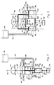
- FIGURE 5 is a diagrammatic representation of FIG. 1 .
- the float tether 86 may be connected directly to either or both of the primary piston 44 and secondary piston 66.
- the float 22 and float tether 86 upstroke the pistons 44, 66 relative to the cylinders 42, 64 as the float 22 rises with rising wave action.
- the upstroking motion of the pistons 44, 66 reduces the volumetric or fluid capacity of the pumping chambers 60, 76 and thereby pumps fluid from the pumping chamber 60, 76.
- connection of the float 22 to the pistons 44, 66 passes through at least one of the primary pumping chamber 60 or the secondary pumping chamber 76 and the piston yoke 102 passes through both pumping chambers 60, 76, it is preferred to connect the float 22 or float tether 86 to the piston yoke 102 outside the pumping chambers 60, 76, as exemplified in FIGURE 5. This eliminates the need for perforating one of the pumping chambers 60, 76 for the float tether 86 and helps to minimize the loss of pressurized fluid from the pumping chambers 60, 76.
- the piston yoke 102 is rigid or stiff and its passage through the walls of the pumping chambers 60, 76 should effect a better slidable seal with the perforation or packing around the perforation, since the motion of a rigid rod-like yoke 102 is more limited and uniform than the motion of a flexible tether. If the float tether 86 extends into a pumping chamber 60, 76, it is recommended that the portion of the tether which forms the slidable seal with the wall of pumping chamber 60, 76 be made of a stiff or rigid rod-like material.
- the piston yoke 102 may extend out the second ends 56,72 of the cylinders 42, 64 if a float tether 86 is connected to one or both of the pistons 44, 66.
- Multiple floats 22 may be connected to the piston yoke 102 or multiple floats 22 and float tethers 86 may be connected independently or unitedly to the pistons 44, 66 although the use of one float 22 is recommended as more expedient.
- the float tether 86 should be connected to distribute the buoyant forces of the float 22 on the pistons 44, 66 as evenly as possible, considering the relative sizes and pumping loads of the pistons 44, 66.
- the anchor tether 88 is connected to one or both of the primary cylinder 42 and secondary cylinder 64 and should be connected to distribute the forces exerted by the anchor 30 on the cylinders 42, 64 as evenly as possible. If a cylinder yoke 104, as illustrated in FIGURE 5 is used, the anchor tether 88 may be connected to the cylinder yoke 104. Multiple anchors 30 and anchor tethers 88 may be used, although a single anchor 30 is recommended as more expedient.
- FIGURE 6 is a diagrammatic representation of FIG. 1 .
- the anchor tether 88 may be connected directly to either or both of the primary piston 44 and the secondary piston 66. Since the connection of the anchor 30 to the pistons 44, 66 passes through at least one of the primary pumping chamber 60 or the secondary pumping chamber 76 and the piston yoke 102 passes through both pumping chambers 60, 76, it is preferred to connect the anchor 30 or anchor tether 88 to the piston yoke 102 outside the pumping chambers 60, 76, exemplified in FIGURE 6. This eliminates the need to perforate one of the pumping chambers 60, 76 for the anchor tether 88 and helps to minimize the loss of pressurized fluid from the pumping chambers 60, 76.
- the piston yoke 102 is rigid or stiff and its passage through the walls of the pumping chambers 60, 76 should effect a better slidable seal with the perforation or packing around the perforation, since the motion of a rigid rod-like yoke 102 is more limited and uniform than the motion of a flexible tether. If the anchor tether 88 extends into the pumping chamber 60, 76, it is recommended that the portion of the tether which forms the slidable seal with the pumping chamber 60, 76 be made of a stiff or rigid rod-like material.
- the piston yoke 102 may extend out the second ends 56, 72 of the cylinders 42, 64 if an anchor tether 88 is connected to one or both of the pistons 44, 66.
- Multiple anchors 30 may be connected to the piston yoke 102 or multiple anchors 30 and anchor tethers 88 may be connected independently or unitedly to the pistons 44, 66, although the use of one anchor 30 is recommended as more expedient.
- the anchor tether 88 should be connected to distribute the forces of the anchor 30 on the pistons 44, 66 as evenly as possible, considering the relative sizes and pumping loads of the pistons 44, 66.
- the float tether 86 is connected to either one or both of the primary cylinder 42 and secondary cylinder 64 and should be connected to distribute the buoyant forces exerted by the float 22 on the cylinders 42, 64 as evenly as possible.
- the float 22 and float tether 86 upstroke the cylinders 42, 64 as the float 22 rises with rising wave action.
- the volumetric or fluid capacity of the pumping chambers 60, 76 is reduced and fluid is pumped from the pumping chamber 60, 76.
- the float tether 86 may be connected to the cylinder yoke 104. Multiple floats 22 and float tethers 86 may be used although a single float 22 is recommended as more expedient.
- FIGURE 7 is a diagrammatic representation of FIG. 1 .
- a first yoke 106 yokes the secondary cylinder 64 to the primary piston 44 and a second yoke 108 yokes the primary cylinder 42 to the secondary piston 66.
- the float 22 is connected to at least one of the secondary cylinder 64 and the primary piston 44 and upstrokes the secondary cylinder 64 and the primary piston 44 relative to the primary cylinder 42 and secondary piston 66 as the float 22 rises with rising wave action. This upstroking motion of the secondary cylinder 64 and primary piston 44 reduces the volumetric or fluid capacity of the pumping chambers 60, 76 and thereby pumps fluid from the pumping chambers 60, 76.
- the anchor 30 is connected to at least one of the secondary piston 66 and primary cylinder 42 in order to anchor the secondary piston 66 and primary cylinder 42 relative to the secondary cylinder 64 and the primary piston 44.
- the first yoke 106 should retain the secondary cylinder 64 and the primary piston 44 in approximately the same position and orientations relative to one another throughout the horizontal and vertical motions of the float 22 and pumping apparatus 20 with rising and falling wave action.
- the second yoke 108 should retain the secondary piston 66 and primary cylinder 42 in approximately the same positions and orientations relative to one another throughout the horizontal and vertical motions of the float 22 and pumping apparatus 20 with rising and falling wave action.
- the first yoke 106 should transmit the downstroking motion of the secondary cylinder 64 created by the reloading pressure of the standpipe 81 as the float 22 falls with falling wave action to the primary piston 44.
- the second yoke 108 should transmit the tension between the float 22 and the anchor 30 created by the reloading pressure to the primary cylinder 42 so that the primary cylinder 42 retains its position relative to the anchor 30 as the secondary cylinder 64 and primary piston 44 downstroke with falling wave action.
- the first yoke 106 and second yoke 108 are stiff or rigid members.
- the yokes 106, 108 may be any shape, form, or material which will accomplish the purposes and functions discussed herein.
- the float tether 86 may be connected directly to either or both of the secondary cylinder 64 and primary piston 44. Since the connection of the float 22 to the piston 44 passes through the primary pumping chamber 60 and the first yoke 106 also passes through the primary pumping chamber 60, it is preferred to connect the float 22 or float tether 86 to the first yoke 106 outside the pumping chamber 60, as exemplified in FIGURE 7. This eliminates the need for perforating the pumping chamber 60 for the float tether 86 and helps to minimize the loss of pressurized fluid from the pumping chamber 60.
- the first yoke 106 is rigid or stiff and its passage through the wall of the pumping chamber 60 should effect a better slidable seal with the perforation or packing around the perforation, since the motion of a rigid rod-like yoke 106 is more limited and uniform than the motion of a flexible tether. If the float tether 86 extends into the pumping chamber 60, it is recommended that the portion of the tether 86 which forms the slidable seal with the pumping chamber 60 be made of a stiff or rigid rod-like material.
- Multiple floats 22 may be connected to the first yoke 106 or multiple floats 22 and float tethers 86 may be connected independently or unitedly to the secondary cylinder 64 and primary piston 44, although the use of one float 22 is recommended as more expedient.
- the float tether 86 should be connected to distribute the buoyant forces of the float 22 on the secondary cylinder 64 and the primary piston 44 as evenly as possible, considering the relative sizes and pumping loads of the primary piston pump 24 and secondary piston pump 26.
- the anchor tether 88 may be connected directly to either or both of the secondary piston 66 and the primary cylinder 42. Since the connection of the anchor 30 to the secondary piston 66 passes through the secondary pumping chamber 76 and the second yoke 108 passes through the pumping chamber 76, it is preferred to connect the anchor 30 or anchor tether 88 to the piston yoke 108 outside the pumping chamber 76, as exemplified in FIGURE 7. This eliminates the need for perforating the pumping chamber 76 for the anchor tether 88 and helps to minimize the loss of pressurized fluid from the pumping chamber 76.
- the second yoke 108 is rigid or stiff and its passage through the walls of the pumping chamber 76 will effect a better slidable seal with the perforation or packing around the perforation, since the motion of the rigid rod-like yoke 108 is more limited and uniform than the motion of the flexible tether. If the anchor tether 88 extends into the pumping chamber 76, it is recommended that the portion of the tether 88 which forms the slidable seal with the pumping chamber 76 be made of a stiff or rigid rod-like material.
- Anchors 30 may be connected to the second yoke 108 or multiple anchors 30 and anchor tethers 88 may be connected independently or unitedly to the secondary piston 66 and primary cylinder 42, although as discussed above, the use of one anchor 30 is preferred and is recommended as more expedient.
- the anchor tether 88 should be connected to distribute the forces of the anchor 30 on the secondary piston 66 and the primary cylinder 42 as evenly as possible, considering the relative sizes and pumping loads of the primary piston pump 24 and secondary piston pump 26.
- FIGURE 8 is a diagrammatic representation of FIG. 1 .
- a first yoke 106 yokes the secondary piston 66 to the primary cylinder 42 and a second yoke 108 yokes the secondary cylinder 64 to the primary piston 44.
- the float 22 is connected to at least one of the secondary piston 66 and the primary cylinder 42 and upstrokes the secondary piston 66 and the primary cylinder 42 relative to the secondary cylinder 64 and the primary piston 44 as the float 22 rises with rising wave action. This upstroking motion of the secondary piston 66 and primary cylinder 42 reduces the size of the pumping chambers 60, 76 and thereby pumps fluid from the pumping chamber 60, 76.
- the anchor 30 is connected to at least one of the secondary cylinder 64 and the primary piston 44 in order to anchor the secondary cylinder 64 and primary piston 44 relative to the secondary piston 66 and primary cylinder 42.
- the primary and secondary cylinders 42, 64 move relative to one another, they should not be rigidly fastened together.
- the first yoke 106 should retain the secondary piston 66 and the primary cylinder 42 in approximately the same position and orientations relative to one another throughout the horizontal and vertical motions of the float 22 and pumping apparatus 20 with rising and falling wave action.
- the second yoke 108 should retain the secondary cylinder 64 and the primary piston 44 in approximately the same positions and orientations relative to one another throughout the horizontal and vertical motions of the float 22 and pumping apparatus 20 with rising and falling wave action.
- the first yoke 106 should transmit the downstroking motion of the secondary piston 66 created by the reloading pressure of the fluid container 28 (or standpipe 81) as the float 22 falls with falling wave action to the primary cylinder 42.
- the second yoke 108 should transmit the tension between the float 22 and the anchor 30 created by the reloading pressure to the primary piston 44 so that the primary piston 44 retains its position relative to the anchor 30 as the secondary piston 66 and primary cylinder 42 downstroke with falling wave action.
- the first yoke 106 and second yoke 108 are stiff or rigid rod-like members.
- the yokes 106, 108 may be any shape, form, or material which will accomplish the purposes and functions described herein.
- the float tether 86 may be connected directly to either or both of the secondary piston 66 and the primary cylinder 42. Since the connection of the float 22 to the secondary piston 66 passes through the secondary pumping chamber 76 and the first yoke 106 also passes through the secondary pumping chamber 76, it is preferred to connect the float 22 or float tether 86 to the first yoke 106 outside the pumping chamber 76, as exemplified in FIGURE 8. This eliminates the need for perforating the pumping chamber 76 for the float tether 86 and also helps to minimize the loss of pressurized fluid from the pumping chamber 76.
- the first yoke 106 is rigid or stiff and its passage through the wall of the pumping chamber 76 should effect a better slidable seal with the perforation or packing around the perforation, since the motion of a rigid rod-like yoke 106 is more limited and uniform than the motion of a flexible tether. If the float tether 86 extends into the pumping chamber 76, it is recommended that the portion of the tether 86 which forms the slidable seal with the pumping chamber 76 be made of a stiff or rigid rod-like material.
- Multiple floats 22 may be connected to the first yoke 106 or multiple floats 22 and float tethers 86 may be connected independently or unitedly to the secondary piston 66 and primary cylinder 42, although the use of one float is recommended as more expedient.
- the float tether 86 should be connected to distribute the buoyant forces of the float 22 on the secondary piston 66 and the primary cylinder 42 as evenly as possible, considering the relative sizes and pumping loads of the primary piston pump 24 and secondary piston pump 26.
- the anchor tether 88 may be connected directly to either or both of the secondary cylinder 64 and the primary piston 44. Since the connection of the anchor 30 to the piston 44 passes through the primary pumping chamber 60 and the second yoke 108 passes through the pumping chamber 60, it is preferred to connect the anchor 30 or anchor tether 88 to the piston yoke 108 outside the pumping chamber 60, exemplified in FIGURE 8. This eliminates the need for perforating the pumping chamber 60 for the anchor tether 88 and helps to minimize the loss of pressurized fluid from the pumping chamber 60.
- the second yoke 108 is rigid or stiff and its passage through the walls of the pumping chamber 60 should effect a better slidable seal with the perforation or packing around the perforation, since the motion of the rigid rod-like yoke 108 is more limited and uniform than the motion of the flexible tether. If the anchor tether 88 extends into the primary pumping chamber 60, it is recommended that the portion of the tether 88 which forms the slidable seal with the pumping chamber 60 be made of a stiff or rigid rod-like material.
- Anchors 30 may be connected to the second yoke 108 or multiple anchors 30 and anchor tethers 88 may be connected independently or unitedly to the secondary cylinder 64 and primary piston 44, although as discussed above, the use of one anchor 30 is preferred and is recommended as more expedient.
- the anchor tether 88 should be connected to distribute the forces of the anchor 30 on the secondary cylinder 64 and primary piston 44 as evenly as possible, considering the relative sizes and pumping loads of the primary piston pump 24 and secondary piston pump 26.
- FIGURES 2, 3, 4, and 9 Common Features of FIGURES 2, 3, 4, and 9 .
- FIGURES 2, 3, 4, and 9 present example embodiments of the present invention in which the primary and secondary piston pumps 24, 26 are arranged in series so that the primary and secondary cylinders 42, 64 are arranged cylinder-end to cylinder-end between the float 22 and anchor 30.
- the cylinders 42, 64 may be axially or sequentially spaced apart between the float 22 and anchor 30.
- the cylinders 42, 64 may be non-coaxially arranged, although the cylindrical axes 58, 74 should be generally parallel.
- one end 54, 56 of the primary cylinder 42 is in physical contact with one end 70, 72 of the secondary cylinder 64. More preferably, the cylinders 42, 64 are coaxially fastened end to end, as exemplified in FIGURES 2, 3, 4, and 9.
- the cylinders 42, 64 may share a common end plate when fastened end to end.
- the coaxial arrangement of the cylinders 42, 64 is preferred to maintain linearity of the tensile forces created between the buoyancy of the float 22 and the anchor 30 and to thereby prevent the formation of torsional force couples within the pumping apparatus 20 which may be created by the existence of non-coaxial opposing forces.
- FIGURES 3 and 4 Common Features of FIGURES 3 and 4 .
- the float 22 is connected to at least one of the primary piston 44 and secondary piston 66 and upstrokes the pistons 44, 66 relative to the cylinders 42, 64 as the float 22 rises with rising wave action.
- the anchor 30 is connected to at least one of the primary cylinder 42 and the secondary cylinder 64 in order to anchor the cylinders 42, 64 relative to the pistons 44, 66.
- One or more floats 22 and float tethers 86 may be used to upstroke the pistons 44, 66 and may also be used to yoke the primary piston 44 to the secondary piston 66 so that the pistons 44, 66 are upstroked simultaneously with a rising wave.
- one or more anchors 30 and anchor tethers 88 may be used to yoke the primary cylinder 42 to the secondary cylinder 64 so that the cylinders 42, 64 effectively share a common anchor 30.
- the tension created between the secondary piston 66 and the float 22 and between the secondary cylinder 64 and the anchor 30 by the reloading pressure should be transferred to the primary cylinder 42 so that the reloading pressure will simultaneously downstroke both pistons 44, 66 relative to both cylinders 42, 64 as the float 22 falls with falling wave action.
- a piston yoke 102 yokes the primary piston 44 to the secondary piston 66 so that the pistons 44, 66 are simultaneously upstroked by the float 22 with rising wave action.
- the cylinders 42, 64 may be yoked together with a cylinder yoke (not illustrated).
- a stiff or rigid rod-like member may be used to axially or sequentially space apart the cylinders 42, 64 between the float 22 and anchor 30.
- one end 54, 56 of the primary cylinder 42 is coaxially fastened to one end 70, 72 of the secondary cylinder, as exemplified in FIGURES 3 and 4, and the cylinders 42, 64 may share a common end plate.
- the cylinders 42, 64 may be fastened together by chemical bonding, welding, mechanical fasteners, or similar fastening.
- FIGURE 4 is a diagrammatic representation of FIG. 1 .
- the float 22 is connected to the primary piston 44
- the anchor 30 is connected to the secondary cylinder 64
- the second end 56 of the primary cylinder 42 is coaxially fastened to the first end 70 of the secondary cylinder 64.
- the primary piston 44, piston yoke 102, and secondary piston 66 are upstroked relative to the primary and secondary cylinders 42, 64 thereby reducing the volumetric or fluid capacity of the pumping chambers 60, 76 and pumping fluid from the pumping chambers 60, 76.
- the reloading pressure exerted by the fluid in the fluid container 28 through the bidirectional conduit 80 expands the secondary pumping chamber 76 and downstrokes the secondary piston 66 relative to the secondary cylinder 64.
- the forces exerted by the reloading pressure are transferred from the secondary piston 66 to the primary piston 44 by piston yoke 102 and are transferred from the secondary cylinder 64 to the primary cylinder 42 by the cylinder yoke or fastening together of the cylinders 42, 64.
- Piston yoke 102 may be a flexible tether since the tension created between the secondary piston 66 and the buoyancy of the float 22 by the reloading pressure will maintain tension in the piston yoke 102.
- the piston yoke 102 be a stiff or rigid rod-like member and that the portion of the float tether 86 which extends through the wall of the primary pumping chamber 60 and into the pumping chamber 60 be a stiff or rigid rod-like member in order to effect a better slidable seal with the perforations or packing around the perforations in the walls of the primary and secondary pumping chambers 60, 76 through which the float tether 86 and piston yoke 102 pass.
- FIGURE 3 is a diagrammatic representation of FIG. 1 .
- the float 22 is connected to the secondary piston 66, the anchor 30 is connected to the primary cylinder 42, and the second end 72 of the secondary cylinder 64 is coaxially fastened to the first end 54 of the primary cylinder 42.
- the secondary piston 66, piston yoke 102, and primary piston 44 are upstroked relative to the primary and secondary cylinders 42, 64 thereby reducing the volumetric or fluid capacity of the pumping chambers 60, 76 and pumping fluid from the pumping chambers 60, 76.
- the reloading pressure exerted by the fluid in the fluid container 28 (or standpipe 81) through the bidirectional conduit 80 in the secondary pumping chamber 76 expands the secondary pumping chamber 76 and downstrokes the secondary piston 66 relative to the secondary cylinder 64.
- the forces exerted by the reloading pressure are transferred from the secondary piston 66 to the primary piston 44 by piston yoke 102 and are transferred from the secondary cylinder 64 to the primary cylinder 42 by the cylinder yoke or fastening together of the cylinders 42, 64.
- Piston yoke 102 should be a stiff or rigid rod-like member in order to transfer the downstroking motion of the secondary piston 66 to the primary piston 44 as the float 22 falls with falling wave action. Since the float tether 86 passes through the wall of the secondary pumping chamber 76, it is preferred that the portion of the float tether 86 which extends through the wall of the secondary pumping chamber 76 and into the pumping chamber 76 be a stiff or rigid rod-like member in order to effect a better slidable seal with the perforation or packing around the perforation in the wall of the pumping chamber 76 through which the float tether 86 passes.
- FIGURES 2 and 9 Common Features of FIGURES 2 and 9 .
- the float 22 is connected to at least one of the primary cylinder 42 and secondary cylinder 64 and upstrokes the cylinders 42, 64 relative to the pistons 44, 66 as the float 22 rises with rising wave action.
- the anchor 30 is connected to at least one of the primary piston 44 and the secondary piston 66 in order to anchor the pistons 44, 66 relative to the cylinders 42, 64.
- One or more floats 22 and float tethers 86 may be used to upstroke the cylinders 42, 64 and may also be used to yoke the primary cylinder 42 to the secondary cylinder 64 so that the cylinders 42, 64 are upstroked simultaneously with the rising wave.
- one or more anchors 30 and anchor tethers 88 may be used to yoke the primary piston 44 to the secondary piston 66 so that: the pistons 44, 66 effectively share a common anchor 30, the tension created between the secondary piston 66 and the anchor 30 and between the secondary cylinder 64 and the float 22 by the reloading pressure is transferred to the primary piston 44, and the reloading pressure will simultaneously downstroke both cylinders 42, 64 relative to both pistons 44, 66 as the float 22 falls with falling wave action.
- a piston yoke 102 yokes the primary piston 44 to the secondary piston 66 so that the pistons 44, 66 are simultaneously downstroked relative to the cylinders 42, 64 by the anchor 30 as the float 22 and cylinders 42, 64 rise with rising wave action.
- the cylinders 42, 64 may be yoked together with a cylinder yoke (not illustrated) similar to the yoke 104 of FIGURE 2.
- a stiff or rigid rod-like yoke may be used to axially or sequentially space apart the cylinders 42, 64 between the float 22 and anchor 30.
- one end 54, 56 of the primary cylinder 42 is coaxially fastened to one end 70, 72 of the secondary cylinder 64, as exemplified in FIGURES 2 and 9, and the cylinders 42, 64 may share a common end plate.
- the cylinders 42, 64 may be fastened together by chemical bonding, welding, mechanical fasteners, or similar fastening.
- FIGURE 2 is a diagrammatic representation of FIG. 1 .
- the float 22 is connected to the primary cylinder 42, the anchor 30 is connected to the secondary piston 66, and the first end 54 of the primary cylinder 42 is coaxially fastened to the second end 72 of the secondary cylinder 64.
- the primary cylinder 42 and secondary cylinder 44 are upstroked relative to the primary and secondary pistons 44, 66 thereby reducing the volumetric or fluid capacity of the pumping chambers 60, 76 and pumping fluid from the pumping chambers 60, 76.
- the reloading pressure exerted by the fluid in the fluid container 28 (or standpipe 81) through the bidirectional conduit 80 expands the secondary pumping chamber 76 and downstrokes the secondary cylinder 64 relative to the secondary piston 66.
- the forces exerted by the reloading pressure are transferred from the secondary piston 66 to the primary piston 44 by piston yoke 102 and are transferred from the secondary cylinder 64 to the primary cylinder 42 by the cylinder yoke or fastening together of the cylinders 42, 64.
- Piston yoke 102 should be a rigid or stiff rod-like member so that the primary piston 44 is able to use the tension in the anchor tether 88 to maintain its position relative to the anchor 30 as the primary cylinder 42 downstrokes with falling wave action. Since the anchor tether 88 and piston yoke 102 pass through the walls of the pumping chambers 60, 76, it is preferred that the portion of the anchor tether 88 which extends through the wall of the secondary pumping chamber 76 and into the pumping chamber 76 be a stiff or rigid rod-like member and that the piston yoke 102 be a rigid or stiff rod-like member in order to effect a better slidable seal with the perforation or packing around the perforations in the walls of the primary and secondary pumping chambers 60, 76 through which the piston yoke 102 and anchor tether 88 pass.
- FIGURE 9 is a diagrammatic representation of FIG. 1 .
- the float 22 is connected to the secondary cylinder 64, the anchor 30 is connected to the primary piston 44, and the first end 70 of the secondary cylinder 64 is coaxially fastened to the second end 56 of the primary cylinder 42.
- the secondary cylinder 64 and primary cylinder 42 are upstroked relative to the primary and secondary pistons 44, 66 thereby reducing the volumetric or fluid capacity of the pumping chambers 60, 76 and pumping fluid from the pumping chambers 60, 76.
- the reloading pressure exerted by the fluid and the fluid container 28 (or standpipe 81) through the bidirectional conduit 80 expands the secondary pumping chamber 76 and downstrokes the secondary cylinder 64 relative to the secondary piston 66.
- the forces exerted by the reloading pressure are transferred from the secondary piston 66 to the primary piston 44 by piston yoke 102 and are transferred from the secondary cylinder 64 to the primary cylinder 42 by the cylinder yoke or fastening together of the cylinders 42, 64.
- Piston yoke 102 may be a flexible tether since the tension created between the secondary piston 66 and the anchor 30 will maintain tension in the piston yoke 102.
- the piston yoke 102 be a stiff or rigid rod-like member and that the portion of the anchor tether 88 which extends through the wall of the primary pumping chamber 60 and into the pumping chamber 60 be a stiff or rigid rod-like member in order to effect a better slidable seal with the perforations or packing around the perforations in the walls of the primary and secondary pumping chambers 60, 76 through which the anchor tether 88 and piston yoke 102 pass.
- FIGURES 10 and 11 Common Features of FIGURES 10 and 11 .
- the primary and secondary piston pumps 24, 26 are generally concentrically and generally coaxially arranged between the float 22 and the anchor 30 so that one of the primary or secondary piston pump 24, 26 is at least partially contained within the other piston pump 24, 26.
- the secondary piston pump 26 is at least partially contained within the primary piston pump 24, since the primary piston pump 24 is the working pump or the pump which is used to pump energy for storage and should have a larger volumetric or fluid capacity, whereas the secondary piston pump 26 is normally used to reload the primary piston pump 24.
- the primary piston pump 24 may be contained within the secondary piston pump 26 if this arrangement is found to be more efficient or advantageous in a particular arrangement, construction, or system.
- piston yoke 102 yokes the primary piston 44 to the secondary piston 66 and the secondary cylinder 64 is concentrically and coaxially fastened within the primary cylinder 42.
- the cylinders 42, 64 may be fastened together by chemical bonding, welding, mechanical fasteners, or similar fastening.
- the float 22 is connected to at least one of the primary piston 44 and the secondary piston 66 for upstroking the pistons 44, 66 relative to the cylinders 42, 64 as the float 22 rises with rising wave action.
- the anchor 30 is connected to at least one of the primary cylinder 42 and the secondary cylinder 64 in order to anchor cylinders 42, 64 relative to the pistons 44, 66 and float 22.
- piston yoke 102 yokes the primary piston 44 to the secondary piston 66 and the secondary cylinder 64 is concentrically and coaxially fastened within the primary cylinder 42.
- the cylinders 42, 64 may be fastened together by chemical bonding, welding, mechanical fasteners, or similar fastening.
- the float 22 is connected to at least one of the primary cylinder 42 and secondary cylinder 64 for upstroking the cylinders 42, 64 relative to the pistons 44, 66 as the float rises with rising wave action and thereby pumping fluid from the pumping chamber 60, 76.
- the anchor 30 is connected to at least one of the primary piston 44 and secondary piston 66 for anchoring the pistons 44, 66 relative to the cylinders 42, 64 and float 22.
- FIGURES 10 and 11 are also used to illustrate variations of FIGURES 5 and 6 wherein multiple primary and/or secondary pumps 24, 26 are juxtaposingly connected between the float 22 and the anchor 30.
- the float 22 may be a surface float, semi-submersible float, submersible float, or any equivalent form of buoyant device which will capture wave energy and provide the desired lift or buoyancy.
- the anchor 30 may be a bottom anchor, a sea anchor, a drag-type anchor, or any equivalent device which will adequately oppose the rising and falling motion of the float 22.
- the float 22 (i.e., the buoyancy or lift of the float 22) is sized to provide a desired discharge pressure by multiplying the combined area of the primary piston 44 and the secondary piston 66 with the desired discharge pressure. For example, if the surface area of the primary piston 44 within the primary pumping chamber 60 is 40 square inches, and the surface area of the secondary piston 66 within the secondary pumping chamber 76 is 10 square inches and a discharge pressure of 50 pounds per square inch is required to pump fluid from the primary pumping chamber to fluid container 28 or other end user and/or to pump fluid from the secondary pumping chamber 76 into fluid container 28 or standpipe 81, the float 22 must provide 2,500 pounds of lift (50 pounds per square inch times 50 square inches equals 2,500 pounds).
- the secondary piston pump or secondary pumping means 26 should be sized to maintain sufficient tension between float 22 and anchor 30, between float 22 and the secondary pumping means 26, and between the secondary pumping means 26 and anchor 30 that the primary and secondary cylinders 42, 64 are normally retained in a generally vertical position, e.g., with the cylindrical axes 58, 74 generally vertical or generally parallel with an axis defined by the connection point 85 of the pumps 24, 26 to the float 22 and the connection point 87 of the pumps 24, 26 to the anchor 30.
- the tension should be of such magnitude that the float 22 does not drift significantly with respect to the primary and secondary pumping means 24, 26 since such drifting creates inefficiency, i.e., lost motion, and potentially destructive lateral forces on the pumping means 24, 26.
- the tension should be of such magnitude that the primary and secondary pumping means 24, 26 track the float's horizontal movement with wave action, i.e., there should be sufficient tension in the pumping apparatus 20 that the longitudinal axes of the tethers 86, 88 and cylinders 42, 64 remain generally parallel.
- the secondary pumping means or piston pump 26 should not be oversized as too much tension will inhibit the float's ability to rise with rising wave action and will inhibit the efficiency of the pumping apparatus 20. The inventor has found that the reloading force provided by the secondary piston pump 26 should be within a range of about five percent to ninety-five percent of the lift of float 22.
- the reloading force is determined by multiplying the hydrostatic head of pressure (reloading pressure) exerted on the secondary pumping chamber 76 by the fluid in bidirectional conduit 80 with the surface area of the secondary piston 66 within the secondary pumping chamber 76. For example, if the hydrostatic head of fluid provides 50 pounds per square inch reloading pressure and the area of the secondary piston 66 is 10 square inches, the reloading force is 500 pounds. At the lower end of the recommended range, the float 22 will be more sensitive to wave action and at the higher end of the range, the float 22 will ride deeper in the fluid. The range is not intended to be limiting, for example, there may be special types of floats, fluids, weather conditions, etc. in which the reloading force should be less than five percent or greater than ninety-five percent of the lift of float 22.
- the primary pumping chamber 60 have a larger volumetric capacity than the second pumping chamber 76, since the primary pumping chamber 60 is the working chamber which delivers fluid for energy for storage or use by an end user, whereas the secondary pumping chamber 76 pumps fluid to provide the energy to reload itself and the primary pumping chamber 60 or primary pumping means 24.
- the distance moved by the primary piston 44 in moving from the reloaded position 32 to the discharged position 34 should be about equal to the distance moved by the secondary piston 66 in moving from the retracted position 36 to the extended position 38. In other words, the stroke lengths of the primary piston pump 24 and secondary piston pump 26 should be approximately equal.
- the stroke lengths of the pumps 24, 26 should be sized so that the pistons 44, 66 do not strike the ends of the cylinders 42, 64 under normal operating conditions, allowing for wave height, tide cycles, variations in fluid flow through the body of fluid, etc.
- Such sizing allows the reloading pressure to continuously maintain resilient tension between the float 22 and anchor 30, between the pumps 24, 26 and float 22, and between the pumps 24, 26 and anchor 30.
- the resilient tension created by the reloading pressure controls the motion of the pumping apparatus 20, i.e., the pumps 24, 26 track the horizontal motion of the float 22 as discussed supra, and convert the wave energy acting on the float 22 into useful pumping or reloading forces rather than uncontrolled motion and potentially destructive forces.
- the efficiency of the primary and secondary pumping chambers 60, 76 is increased by having the pumping chambers 60, 76 as fluid tight or leak free as possible at the working or discharge pressure of the chambers 60, 76.
- the perforations through the walls of the pumping chambers 60, 76 through which the yokes 102, 104 or tethers 86, 88 pass may be sealed by conventional packing boxes, stuffing glands, or equivalent sealing means 109, exemplified in FIGURES 4 and 5, to assist in sealing the chambers 60, 76 and to increase the durability of the chambers 60, 76 by reducing wear.
- FIGURE 1 represents an exemplary use of the present invention as well as a means of protecting the pumping apparatus 20 from excessive wave action.
- at least one pumping apparatus 20 is connected to a fluid container 28 or other end user.
- the fluid container 28 is located above the fluid level of the body of fluid 21 and above the pumping apparatus 20.
- the fluid container 28 may be a reservoir, surge pipe, or any means of at least temporary retaining and directing the elevated pumped fluid and the potential energy stored therein.
- An example use of the elevated fluid, illustrated in FIGURE 1, would be to operate a hydroelectric generator 110.
- outlet conduits 82 from the outlet check valves 52 of the primary pumping means 24 are connected to the fluid container 28.
- outlet conduits 82 are connected to the fluid container 28 through manifold conduit 112.
- a valve 114 is located in the manifold conduit 112 above the pumping apparatus 20 for opening and closing the communication between the pumping apparatus 20 and the fluid container 28 through the conduit 112.
- Outlet conduits 82 may also be individually connected to the fluid container 28 and may have a valve 114 in each conduit 82.
- the valve 114 may be used to protect pumping apparatus 20 by simply closing the valve 114, if the bidirectional conduits 80 are not connected to the outlet conduits 82 or manifold conduit 112. Closing the valve 114 prevents the primary pumping means 24 from discharging or pumping as the float 22 rises with rising wave action.
- the pumping apparatus 20 Since the bidirectional conduits 80 are not closed by valve 114, with each successively lower wave trough, the pumping apparatus 20 will be reloaded, i.e., the primary and secondary pumping chambers 60, 76 will be enlarged by the reloading pressure present in the bidirectional conduit 80, and as the pumping chambers 60, 76 are enlarged, the pumping apparatus 20 will draw more fluid into the primary pumping means 24 through inlet check valve 50 and the float 22 will be held at the level of the lowest wave trough.
- the valve 114 may be a manually or an automatically operated device.
- the bidirectional conduits 80 of the secondary pumping means or secondary piston pump 26 may be individually connected to fluid container 28 (not illustrated) or may be connected to the fluid container 28 through a shared conduit 116 if it is desired to protect the pumping apparatus 20 with valve 114.
- the secondary piston pump 26 may have individual standpipes 81, as discussed supra and exemplified in FIGURE 6 or 7, or may be connected to a common standpipe 81 which is isolated from fluid container 28 if it is desired to utilize valve 114 to protect the pumping apparatus 20 as discussed in the preceding paragraph. If it is not desired to protect the pumping apparatus 20 with valve 114, the bidirectional conduits 80 may be connected to manifold conduit 112 or to outlet conduits 82 as exemplified in FIGURE 4.
- Surge arresting devices may be placed in the manifold conduit 112, shared conduit 116, outlet conduit 82, and/or bidirectional conduit 80, to remove the pressure and flow pulsations or surging created by the discharge of the pumping apparatus 20.
- Such surge arresting devices can enhance the efficiency of the pumping apparatus 20, particularly if the fluid container 28 has limited capacity or if the distance between the pumping apparatus 20 and the fluid container 28 or end user is large.
- the described embodiments of the pumping apparatus 20 may be made of low cost, easily obtained and replaced components made of plastic, polymer, metal, wood, styrofoam, etc.
- the components should be selected to withstand the maximum fluid pressures expected in the pumping apparatus 20. Because the components are easily obtainable (metal, plastic, or polymeric pumps, valves, and floats are commercially available, as are cables, chains, tethers, and anchors of various materials) they may be made of cheaper materials having a limited life in order to keep the cost of the pumping apparatus 20 to a minimum.
Landscapes
- Engineering & Computer Science (AREA)
- Mechanical Engineering (AREA)
- General Engineering & Computer Science (AREA)
- Chemical & Material Sciences (AREA)
- Combustion & Propulsion (AREA)
- Other Liquid Machine Or Engine Such As Wave Power Use (AREA)
Claims (31)
- Un dispositif de pompage (20) pour pomper un fluide en utilisant l'énergie provenant de l'action de montée et de retombée des vagues dans une masse de fluide, comprenant :
au moins un flotteur (22) ;
des moyens de pompage primaires (24), reliables au flotteur (22), pour pomper le fluide lorsque le flotteur monte avec l'action de montée des vaques, les moyens de pompage primaires étant déplacés d'une position rechargée à une position déchargée lorsque le flotteur monte avec l'action de montée des vagues, pompant ainsi le fluide ;
des moyens de pompage secondaires (26), reliables au flotteur (22) et reliables à un récipient de fluide (28) s'étendant au dessus de l'appareil de pompage, pour pomper le fluide vers le récipient de fluide lorsque le flotteur monte avec l'action de montée des vagues et pour déplacer les moyens de pompage primaires de la position déchargée à la position rechargée lorsque le flotteur retombe avec l'action de retombée des vagues ;
au moins une ancre (30), reliable à au moins l'un des moyens de pompage primaires et secondaires, pour ancrer les moyens de pompage primaires et les moyens de pompages secondaires par rapport au flotteur ; et
dans lequel le fluide situé dans le récipient des fluide exerce une pression de rechargement dans les moyens de pompage secondaires, la pression de rechargement dans les moyens de pompage secondaires venant s'opposer à la poussée du flotteur. - Le dispositif de la revendication 1 :
dans lequel les moyens de pompage secondaires sont déplacés d'une position rétractée à une position déployée lorsque le flotteur monte avec l'action de montée des vagues ; et
dans lequel la pression de rechargement déplace les moyens de pompage secondaires de la position déployée à la position rétractée lorsque le flotteur retombe avec l'action de retombée des vagues, déplaçant ainsi les moyens de pompage primaires de la position déchargée à la position rechargée lorsque le flotteur retombe avec l'action de retombée des vagues. - Le dispositif de la revendication 1 :
dans lequel la pression de rechargement maintient une tension entre le flotteur et l'ancre, entre les moyens de pompage secondaires et le flotteur, et entre les moyens de pompage secondaires et l'ancre. - Le dispositif de la revendication 1 :
dans lequel les moyens de pompage primaires pompent le fluide vers le récipient de fluide lorsque le flotteur remonte avec l'action de remontée des vagues. - Le dispositif de la revendication 1, dans lequel les moyens de pompage secondaires comprennent :
une pompe à piston secondaire. - Le dispositif de la revendication 1, dans lequel les moyens de pompage primaires comprennent :
une pompe à piston primaire. - Le dispositif de la revendication 1, dans lequel les moyens de pompage primaires comprennent au moins une pompe à piston primaire et dans lequel les moyens de pompage secondaires comprennent au moins une pompe à piston secondaire ; et
dans lequel chaque pompe à piston primaire comprend :
un cylindre primaire avec une première extrémité, une seconde extrémité et un axe cylindrique s'étendant entre la première extrémité et la seconde extrémité ;
un piston primaire monté à va-et-vient dans le cylindre primaire et coopérant avec le cylindre primaire pour former une chambre de pompage primaire entre le piston primaire et la première extrémité du cylindre primaire et pour former une chambre de délestage primaire entre le piston primaire et la seconde extrémité du cylindre primaire, le piston primaire se déplaçant depuis la position rechargée, où la chambre de pompage primaire a une capacité accrue, vers la position déchargée, où la chambre de pompage primaire a une capacité réduite, lorsque le flotteur monte avec l'action de montée des vagues ;
un orifice d'admission s'étendant au travers de la pompe à piston primaire jusque dans la chambre de pompage primaire pour faire entrer le fluide vers la chambre de pompage primaire ;
un orifice d'échappement s'étendant au travers de la pompe à piston primaire jusque dans la chambre de pompage primaire pour décharger le fluide depuis la chambre de pompage primaire ;
une soupape d'arrêt d'admission, reliable à l'orifice d'admission ; et
une soupape d'arrêt d'échappement, reliable à l'orifice de sortie ; et
dans lequel chaque pompe à piston secondaire comprend :
un cylindre secondaire avec une première extrémité, une seconde extrémité et un axe cylindrique s'étendant entre la première extrémité et la seconde extrémité ;
un piston secondaire monté à va-et-vient dans le cylindre secondaire et coopérant avec le cylindre secondaire pour former une chambre de pompage secondaire entre le piston secondaire et la première extrémité du cylindre secondaire et pour former une chambre de délestage secondaire entre le piston secondaire et la seconde extrémité du cylindre secondaire, le piston secondaire se déplaçant depuis la position rétractée, où la chambre de pompage secondaire a une capacité accrue, vers la position déployée, où la chambre de pompage secondaire a une capacité réduite, lorsque le flotteur monte avec l'action de montée des vagues ;
un orifice bidirectionnel, s'étendant au travers de la pompe à piston secondaire jusque dans la chambre de pompage secondaire et reliable au récipient de fluide pour laisser passer dans les deux sens le fluide entre la chambre de pompage secondaire et le récipient de fluide ; et
dans lequel le dispositif de pompage comprend en outre :
des moyens d'interconnexion pour accroître la capacité de la chambre de pompage primaire lorsque la capacité de la chambre de pompage secondaire est accrue. - Le dispositif de la revendication 7 :
dans lequel l'ancre est reliée soit au piston primaire soit au cylindre primaire et soit au piston secondaire soit au cylindre secondaire ; et
dans lequel le flotteur est relié à l'autre organe, piston primaire ou cylindre primaire et à l'autre organe, piston secondaire ou cylindre secondaire, auquel l'ancre n'est pas reliée. - Le dispositif de pompage de la revendication 7 :
dans lequel la chambre de pompage primaire possède une plus grande capacité volumétrique que la chambre de pompage secondaire. - Le dispositif de la revendication 7 :
dans lequel la distance parcourue par le piston primaire lorsqu'il se déplace de la position rechargée à la position déchargée est approximativement égale à la distance parcourue par le piston secondaire lorsqu'il se déplace de la position rétractée à la position déployée. - Le dispositif de la revendication 7 :
dans lequel les pompes à piston primaire et secondaire sont montées en juxtaposition entre le flotteur et l'ancre, de sorte que l'axe cylindrique du cylindre primaire soit dans sons ensemble parallèle à l'axe cylindrique du cylindre secondaire. - Le dispositif de la revendication 11, dans lequel les moyens d'interconnexion comprennent :
une bride de piston bridant le piston primaire au piston secondaire ; et
une bride de cylindre bridant le cylindre primaire au cylindre secondaire ; et
dans lequel le flotteur est relié à au moins l'un des deux organes, piston primaire ou piston secondaire ; et
dans lequel l'ancre est reliée à au moins l'un des deux organes, cylindre primaire ou cylindre secondaire. - Le dispositif de la revendication 11, dans lequel les moyens d'interconnexion comprennent :
une bride de piston bridant le piston primaire au piston secondaire ; et
une bride de cylindre bridant le cylindre primaire au cylindre secondaire ; et
dans lequel le flotteur est relié à au moins l'un des deux organes, cylindre primaire ou cylindre secondaire ; et
dans lequel l'ancre est reliée à au moins l'un des deux organes, piston primaire ou piston secondaire. - Le dispositif de la revendication 11, dans lequel les moyens d'interconnexion comprennent :
une première bride reliant en les bridant le cylindre secondaire et le piston primaire ; et
une seconde bride reliant en les bridant le piston secondaire et le cylindre primaire ; et
dans lequel le flotteur est relié à au moins l'un des deux organes, cylindre secondaire ou piston primaire ; et
dans lequel l'ancre est reliée à au moins l'un des deux organes, piston secondaire ou cylindre primaire. - Le dispositif de la revendication 11, dans lequel les moyens d'interconnexion comprennent :
une première bride bridant le piston secondaire au cylindre primaire ; et
une seconde bride bridant le cylindre secondaire au piston primaire ; et
dans lequel le flotteur est relié à au moins l'un des deux éléments, piston secondaire ou cylindre primaire, et
dans lequel l'ancre est reliée à au moins l'un des deux éléments, cylindre secondaire ou piston primaire. - Le dispositif de la revendication 7 :
dans lequel les pompes à piston primaire et secondaire sont montées en série de manière que les cylindres primaire et secondaire soient placés extrémité de cylindre à extrémité de cylindre entre le flotteur et l'ancre. - Le dispositif de la revendication 16 :
dans lequel le flotteur est relié à au moins l'un des deux organes, piston primaire ou piston secondaire ; et
dans lequel l'ancre est reliée à au moins l'un des deux organes, cylindre primaire ou cylindre secondaire. - Le dispositif de la revendication 17, dans lequel les moyens d'interconnexion comprennent :
une bride de piston bridant le piston primaire au piston secondaire ; et
une bride de cylindre bridant le cylindre primaire au cylindre secondaire ; et
dans lequel le flotteur est relié au piston primaire ; et
dans lequel l'ancre est reliée au cylindre secondaire. - Le dispositif de la revendication 17, dans lequel les moyens d'interconnexion comprennent :
une bride de piston bridant le piston primaire au piston secondaire ; et
une bride de cylindre bridant le cylindre primaire au cylindre secondaire ; et
dans lequel le flotteur est relié au cylindre secondaire ; et
dans lequel l'ancre est reliée au cylindre primaire. - Le dispositif de la revendication 16 :
dans lequel le flotteur est relié à au moins l'un des deux organes, cylindre primaire ou cylindre secondaire ; et
dans lequel l'ancre est reliée à au moins l'un des deux organes, piston primaire ou piston secondaire. - Le dispositif de la revendication 20, dans lequel les moyens d'interconnexion comprennent :
une bride de piston bridant le piston primaire au piston secondaire ; et
une bride de cylindre bridant le cylindre primaire au cylindre secondaire ; et
dans lequel le flotteur est relié au cylindre primaire ; et
dans lequel l'ancre est reliée au piston secondaire. - Le dispositif de la revendication 20, dans lequel les moyens d'interconnexion comprennent :
une bride de piston bridant le piston primaire au piston secondaire ; et
une bride de cylindre bridant le cylindre primaire au cylindre secondaire ; et
dans lequel le flotteur est relié au cylindre secondaire ; et
dans lequel l'ancre est reliée au piston primaire. - Le dispositif de la revendication 7 :
dans lequel les pompes à piston primaire et secondaire sont disposées dans leur ensemble concentriquement et dans leur ensemble coaxialement entre le flotteur et l'ancre, de sorte que l'une des pompes à piston primaire ou secondaire soit au moins partiellement contenue à l'intérieur de l'autre pompe primaire ou secondaire. - Le dispositif de la revendication 23 :
dans lequel la pompe à piston secondaire est au moins partiellement contenue dans la pompe à piston primaire. - Le dispositif de la revendication 23, dans lequel les moyens d'interconnexion comprennent :
une bride de cylindre bridant le cylindre primaire au cylindre secondaire ; et
une bride de piston bridant le piston primaire au piston secondaire ; et
dans lequel le flotteur est relié à au moins l'un des deux organes, piston primaire ou piston secondaire ; et
dans lequel l'ancre est reliée à au moins l'un des deux organes, cylindre primaire ou cylindre secondaire. - Le dispositif de la revendication 23, dans lequel les moyens d'interconnexion comprennent :
une bride de cylindre bridant le cylindre primaire au cylindre secondaire ; et
une bride de piston bridant le piston primaire au piston secondaire ; et
dans lequel le flotteur est relié à au moins l'un des deux organes, cylindre primaire ou cylindre secondaire ; et
dans lequel l'ancre est reliée à au moins l'un des deux organes, piston primaire ou piston secondaire. - Un dispositif de pompage pour le pompage d'un fluide selon l'une des revendications précédentes en utilisant l'énergie provenant de l'action de montée et de retombée des vagues dans une masse de fluide, comprenant :
une pompe à piston primaire, comprenant :
un cylindre primaire ;
un piston primaire monté à va-et-vient dans le cylindre primaire et coopérant avec le cylindre primaire pour former une chambre de pompage primaire d'un côté du piston primaire et une chambre de délestage primaire de l'autre côté du piston primaire ;
un orifice d'admission s'étendant au travers de la pompe à piston primaire jusque dans la chambre de pompage primaire pour faire entrer le fluide vers la chambre de pompage primaire ;
un orifice d'échappement s'étendant au travers de la pompe à piston primaire jusque dans la chambre de pompage primaire pour décharger le fluide depuis la chambre de pompage primaire ;
une soupape d'arrêt d'admission, reliée à l'orifice d'admission ; et
une soupape d'arrêt d'échappement, reliée à l'orifice de sortie ; et
une pompe à piston secondaire, comprenant :
un cylindre secondaire ;
un piston secondaire monté à va-et-vient dans le cylindre secondaire et coopérant avec le cylindre secondaire pour former une chambre de pompage secondaire d'un côté du piston secondaire et une chambre de délestage secondaire de l'autre côté du piston secondaire ; et
un orifice bidirectionnel, s'étendant au travers de la pompe à piston secondaire jusque dans la chambre de pompage secondaire et reliable au récipient de fluide pour laisser passer dans les deux sens le fluide entre la chambre de pompage secondaire et le récipient de fluide ;
un orifice bidirectionnel, relié à un récipient de fluide s'étendant au-dessus du dispositif de pompage, pour laisser passer bidirectionnellement le fluide entre le chambre de pompage secondaire et le récipient de fluide ;
une ancre, reliée soit au piston primaire soit au cylindre primaire et reliée soit au piston secondaire soit au cylindre secondaire ; et
un flotteur, relié à l'un des deux organes, piston primaire ou cylindre primaire, et relié à l'un des deux organes, piston secondaire ou cylindre secondaire, auquel l'ancre n'est pas reliée, le flotteur déplaçant l'un des deux organes, piston primaire ou cylindre primaire, et l'un des deux organes, piston secondaire ou cylindre secondaire, auquel le flotteur est relié, par rapport à l'autre organe, piston primaire ou cylindre primaire et l'autre organe, piston secondaire ou cylindre secondaire, auquel l'ancre est reliée lorsque le flotteur est sollicité vers le haut par une action de remontée des vagues, réduisant ainsi la capacité des chambres de pompage primaire et secondaire et pompant le fluide depuis les chambres de pompage primaires et secondaires ;
des moyens d'interconnexion, montés entre les pompes à piston primaire et secondaire, pour augmenter la capacité de la chambre de pompage primaire lorsque la capacité de la chambre de pompage secondaire est accrue ; et
dans lequel le fluide situé dans le récipient de fluide exerce une pression de rechargement dans la chambre de pompage secondaire en opposition à la poussée du flotteur ; la pression de rechargement déplaçant celui des deux organes, piston secondaire ou cylindre secondaire, auquel est relié le flotteur, en augmentant la taille de la chambre de pompage secondaire et en sollicitant vers le bas le flotteur en réponse à l'action de retombée des vagues ; et déplaçant ainsi celui des deux organes, piston primaire ou cylindre primaire, auquel est relié le flotteur, en augmentant la capacité de la chambre de pompage primaire, en sollicitant vers le bas le flotteur et en tirant le fluide vers la chambre de pompage primaire au travers de la soupape d'arrêt d'admission en réponse à l'action de retombée des vagues. - Un procédé de pompage d'un fluide utilisant l'énergie provenant de l'action de montée et de retombée des vagues dans une masse de fluide, comprenant les étapes consistant à :
relier des moyens de pompages primaires (24) entre un flotteur (22) et une ancre (30) dans une masse de fluide ;
relier des moyens de pompages secondaires (26) entre un flotteur (22) et une ancre dans une masse de fluide ;
pomper le fluide avec les moyens de pompage primaires (24) lorsque le flotteur (22) monte avec l'action de montée des vagues ;
pomper le fluide vers un récipient de fluide (28) s'étendant au-dessus des moyens de pompage primaires (24) et secondaires (26) avec les moyens de pompages secondaires (26) lorsque le flotteur (22) retombe avec l'action de retombée des vagues ;
exercer une pression de rechargement sur une pompe secondaire avec le fluide situé dans le récipient de fluide (28), en opposition de la poussée du flotteur ;
utiliser la pression de rechargement pour recharger la pompe secondaire lorsque le flotteur (22) retombe avec l'action de retombée des vagues ; et
interconnecter les moyens de pompage primaires (24) et les moyens de pompage secondaires (26) de manière à recharger une pompe primaire lorsque la pompe secondaire est rechargée. - Le procédé de la revendication 28 :
dans lequel les moyens de pompage primaires et les moyens de pompage secondaires sont reliés entre un flotteur et une ancre. - Le procédé de la revendication 28 :
dans lequel l'étape consistant à pomper le fluide par les moyens de pompage primaires est définie en outre par pompage du fluide vers le récipient de fluide situé au-dessus des pompes. - Le procédé de la revendication 30, comprenant en outre l'étape consistant à :
faire fonctionner un générateur hydroélectrique avec le fluide provenant du récipient de fluide.
Priority Applications (1)
| Application Number | Priority Date | Filing Date | Title |
|---|---|---|---|
| DE68916799T DE68916799D1 (de) | 1989-10-05 | 1989-10-05 | Durch Wellenkraft angetriebene Pumpanlage und Verfahren. |
Applications Claiming Priority (1)
| Application Number | Priority Date | Filing Date | Title |
|---|---|---|---|
| US07/239,618 US4883411A (en) | 1988-09-01 | 1988-09-01 | Wave powered pumping apparatus and method |
Publications (2)
| Publication Number | Publication Date |
|---|---|
| EP0421010A1 EP0421010A1 (fr) | 1991-04-10 |
| EP0421010B1 true EP0421010B1 (fr) | 1994-07-13 |
Family
ID=22902952
Family Applications (1)
| Application Number | Title | Priority Date | Filing Date |
|---|---|---|---|
| EP89118453A Expired - Lifetime EP0421010B1 (fr) | 1988-09-01 | 1989-10-05 | Dispositif et méthode de pompage actionné par les vagues |
Country Status (5)
| Country | Link |
|---|---|
| US (1) | US4883411A (fr) |
| EP (1) | EP0421010B1 (fr) |
| KR (1) | KR970003599B1 (fr) |
| AU (1) | AU630624B2 (fr) |
| PT (1) | PT91897B (fr) |
Families Citing this family (93)
| Publication number | Priority date | Publication date | Assignee | Title |
|---|---|---|---|---|
| WO1992010675A1 (fr) * | 1990-12-07 | 1992-06-25 | Dyno Industrier A.S | Systeme d'exploitation de l'energie houlometrice |
| AU713813B2 (en) * | 1992-06-30 | 1999-12-09 | Masayuki Kojima | Automatic pumping apparatus utilizing wave motion |
| CA2106503A1 (fr) * | 1992-10-19 | 1994-04-20 | Branislav Previsic | Dispositif de production d'energie hydrodynamique |
| GB2282644A (en) * | 1993-10-09 | 1995-04-12 | Jeffrey Lenoy Whitear | Tidal power generator |
| NL1005542C2 (nl) * | 1997-03-14 | 1998-09-15 | Zakaria Khalil Doleh | Inrichting voor de conversie van energie uit de verticale beweging van zeewater. |
| DE69817608D1 (de) * | 1997-12-03 | 2003-10-02 | William Dick | Meereswellen-energieumwandler |
| GB9804770D0 (en) * | 1998-03-07 | 1998-04-29 | Engineering Business Ltd | Apparatus for extracting power from moving water |
| US5986349A (en) * | 1998-05-18 | 1999-11-16 | Eberle; William J. | Wave enhancer for a system for producing electricity from ocean waves |
| US6388342B1 (en) * | 1999-07-28 | 2002-05-14 | Richard C. Vetterick, Sr. | Hydro electric plant |
| EP1131557A1 (fr) * | 1999-09-14 | 2001-09-12 | Giuseppe Zingale | Brise-mer modulaire flottant destine a la transformation de l'energie des vagues |
| US6768216B1 (en) * | 2000-05-26 | 2004-07-27 | Ocean Power Technologies, Inc. | Wave energy converters utilizing pressure differences |
| IES20000493A2 (en) * | 2000-06-16 | 2002-02-06 | Wavebob Ltd | Wave energy converter |
| ES2170029B1 (es) * | 2000-12-11 | 2003-11-01 | Molina Jose Antonio Serrano | Sistema de generacion de energia a partir de las olas del mar. |
| EP1364124A4 (fr) * | 2001-01-16 | 2004-04-14 | Ocean Power Technologies Inc | Amelioration portant sur un convertisseur d'energie des vagues |
| TW499543B (en) * | 2001-12-18 | 2002-08-21 | Ming-Hung Lin | Bellows type electric power generating equipment using sea wave |
| US6781253B2 (en) * | 2002-03-26 | 2004-08-24 | Edwin Newman | Converting ocean energy into electrical energy using bourdon tubes and cartesian divers |
| US6800954B1 (en) * | 2002-05-17 | 2004-10-05 | Brian K. Meano | System and method for producing energy |
| US20040071566A1 (en) * | 2002-06-24 | 2004-04-15 | Hill Richard Newton | Wave and tide actuated energy pump |
| WO2004019476A2 (fr) * | 2002-08-21 | 2004-03-04 | Am. S. Islam | Electricite gratuite grace a un transfert virtuel et sequentiel de masse par une force nette tres reduite et application de nouveaux concepts en science |
| US6953328B2 (en) * | 2002-10-10 | 2005-10-11 | Independent Natural Resources, Inc. | Buoyancy pump device |
| US7257946B2 (en) * | 2002-10-10 | 2007-08-21 | Independent Natural Resources, Inc. | Buoyancy pump power system |
| ES2224832B1 (es) * | 2003-01-10 | 2005-11-01 | Pipo Systems, S.L. | Sistema de multiple captacion y transformacion complementaria de energia a partir de las olas del mar. |
| US6930406B2 (en) * | 2003-02-19 | 2005-08-16 | W. C. Gray Montgomery | Tide compensated swell powered generator |
| AU2003261545B1 (en) * | 2003-03-28 | 2004-05-20 | Philip Malcolm Le Bas | A Pump |
| GB0309964D0 (en) * | 2003-05-01 | 2003-06-04 | Adamson Thomas | A device |
| US20050012338A1 (en) * | 2003-07-14 | 2005-01-20 | A-Hsiang Chang | Tide and wave powered generation apparatus |
| US20050129537A1 (en) * | 2003-12-13 | 2005-06-16 | Konstantinovskiy Boris D. | Wave's power-station |
| TW200523468A (en) * | 2004-01-15 | 2005-07-16 | Tah-Shan Lin | Pressure reservoir structure for use in water |
| NO322235B1 (no) * | 2004-06-23 | 2006-09-04 | Hans-Olav Ottersen | Flerfaset og flerdimensjonalt virkende bolgekonvertor. |
| NZ534415A (en) * | 2004-07-29 | 2005-11-25 | Ronald Murloe Winsloe | Modular near-shore wave-powered energy collection system |
| US6945042B1 (en) | 2004-08-27 | 2005-09-20 | Walckner James R | System for generating fluid movement |
| US8018084B2 (en) * | 2004-11-09 | 2011-09-13 | Gerald S. Rourke | Wave powered electrical generator |
| WO2006052923A1 (fr) * | 2004-11-09 | 2006-05-18 | Rourke Gerald S | Generateur electrique alimente par vague |
| NL1027469C2 (nl) * | 2004-11-10 | 2006-05-17 | Zakaria Khalil Doleh | Werkwijze en inrichting voor het opwekken van energie uit een beweging van een medium zoals zeewater. |
| BRPI0517038A (pt) * | 2004-12-16 | 2008-09-30 | Independent Natural Resources | método para gerar eletricidade |
| NO322807B1 (no) * | 2005-05-25 | 2006-12-11 | Lycro As | Anordning ved bolgepumpe |
| GB2428747B (en) * | 2005-08-02 | 2009-10-21 | Seawood Designs Inc | Wave energy conversion system |
| US7339285B2 (en) * | 2006-01-12 | 2008-03-04 | Negron Crespo Jorge | Hydroelectric wave-energy conversion system |
| EP2038546B1 (fr) * | 2006-05-16 | 2016-03-09 | Ocean Power Technologies, Inc. | Convertisseur d'énergie des vagues avec de l'air comprimé (wecwac) |
| ITGE20060064A1 (it) * | 2006-06-16 | 2007-12-17 | Enrico Bozano | Impianto per la produzione di energia elettrica dal moto ondoso. |
| US7755211B2 (en) * | 2006-06-17 | 2010-07-13 | Montgomery James Scott | Rigid structural array |
| US7535117B2 (en) * | 2006-06-17 | 2009-05-19 | Montgomery James Scott | Ocean wave power recovery and conversion spar buoy engine |
| GB2442718A (en) * | 2006-10-10 | 2008-04-16 | Iti Scotland Ltd | Wave and wind power generation system |
| US20080217919A1 (en) * | 2006-11-22 | 2008-09-11 | Shamil Sami Ayntrazi | Renewable energy wave air pump |
| US7843076B2 (en) * | 2006-11-29 | 2010-11-30 | Yshape Inc. | Hydraulic energy accumulator |
| EP1933026A1 (fr) * | 2006-12-06 | 2008-06-18 | René Schwender | Pompe pour la génération d'onde et/ou de marée |
| GB2473223A (en) * | 2007-01-25 | 2011-03-09 | Dartmouth Wave Energy Ltd | Height adjustable wave powered pump |
| FR2913728A1 (fr) * | 2007-03-14 | 2008-09-19 | Paul Guinard | Dispositif et procede pour capter une energie cinetique d'un fluide naturellement en mouvement |
| US20080272601A1 (en) * | 2007-05-04 | 2008-11-06 | Edwin Newman | Electrical energy from naturally moving fluids |
| US8007252B2 (en) * | 2007-09-26 | 2011-08-30 | Windle Tom J | Wave powered pumping apparatus |
| CN101424243B (zh) * | 2007-10-31 | 2011-04-13 | 徐旭文 | 波浪能汲水装置 |
| FR2924178B3 (fr) * | 2007-11-28 | 2010-09-03 | Emanuel Jose Fernandes | Micro centrale hydroelectrique maremotrice |
| US20090165455A1 (en) * | 2007-12-31 | 2009-07-02 | Shlomo Gilboa | Methods and apparatus for energy production |
| EP2077391A1 (fr) * | 2008-01-03 | 2009-07-08 | Padraig Molloy | Générateur de puissance de pompage |
| NO328051B1 (no) * | 2008-04-02 | 2009-11-16 | Statoilhydro Asa | Kraftverk, fremgangsmate for kraftproduksjon, samt anvendelse av kraftverket. |
| WO2009146564A1 (fr) * | 2008-04-23 | 2009-12-10 | Muench Otto | Centrale houlomotrice |
| EP2128430A1 (fr) * | 2008-05-30 | 2009-12-02 | Jeroen Lambertus Maria Bömer | Convertisseur d'énergie des vagues haute efficacité |
| US8713933B2 (en) * | 2008-05-30 | 2014-05-06 | Buoyant Energy, Llc | Apparatus and process for recovering energy from bouyancy and gravitational forces |
| GB0811280D0 (en) * | 2008-06-19 | 2008-07-30 | Wavebob Ltd | A power take off system for harnessing wave energy |
| US10352291B2 (en) * | 2008-07-07 | 2019-07-16 | Oscilla Power, Inc. | Power take off system for wave energy convertor |
| CN101624960B (zh) * | 2008-07-08 | 2011-08-17 | 徐旭文 | 波浪能转换系统 |
| GB2461859B (en) * | 2008-07-11 | 2010-08-04 | Robert Tillotson | Wave actuated pump and means of connecting same to the seabed |
| CA2734434A1 (fr) * | 2008-08-11 | 2010-02-18 | Fernando Gracia Lopez | Production d'energie electrique par le mouvement d'un corps fluide |
| US20110248503A1 (en) * | 2009-07-15 | 2011-10-13 | Ventz George A | Wave driven pump and power generation system |
| ES2387160B1 (es) * | 2009-08-24 | 2013-10-17 | Manuel Ramírez Marqués | Bomba accionada por el oleaje. |
| CN101886605A (zh) * | 2010-07-02 | 2010-11-17 | 王远飞 | 波浪发电装置 |
| KR101206396B1 (ko) | 2011-04-08 | 2012-11-29 | 토미지 와타베 | 진자형 파력발전장치의 제어장치 |
| CN102182619B (zh) * | 2011-04-21 | 2013-04-03 | 曹玉升 | 一种用海水波浪发电的机械装置 |
| WO2012166047A1 (fr) * | 2011-06-03 | 2012-12-06 | Ocean Harvesting Technologies Ab | Convertisseur d'énergie des vagues |
| US9234495B2 (en) * | 2011-06-28 | 2016-01-12 | Mark R. Anteau | Power generator |
| US9234494B2 (en) * | 2011-06-28 | 2016-01-12 | Mark R. Anteau | Power generator |
| US9038377B2 (en) * | 2011-06-28 | 2015-05-26 | Mark R. Anteau | Power generator |
| GB2501239A (en) * | 2012-03-19 | 2013-10-23 | Robert Tillotson | Wave operated pump with secondary chamber providing restoring force |
| CN102661232B (zh) * | 2012-05-11 | 2015-04-22 | 徐文 | 一种海浪发电站 |
| CN102705141A (zh) * | 2012-06-25 | 2012-10-03 | 周宏� | 一种海水收集装置及利用其发电的设备和方法 |
| US20150345462A1 (en) * | 2012-12-31 | 2015-12-03 | Yaolin Hu | Water pressurizing intergrated energy conversion and power-generation system collecting marine wave energy |
| WO2014116692A1 (fr) * | 2013-01-22 | 2014-07-31 | Anteau Mark R | Générateur d'énergie |
| US9074577B2 (en) | 2013-03-15 | 2015-07-07 | Dehlsen Associates, Llc | Wave energy converter system |
| WO2015045055A1 (fr) * | 2013-09-26 | 2015-04-02 | 木村 光照 | Système de génération d'énergie houlomotrice, et corps de transmission et unité de conversion de rotation utilisés pour celui-ci |
| ITGE20130113A1 (it) | 2013-11-19 | 2015-05-20 | Enrico Bozano | Impianto per lo sfruttamento dell¿energia del moto ondoso, particolarmente per la produzione di energia elettrica |
| CN103982368B (zh) * | 2014-06-03 | 2016-03-16 | 张金亮 | 浮箱式潮汐发电装置 |
| TWI564480B (zh) * | 2015-05-20 | 2017-01-01 | 徐照夫 | An automatic pumping method of waves |
| US10443593B2 (en) * | 2017-02-13 | 2019-10-15 | Walter Chen | Fresh water transport method utilizing anchored buoyant units powered by the changing height of a local tide |
| US12092069B2 (en) | 2017-08-29 | 2024-09-17 | Mark R. Anteau | Power generator |
| US11073139B2 (en) | 2017-08-29 | 2021-07-27 | Mark R Anteau | Power generation system |
| NO20171846A1 (no) * | 2017-11-20 | 2019-04-29 | Frode Reppe | Tidevannsdrevet sjøvannspumpe |
| CN108488052B (zh) * | 2018-05-08 | 2023-09-29 | 李汉明 | 能利用水力发电余水动能的泵 |
| CN109209746B (zh) * | 2018-10-31 | 2020-04-03 | 宁波大学 | 一种海水波浪能利用装置 |
| CN109356780B (zh) * | 2018-12-27 | 2021-01-22 | 河海大学 | 一种波浪能发电装置 |
| WO2021158238A1 (fr) * | 2020-02-07 | 2021-08-12 | The Climate Foundation | Appareil de transfert d'eau immergé |
| ES2897126A1 (es) * | 2021-06-30 | 2022-02-28 | Hidalgo Fabian Herreros | Sistema de generación de energía eléctrica y mecánica a partir de la energía undimotriz |
| WO2023028340A2 (fr) * | 2021-08-26 | 2023-03-02 | Zielinski David | Générateur flottant qui exploite l'énergie houlomotrice pour produire de l'énergie électrique utilisable |
| ES2976933A1 (es) * | 2024-03-11 | 2024-08-13 | Hidalgo Fabian Herreros | Modulo generador de energia electrica y bombeo de agua de mar a partir de la energia undimotriz |
Family Cites Families (18)
| Publication number | Priority date | Publication date | Assignee | Title |
|---|---|---|---|---|
| US3126830A (en) * | 1964-03-31 | dilliner | ||
| US831679A (en) * | 1906-02-19 | 1906-09-25 | Arthur E Pray | Pump. |
| US961401A (en) * | 1909-05-12 | 1910-06-14 | Charles O Bonney | Wave-operated pump. |
| US1516349A (en) * | 1924-03-06 | 1924-11-18 | Arthur E Rittenhouse | Wave motor |
| US3030893A (en) * | 1958-03-21 | 1962-04-24 | Donald U Shaffer | Wave motion actuated hydraulic pump |
| US3040667A (en) * | 1958-03-24 | 1962-06-26 | Donald U Shaffer | Wave motion actuated pump |
| US3289592A (en) * | 1965-02-16 | 1966-12-06 | John K Franzreb | Wave operated pump |
| US3487228A (en) * | 1967-04-17 | 1969-12-30 | Bernard Kriegel | Power generating system |
| US3930168A (en) * | 1973-12-26 | 1975-12-30 | Michael G Tornabene | Wave-action power apparatus |
| PH13254A (en) * | 1975-10-08 | 1980-02-20 | M Felizardo | An apparatus for extracting power from water waves |
| FR2334840A1 (fr) * | 1975-12-09 | 1977-07-08 | Mas Alfonso Joaquin | Dispositif pour capter l'energie des vagues et la transformer en energie electrique |
| US4076463A (en) * | 1976-10-26 | 1978-02-28 | Mordechai Welczer | Wave motor |
| US4421461A (en) * | 1979-09-17 | 1983-12-20 | University Of Delaware | Wave-powered desalination of seawater |
| US4326840A (en) * | 1980-03-10 | 1982-04-27 | University Of Delaware | Wave driven pump |
| GB2084259B (en) * | 1980-07-22 | 1984-06-13 | Kawasaki Heavy Ind Ltd | Wave activated power generation system |
| US4594853A (en) * | 1984-03-12 | 1986-06-17 | Wave Power Industries | Wave powered generator |
| HU195867B (en) * | 1984-04-02 | 1988-07-28 | Tibor Kenderi | Hydropneumatic hydraulic engine |
| US4754157A (en) * | 1985-10-01 | 1988-06-28 | Windle Tom J | Float type wave energy extraction apparatus and method |
-
1988
- 1988-09-01 US US07/239,618 patent/US4883411A/en not_active Expired - Fee Related
-
1989
- 1989-10-03 AU AU42492/89A patent/AU630624B2/en not_active Ceased
- 1989-10-04 PT PT91897A patent/PT91897B/pt not_active IP Right Cessation
- 1989-10-05 EP EP89118453A patent/EP0421010B1/fr not_active Expired - Lifetime
- 1989-10-06 KR KR1019890014367A patent/KR970003599B1/ko not_active Expired - Fee Related
Also Published As
| Publication number | Publication date |
|---|---|
| KR970003599B1 (ko) | 1997-03-20 |
| AU630624B2 (en) | 1992-11-05 |
| EP0421010A1 (fr) | 1991-04-10 |
| US4883411A (en) | 1989-11-28 |
| AU4249289A (en) | 1991-08-01 |
| PT91897A (pt) | 1991-05-22 |
| KR910008279A (ko) | 1991-05-31 |
| PT91897B (pt) | 1995-08-09 |
Similar Documents
| Publication | Publication Date | Title |
|---|---|---|
| EP0421010B1 (fr) | Dispositif et méthode de pompage actionné par les vagues | |
| EP0265594B1 (fr) | Dispositif à flotteur pour l'extraction de l'énergie des vagues | |
| US8668472B2 (en) | Wave actuated pump and means of connecting same to the seabed | |
| US4598211A (en) | Tidal energy system | |
| US4398095A (en) | Wave activated power generation system | |
| US5708305A (en) | Ocean wave energy conversion system | |
| US4742241A (en) | Wave energy engine | |
| US5473892A (en) | Apparatus for generating high pressure fluid in response to water weight changes caused by waves | |
| CN1997821A (zh) | 利用波浪运动进行发电的模块系统 | |
| WO2006122397A1 (fr) | Accumulateur de l’energie de la houle | |
| RU2567344C2 (ru) | Система для преобразования энергии волн | |
| CN110300847B (zh) | 波浪动力设备 | |
| US4125346A (en) | Random wave hydraulic engine | |
| US5349819A (en) | Apparatus for generating high pressure water in response to water weight changes caused by waves | |
| IE20180213A2 (en) | A wave-lock marine energy converter | |
| IE20180213A1 (en) | A wave-lock marine energy converter | |
| CA1314786C (fr) | Methode et appareil de pompage faisant appel a l'energie des vagues | |
| PH26206A (en) | Wave powered pumping apparatus and method | |
| JPH03124973A (ja) | 波動ポンプ装置および方法 | |
| US4231712A (en) | Sea water lifting device | |
| JPH0329584Y2 (fr) | ||
| US4426197A (en) | Apparatus for the conversion of power strokes of a random sequence and of random lengths of strokes into potential energy | |
| JPH07103840B2 (ja) | 高圧空気製造装置 | |
| AU2013203488B2 (en) | Wave Energy Conversion | |
| US8147212B2 (en) | Wave driven air compressor |
Legal Events
| Date | Code | Title | Description |
|---|---|---|---|
| PUAI | Public reference made under article 153(3) epc to a published international application that has entered the european phase |
Free format text: ORIGINAL CODE: 0009012 |
|
| 17P | Request for examination filed |
Effective date: 19891005 |
|
| AK | Designated contracting states |
Kind code of ref document: A1 Designated state(s): BE DE ES FR GB NL SE |
|
| 17Q | First examination report despatched |
Effective date: 19920525 |
|
| GRAA | (expected) grant |
Free format text: ORIGINAL CODE: 0009210 |
|
| AK | Designated contracting states |
Kind code of ref document: B1 Designated state(s): BE DE ES FR GB NL SE |
|
| PG25 | Lapsed in a contracting state [announced via postgrant information from national office to epo] |
Ref country code: NL Effective date: 19940713 Ref country code: ES Free format text: THE PATENT HAS BEEN ANNULLED BY A DECISION OF A NATIONAL AUTHORITY Effective date: 19940713 Ref country code: BE Effective date: 19940713 |
|
| REF | Corresponds to: |
Ref document number: 68916799 Country of ref document: DE Date of ref document: 19940818 |
|
| PG25 | Lapsed in a contracting state [announced via postgrant information from national office to epo] |
Ref country code: SE Effective date: 19941013 |
|
| PG25 | Lapsed in a contracting state [announced via postgrant information from national office to epo] |
Ref country code: DE Effective date: 19941014 |
|
| ET | Fr: translation filed | ||
| NLV1 | Nl: lapsed or annulled due to failure to fulfill the requirements of art. 29p and 29m of the patents act | ||
| PLBE | No opposition filed within time limit |
Free format text: ORIGINAL CODE: 0009261 |
|
| STAA | Information on the status of an ep patent application or granted ep patent |
Free format text: STATUS: NO OPPOSITION FILED WITHIN TIME LIMIT |
|
| 26N | No opposition filed | ||
| REG | Reference to a national code |
Ref country code: GB Ref legal event code: 746 Effective date: 19951107 |
|
| REG | Reference to a national code |
Ref country code: FR Ref legal event code: D6 |
|
| PGFP | Annual fee paid to national office [announced via postgrant information from national office to epo] |
Ref country code: GB Payment date: 19960919 Year of fee payment: 8 |
|
| PGFP | Annual fee paid to national office [announced via postgrant information from national office to epo] |
Ref country code: FR Payment date: 19961016 Year of fee payment: 8 |
|
| PG25 | Lapsed in a contracting state [announced via postgrant information from national office to epo] |
Ref country code: GB Free format text: LAPSE BECAUSE OF NON-PAYMENT OF DUE FEES Effective date: 19971005 |
|
| PG25 | Lapsed in a contracting state [announced via postgrant information from national office to epo] |
Ref country code: FR Free format text: THE PATENT HAS BEEN ANNULLED BY A DECISION OF A NATIONAL AUTHORITY Effective date: 19971031 |
|
| GBPC | Gb: european patent ceased through non-payment of renewal fee |
Effective date: 19971005 |
|
| REG | Reference to a national code |
Ref country code: FR Ref legal event code: ST |