EP0421049A1 - Perfectionnement dans un brûleur pour une chaudière - Google Patents
Perfectionnement dans un brûleur pour une chaudière Download PDFInfo
- Publication number
- EP0421049A1 EP0421049A1 EP90107741A EP90107741A EP0421049A1 EP 0421049 A1 EP0421049 A1 EP 0421049A1 EP 90107741 A EP90107741 A EP 90107741A EP 90107741 A EP90107741 A EP 90107741A EP 0421049 A1 EP0421049 A1 EP 0421049A1
- Authority
- EP
- European Patent Office
- Prior art keywords
- precombustion chamber
- fuel
- flameholder
- outlet
- chamber
- Prior art date
- Legal status (The legal status is an assumption and is not a legal conclusion. Google has not performed a legal analysis and makes no representation as to the accuracy of the status listed.)
- Withdrawn
Links
Images
Classifications
-
- F—MECHANICAL ENGINEERING; LIGHTING; HEATING; WEAPONS; BLASTING
- F23—COMBUSTION APPARATUS; COMBUSTION PROCESSES
- F23C—METHODS OR APPARATUS FOR COMBUSTION USING FLUID FUEL OR SOLID FUEL SUSPENDED IN A CARRIER GAS OR AIR
- F23C7/00—Combustion apparatus characterised by arrangements for air supply
Definitions
- This present invention relates to improvements in a fuel burner for an industrial boiler, particularly to improvements in a burner for low quality and low grade fuels such as coal, lignite, water-coal mixture.
- the problem the invention intends to solve is to realize in a simple way the combustion in a boiler and to reduce the production of nitrogen dioxides remarkably.
- Burners are also known which cause in the combustion supporting air a momentum substantially axial with the outlet of said air into the combustion chamber; such burners provide a strong recyrcle zone and a good combustion also with poor fuels.
- a drawback of such burners is that they must be placed outside the boiler and may be used only in a precombustion chamber so that it is not possible to use them in a twofold role of burner and preheater; furthermore, they require substantial modifications in the existing boilers.
- This present invention provides a burner which works as preheater too and affords a satisfactory combustion and reduction of NO X .
- Such a burner comprises in a known way: a first assembly for delivering into a boiler a stream of liquid fuel or of atomized coal with primary air or of water-coal mixture, said fuels being defined herebelow as - fuel - only; a second assembly for delivering into the boiler a stream of secondary air which supports the combustion; in a new way, the burner comprises a precombustion chamber extended into the boiler combustion chamber and a nozzle flameholder, opposite the outlet of fuel, which supplies fluid jets directed against said fuel stream for causing a recyrcle zone in said precombustion chamber; a third assembly is also provided for delivering into the precombustion chamber a stream of tertiary air for cooling the walls of the precombustion chamber, amplifying the recyrcle zone and moving away slags and ashes and also producing a staged combustion; a fourth assembly is provided optionally for delivering into the boiler a stream of quaternary air in order to complete the fuel combustion.
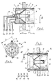
- FIG. 1 shows a burner 1 located partly in the combustion chamber 2 in a boiler 3, through a passage in the wall 4 of said boiler; a first assembly comprising a source S1 of compressed primary air and of atomized coal which are delivered by a duct 5 having the outlet in a cylindrical precombustion chamber 6 extended into the combustion chamber 2 of the boiler 3; a second assembly comprising a source S2 of compressed secondary air delivered by a duct 7 having the outlet in said precombustion chamber 6; a first raking wall 8, closed around said two outlets, which extends with a length L1 widening towards the combustion chamber 2; a second cylindrical wall 9 which extends with a length L2 in the combustion chamber 2 to form the precombustion chamber 6 and surrounds the biggest circular base of the first raking wall 8, spaced from said second cilindrical wall 9 latter, to define an annular opening 10; a third rear wall 11 which defines a chamber 12 connected by a duct 13 being part of a third assembly comprising a source S3 of compressed
- Fig. 2 shows in detail the jet flameholder 14 held by the two ducts 15 in a position opposite the exit of duct 5.
- the ends of said two ducts 15 communicate with a pipe 16 in turn communicating with two circular concentric ducts 17, 18 having equally spaced nozzles 19 on the wall opposite said outlet of duct 5; a further nozzle 19 is in the center of pipe 16.
- FIG. 3 shows an embodiment comprising all the parts comprised in the embodiment illustrated by figures 1 and 2, which parts are now illustrated and numbered in part only, in order not to involve the drawing; in addition, FIG. 3 shows parts required for supplying a quaternary air stream entering the combustion chamber 2 dawnstream with respect to the inlet of the previous three fluids, primary, secondary and tertiary, in order to improve the cooling of the walls of the precombustion chamber 6 and allow the remarkable quantity of axial motion to be maintained for causing in turn a good mixing of air and partly burnt gases in the precombustion chamber 6 as well as to allow the staged combustion is completed in zones alternatively rich and poor in fuel.
- the precombustion chamber 6 is defined by a cylindric wall 9 made by two walls 20, 21 forming a hollow space 22 affording an annular outlet 23 in the combustion chamber 2.
- the space between said walls 20, 21 communicates with a toroidal chamber 24 whereto an air stream is delivered from a source of compressed air S5, along a duct 25.
- the burner has the following further preferred features:
Landscapes
- Engineering & Computer Science (AREA)
- Chemical & Material Sciences (AREA)
- Combustion & Propulsion (AREA)
- Mechanical Engineering (AREA)
- General Engineering & Computer Science (AREA)
Applications Claiming Priority (2)
| Application Number | Priority Date | Filing Date | Title |
|---|---|---|---|
| IT2166189 | 1989-09-08 | ||
| IT8921661A IT1231511B (it) | 1989-09-08 | 1989-09-08 | Miglioramenti in un bruciatore di combustibile per una caldaia |
Publications (1)
| Publication Number | Publication Date |
|---|---|
| EP0421049A1 true EP0421049A1 (fr) | 1991-04-10 |
Family
ID=11184991
Family Applications (1)
| Application Number | Title | Priority Date | Filing Date |
|---|---|---|---|
| EP90107741A Withdrawn EP0421049A1 (fr) | 1989-09-08 | 1990-04-24 | Perfectionnement dans un brûleur pour une chaudière |
Country Status (6)
| Country | Link |
|---|---|
| US (1) | US5038722A (fr) |
| EP (1) | EP0421049A1 (fr) |
| JP (1) | JPH03105106A (fr) |
| AU (1) | AU623064B2 (fr) |
| CA (1) | CA2021475A1 (fr) |
| IT (1) | IT1231511B (fr) |
Cited By (1)
| Publication number | Priority date | Publication date | Assignee | Title |
|---|---|---|---|---|
| CN108361690A (zh) * | 2018-01-29 | 2018-08-03 | 西安交通大学 | 一种带远程燃尽风的防结渣型低NOx燃烧器 |
Families Citing this family (2)
| Publication number | Priority date | Publication date | Assignee | Title |
|---|---|---|---|---|
| CN1321290C (zh) * | 2002-12-24 | 2007-06-13 | 北京新宇阳科技有限公司 | 垃圾煤粉复合燃烧焚烧炉 |
| CA2687290C (fr) * | 2007-05-18 | 2014-05-13 | Her Majesty The Queen In Right Of Canada As Represented By The Ministeof Natural Resources | Procede de combustion de charbon a l'aide d'oxygene dans un courant de gaz de combustion recycle pour une capture de dioxyde de carbone |
Citations (4)
| Publication number | Priority date | Publication date | Assignee | Title |
|---|---|---|---|---|
| DE376570C (de) * | 1921-06-14 | 1923-05-30 | Hans Pfeil | OEl- oder Gasfeuerung |
| US2451459A (en) * | 1944-06-23 | 1948-10-19 | Stewart Warner Corp | Combustion air flow responsive carbureting apparatus |
| US3174530A (en) * | 1961-09-19 | 1965-03-23 | Cyril F Meenan | Furnace combustion chamber |
| US3363661A (en) * | 1965-12-07 | 1968-01-16 | Fletcher Co H E | Apparatus for producing a flame jet by combusting counter flow reactants |
Family Cites Families (9)
| Publication number | Priority date | Publication date | Assignee | Title |
|---|---|---|---|---|
| US3822654A (en) * | 1973-01-08 | 1974-07-09 | S Ghelfi | Burner for burning various liquid and gaseous combustibles or fuels |
| US4270895A (en) * | 1978-06-29 | 1981-06-02 | Foster Wheeler Energy Corporation | Swirl producer |
| NL7908259A (nl) * | 1979-11-12 | 1981-06-01 | Bakker A | Brander voor poedervormige brandstof. |
| DE3107649A1 (de) * | 1981-02-27 | 1982-11-11 | Steag Ag, 4300 Essen | Verfahren zum mindestens zweistufigen zuenden einer brennstaubleistungsbrennerflamme und brennsystem zur durchfuehrung des verfahrens |
| US4412810A (en) * | 1981-03-04 | 1983-11-01 | Kawasaki Jukogyo Kabushiki Kaisha | Pulverized coal burner |
| CA1176554A (fr) * | 1981-10-09 | 1984-10-23 | Shien-Fang Chang | Bruleur bicombustible pour charbon broye et mazout |
| DE3140798C2 (de) * | 1981-10-14 | 1983-12-22 | Rheinisch-Westfälisches Elektrizitätswerk AG, 4300 Essen | Zündbrenner für eine Kraftwerkskesselfeuerung |
| US4566393A (en) * | 1984-02-15 | 1986-01-28 | Connell Ralph M | Wood-waste burner system |
| US4928605A (en) * | 1985-11-15 | 1990-05-29 | Nippon Sanso Kabushiki Kaisha | Oxygen heater, hot oxygen lance having an oxygen heater and pulverized solid fuel burner |
-
1989
- 1989-09-08 IT IT8921661A patent/IT1231511B/it active
-
1990
- 1990-04-24 EP EP90107741A patent/EP0421049A1/fr not_active Withdrawn
- 1990-05-18 AU AU55191/90A patent/AU623064B2/en not_active Ceased
- 1990-05-24 US US07/528,081 patent/US5038722A/en not_active Expired - Fee Related
- 1990-06-28 JP JP2168618A patent/JPH03105106A/ja active Pending
- 1990-07-18 CA CA002021475A patent/CA2021475A1/fr not_active Abandoned
Patent Citations (4)
| Publication number | Priority date | Publication date | Assignee | Title |
|---|---|---|---|---|
| DE376570C (de) * | 1921-06-14 | 1923-05-30 | Hans Pfeil | OEl- oder Gasfeuerung |
| US2451459A (en) * | 1944-06-23 | 1948-10-19 | Stewart Warner Corp | Combustion air flow responsive carbureting apparatus |
| US3174530A (en) * | 1961-09-19 | 1965-03-23 | Cyril F Meenan | Furnace combustion chamber |
| US3363661A (en) * | 1965-12-07 | 1968-01-16 | Fletcher Co H E | Apparatus for producing a flame jet by combusting counter flow reactants |
Cited By (1)
| Publication number | Priority date | Publication date | Assignee | Title |
|---|---|---|---|---|
| CN108361690A (zh) * | 2018-01-29 | 2018-08-03 | 西安交通大学 | 一种带远程燃尽风的防结渣型低NOx燃烧器 |
Also Published As
| Publication number | Publication date |
|---|---|
| CA2021475A1 (fr) | 1991-03-09 |
| IT8921661A0 (it) | 1989-09-08 |
| US5038722A (en) | 1991-08-13 |
| JPH03105106A (ja) | 1991-05-01 |
| AU623064B2 (en) | 1992-04-30 |
| AU5519190A (en) | 1991-03-14 |
| IT1231511B (it) | 1991-12-07 |
Similar Documents
| Publication | Publication Date | Title |
|---|---|---|
| US4708638A (en) | Fluid fuel fired burner | |
| US4479442A (en) | Venturi burner nozzle for pulverized coal | |
| EP0529779B1 (fr) | Brûleurs avec production minime de NOx | |
| US4457241A (en) | Method of burning pulverized coal | |
| EP0091988B1 (fr) | Brûleur industriel et procédé pour amener d'air secondaire à un brûleur industriel | |
| KR100309667B1 (ko) | 미분탄 연소 버너 | |
| US9822967B2 (en) | Apparatus for burning pulverized solid fuels with oxygen | |
| JP4235218B2 (ja) | 燃焼用バーナおよび該バーナを備えた燃焼装置 | |
| US4602571A (en) | Burner for coal slurry | |
| JP2544662B2 (ja) | バ―ナ― | |
| EP0836048B1 (fr) | Brûleur | |
| EP0856700B1 (fr) | Bruleur de combustion et dispositif de combustion pourvu du meme | |
| US6230635B1 (en) | Device and method for combustion of fuel | |
| EP2357413A1 (fr) | Systéme de combustion sèche à faibles émissions de NOx comprenant des moyens permettant d'éliminer les bruits de combustions | |
| JPH0515924B2 (fr) | ||
| US5113771A (en) | Pulverized coal fuel injector | |
| US4285664A (en) | Burner for a plurality of fluid streams | |
| EP0421049A1 (fr) | Perfectionnement dans un brûleur pour une chaudière | |
| EP0163423A1 (fr) | Assemblage de brûleur avec partage et réglage d'écoulement et injection d'adsorbant | |
| EP0002815A2 (fr) | Dispositif pour brûler du combustible | |
| US20030157451A1 (en) | Low NOx particulate fuel burner | |
| SU1490385A1 (ru) | Вихрева пылеугольна горелка | |
| DE59305583D1 (de) | Brenner für flüssige oder gasförmige Brennstoffe | |
| SU805001A1 (ru) | Вихрева пылеугольна горелка | |
| CN101126505A (zh) | 具有中心空气射流的燃烧器 |
Legal Events
| Date | Code | Title | Description |
|---|---|---|---|
| PUAI | Public reference made under article 153(3) epc to a published international application that has entered the european phase |
Free format text: ORIGINAL CODE: 0009012 |
|
| AK | Designated contracting states |
Kind code of ref document: A1 Designated state(s): CH DE ES FR GB LI NL SE |
|
| 17P | Request for examination filed |
Effective date: 19910911 |
|
| 17Q | First examination report despatched |
Effective date: 19920901 |
|
| STAA | Information on the status of an ep patent application or granted ep patent |
Free format text: STATUS: THE APPLICATION HAS BEEN WITHDRAWN |
|
| 18W | Application withdrawn |
Withdrawal date: 19940615 |