EP0421071B1 - Ensemble de connexion à fibre optique - Google Patents
Ensemble de connexion à fibre optique Download PDFInfo
- Publication number
- EP0421071B1 EP0421071B1 EP90114091A EP90114091A EP0421071B1 EP 0421071 B1 EP0421071 B1 EP 0421071B1 EP 90114091 A EP90114091 A EP 90114091A EP 90114091 A EP90114091 A EP 90114091A EP 0421071 B1 EP0421071 B1 EP 0421071B1
- Authority
- EP
- European Patent Office
- Prior art keywords
- halves
- fibers
- fiber optic
- bore
- longitudinal
- Prior art date
- Legal status (The legal status is an assumption and is not a legal conclusion. Google has not performed a legal analysis and makes no representation as to the accuracy of the status listed.)
- Expired - Lifetime
Links
Images



Classifications
-
- G—PHYSICS
- G02—OPTICS
- G02B—OPTICAL ELEMENTS, SYSTEMS OR APPARATUS
- G02B6/00—Light guides; Structural details of arrangements comprising light guides and other optical elements, e.g. couplings
- G02B6/24—Coupling light guides
- G02B6/36—Mechanical coupling means
- G02B6/38—Mechanical coupling means having fibre to fibre mating means
- G02B6/3807—Dismountable connectors, i.e. comprising plugs
- G02B6/3809—Dismountable connectors, i.e. comprising plugs without a ferrule embedding the fibre end, i.e. with bare fibre end
-
- G—PHYSICS
- G02—OPTICS
- G02B—OPTICAL ELEMENTS, SYSTEMS OR APPARATUS
- G02B6/00—Light guides; Structural details of arrangements comprising light guides and other optical elements, e.g. couplings
- G02B6/24—Coupling light guides
- G02B6/36—Mechanical coupling means
- G02B6/38—Mechanical coupling means having fibre to fibre mating means
- G02B6/3807—Dismountable connectors, i.e. comprising plugs
- G02B6/3869—Mounting ferrules to connector body, i.e. plugs
- G02B6/387—Connector plugs comprising two complementary members, e.g. shells, caps, covers, locked together
-
- G—PHYSICS
- G02—OPTICS
- G02B—OPTICAL ELEMENTS, SYSTEMS OR APPARATUS
- G02B6/00—Light guides; Structural details of arrangements comprising light guides and other optical elements, e.g. couplings
- G02B6/24—Coupling light guides
- G02B6/36—Mechanical coupling means
- G02B6/38—Mechanical coupling means having fibre to fibre mating means
- G02B6/3807—Dismountable connectors, i.e. comprising plugs
- G02B6/381—Dismountable connectors, i.e. comprising plugs of the ferrule type, e.g. fibre ends embedded in ferrules, connecting a pair of fibres
- G02B6/3826—Dismountable connectors, i.e. comprising plugs of the ferrule type, e.g. fibre ends embedded in ferrules, connecting a pair of fibres characterised by form or shape
- G02B6/383—Hermaphroditic connectors, i.e. two identical plugs mating with one another, each plug having both male and female diametrically opposed engaging parts
-
- G—PHYSICS
- G02—OPTICS
- G02B—OPTICAL ELEMENTS, SYSTEMS OR APPARATUS
- G02B6/00—Light guides; Structural details of arrangements comprising light guides and other optical elements, e.g. couplings
- G02B6/24—Coupling light guides
- G02B6/36—Mechanical coupling means
- G02B6/38—Mechanical coupling means having fibre to fibre mating means
- G02B6/3807—Dismountable connectors, i.e. comprising plugs
- G02B6/3887—Anchoring optical cables to connector housings, e.g. strain relief features
- G02B6/3888—Protection from over-extension or over-compression
Definitions
- This invention relates to fiber optic splice assemblies in accordance with the generic clauses of claim 1 and 6. More particularly, it relates to such splice assemblies which are reuseable and which hold mated fibers in position without the agency of any additional bonding material. Further, it relates to splice assemblies which are adaptable to different sizes of fibers and are easy to assemble.
- the typical mechanical splice is not reuseable since its employment requires that the fiber be cemented therein, usually by the use of an optical adhesive. Fusion splicing is expensive and time consuming and is generally not suited for emergency field use.
- the connector approach is well-suited for joining fibers to equipment which has mating terminals but is also not suited for emergency repairs.
- the remateable splice shown in Pat. 4,787,704 is complex and expensive, and the remateable splice shown in application S.N. 07/305,350, which is assigned to the assignee of the present invention, requires the use of set screws and, thus, a screw driver.
- Other types such as those shown in the above-recited '055 patent, apply uneven compressive forces to the fibers and, further, require that both fibers be spliced simultaneously.
- Document US-A-4 824 198 discloses a fiber optic splice assembly comprising a hermaphroditic splice housing comprised of mating housing halves. Each of the halves provides a first cavity for a ferrule crimp and both of the halves, when mated, define a second cavity for an elastomeric splice.
- the splice includes a metallic sleeve and an elastomeric insert, the insert preferably offers an opening having a trianglular cross-section.
- the ferrule crimps one is provided for each of the two fibers to be spliced, also include an elastomeric insert and a ferrule crimped about the insert.
- the inset assumes a configuration dictated by the particular optical fiber cable configuration encountered.
- the housing halves are characterized by substantially indentical contours and are therefore, interchangeable.
- the housing halves contain a locking portion comprised of an integumentary layer with circumferential slots and an interior layer with mating locking flanges.
- US-A-4 822 131 discloses a hermaphroditic housing for a fiber optical splice based on the same solution principle as US-A-4 824 198.
- Yet another object of the invention is the provision of a reuseable splice.
- Still another object of the invention is the provision of a splicing system which will accommodate differences in fiber sizes.
- Yet another object of the invention is the provision of a fiber optic splice that applies even pressure thereto in a radial manner.
- An additional object includes a splice having provision for applying pressure on both the bare glass and the buffer coating of an optic fiber.
- Yet another object is the provision of a remateable splice wherein one fiber at a time may be fixed in position.
- a splice assembly which is simple to use, especially in closed environments such as the confines of a man-hole. It is reuseable and applies pressure to the fiber in a very even, circumferential manner. Further, the pressure is applied both to the fiber and its buffer coating.
- Figs. 1 and 2 two of the more commonly used sizes of optical fiber.
- the optical fiber 10 has a transparent core 12 having a diameter of 125 um with a buffer coating 14 thereon which has a diameter of 250 um.
- a strength material 16, such as Kevlar may overlie the buffer coating and an outside coating 18 can complete the package.
- the optical fiber 20 shown in Fig. 2 has a transparent core 22 having a diameter of 125 um, a buffer coating 24 having a diameter of 900 um, and a strength member 26, and outside coating 28.
- the major difference between the fibers 10 and 20 in so far as splicing them together is concerned, lies in the thickness of the buffer coating. The importance of this distinction will become apparent hereinafter.
- a fiber optic splice assembly 30 which comprises a longitudinal body 32 having an axial bore 34 therethrough.
- the body 32 has opposed ends 36 and 38 separated by and connected to a center portion 40 and preferably is made from a plastic material such as Vectra A625.
- Elastic means 42 is provided in a cavity 43 in the center portion and preferably comprises a pair of elastomeric halves as showm in U.S. Pat. No. 4,257,674, the teachings of which are hereby incorporated herein by reference.
- a cross-sectional view of the elastic means 42 is presented in Fig. 6.
- Holding means 36a and 38a are associated with the ends 36 and 38 respectively, and cooperate therewith to apply radial, circumferential compression to the ends to retain fibers therein.
- the ends 36, 38 are frusto-conical and the holdings means comprise end caps 36b, 38b which fit over the ends and which have a frusto-conical, internal bore 44.
- Each of the ends 36, 38 is provided with first and second annular, external grooves 46, 48 respectively which sequentially engage an annular, internal flange 50 formed on the leading edge 52 of the end caps and are preferably made from a plastic material such as Fluoromelt FP-EC-1004..
- the body 32 is formed from longitudinal, hermaphroditic halves 54, such as is shown in Fig. 4.
- the halves 54 are provided with projecting latches 56 on one end of the center portion 40 and with receiving slots 58 on the other end of the center portion.
- a pair of halves, one being rotated 180 degrees with respect to the other, and having the latches of one half engaged with the slots of the other half, provides a preliminary assembly.
- An end cap 36b is fitted over end 36 and an end cap 38b is fitted over end 38, in each instance with the flange 50 engaged in first annular groove 46. In this configuration the end caps are retained on the ends in a manner to allow handling and shipping. It is this configuration that could be supplied to the customer.
- the user would prepare an optical fiber leaving an appropriate length of bare fiber and and appropriate length of buffer coating and insert the terminal portions thereof into the splice assembly 30 until the respective fibers meet substantially in the middle of the assembly.
- the end caps can be provided with a marked gauge to indicate the appropriate trim length.
- FIG 3 illustrates an assembly wherein the left-hand side has an optical fiber inserted and end cap 36b in its final position, while the right-hand side has the end cap 38b still in its preliminary position with flange 50 in the first annular groove 46 and with no fiber yet in place.
- a female section 60 comprised of a rectangular slot 62 having centrally located therein a raised rib 64 having a first sector 66 and a second sector 68.
- the other end is provided with a male section 70 comprised of a pair of raised pads 72 defining therebetween a gap 74.
- the bottom of the gap (see Fig. 5) has a first sector 76 and a second sector 78, both of which are provided with a V groove 76a and 78a for receiving a fiber.
- the rib 64 has a flat surface for engaging the fiber, thus providing a receptacle similar to that shown in Pat. No. 4,257,674.
- the pads 72 fit within the rectangular slot 62 and the oppositely disposed rib 64 and bottom of gap 74 with its V groove, define therebetween the axial bore 32 for receiving the optical fiber; i.e., the buffer coating is received between 66 and 76 and the core 12 is received between 68 and 78.
- End walls 80 are each provided with a slot 82 for receiving the core 12 and leading it into elastic means 42.
- each pair will receive a single size fiber.
- two specific designs will be necessary; however, the only difference between the two modifications will be in the dimensions of the gap 74 and the width of rib 66, which will have to accommodate the different sizes of the buffer coatings.
- a first of these halves, 100 has a large internal female end 102 comprising a rectangular slot 102a having an upstanding, centrally located rib 104 therein.
- the rib is provided with a first sector 106 and a second sector 108.
- the second sector 108 is identical to sector 68; however, sector 106 is much wider to accommodate the larger diameter buffer coating of fiber 20.
- the opposite end is provided with a small internal male configuration 110 having raised pads 112 defining a gap 114 therebetween.
- the bottom of the gap 114 is the same as the bottom of gap 74, since it designed to take a fiber 10.
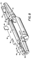
- the mating half 101 shown in Fig. 8 has a small internal female end 103 having a rectangular slot 105 with a raised rib 107 which includes sectors 109 and 111.
- the opposite end is provided with a large internal male end comprised of pads 113 defining a gap 115 therebetween.
- the bottom of the gap is configured to receive a fiber 20; i.e., it looks like the reverse of rib 104, including the appropriately dimensioned V groove.
- the latches 56 engage respective slots 58 and pads 113 of half 101 enter rectangular slot 102a of half 100.
- pads 112 enter rectangular slot 105.
- Pads 112 and. slot 105 thus form the receiving port for a fiber 10
- pads 113 and slot 102a form the receiving port for fiber 20.
- the elastic means 12 are placed in cavity 43, with an appropriate index matching gel therebetween.
- This system of splicing assemblies provides simplified manufacture and construction. No crimps are required to maintain the splice, thus, it is reuseable.
- the optical throughput can be verified and optimized, for example, by utilizing a local injection detection system. No adhesives are required and reliable field assembly is achievable without special fixtures or tools. Further, the splice can be accomplished one fiber at a time.
- the cavity 43 is be enlarged to accept a hollow sleeve 45 which can have the elastic means 42 mounted therein.
- the fiber receiving groove in the elastic means can be provided with a suitable index matching gel.
Landscapes
- Physics & Mathematics (AREA)
- General Physics & Mathematics (AREA)
- Optics & Photonics (AREA)
- Mechanical Coupling Of Light Guides (AREA)
Claims (14)
- Ensemble de jonction de fibres optiques pour connecter des fibres optiques (10, 20), le dites fibres (10, 20) ayant une âme transparente (12, 22) recouverte d'un revêtement-tampon (14, 24), le dit ensemble comprenant :
un corps longitudinal (32) percé d'un alésage axial, le dit alésage présentant des extrémités opposées (36, 38) séparées par et reliées à une partie centrale (40), une fibre (10, 20) pénétrant dans le dit corps (32) par chacune des dites extrémités (36, 38),
caractérisé en ce que
un manchon creux (45) qui se loge dans une section de contrôle élargie complémentaire du dit alésage et ayant un moyen élastique (42) disposé à l'intérieur du dit manchon creux (45) pour accueillir les âmes transparentes (12, 22) de deux fibres (10, 20) dont une partie de leur revêtement-tampon (14, 24) a été ôtée;
des moyens d'assemblage (60, 70, 102, 103, 110) formés sur la paroi interne du dit alésage aux dites extrémités (36, 38) pour accueillir une partie des fibres recouverte d'un revêtement-tampon; et
un moyen de maintien (36a, 38a) coopérant avec les dites extrémités pour appliquer une compression radiale substantiellement uniforme autour de la paroi extérieure des dites extremités (36, 38) du corps longitudinal, de telle manière que le moyen de réception puisse être compressé sur les revêtements-tampon de façon à mordre pour retenir les fibres à l'intérieur de l'ensemble. - Ensemble de jonction de fibres optiques selon la revendication 1 caractérisé en ce que la paroi extérieure des extrémités opposées (36, 38) du dit corps longitudinal (32) affecte une forme tronconique et que le dit moyen de maintien comprend des capuchons d'extrémité (36b, 38b) qui s'ajustent sur les dites extrémités, les dits capuchons d'extrémité présentant un alésage interne (44) qui est de forme tronconique.
- Ensemble de jonction de fibres optiques selon la revendication 2 caractérisé en ce que chacune des dites extrémités (36, 38) présente des première et deuxième rainures externes (46, 48) et que chacun des dits capuchons d'extrémité (36b, 38b) est pourvu d'une saillie annulaire interne (50) formée pour séquentiellement pénétrer sans pression de la dite première rainure (46) et en mode de pression radiale avec la dite deuxième rainure (48).
- Ensemble de jonction de fibres optiques selon la revendication 1 caractérisé en ce que le dit corps longitudinal (32) est constitué de deux moitiés longitudinales (54, 100, 101).
- Ensemble de jonction de fibres optiques selon la revendication 4 caractérisé en ce que les dites moitiés longitudinales (54, 100, 101) présentent des surfaces qui permettent aux deux moitiés de s'adapter l'une à l'autre pour former le dit corps longitudinal (32).
- Ensemble de jonction de fibres optiques pour connecter des fibres optiques (10, 20), le dites fibres (10, 20) ayant une âme transparente (12, 22) recouverte d'un revêtement-tampon (14, 24), le dit ensemble comprenant :
un corps longitudinal (32) percé d'un alésage axial (34) et présentant des extrémités opposées (36, 38) séparées par et reliées à une partie centrale (40);
une fibre (10, 20) pénétrant dans le dit corps (32) par chacune des dites extrémités (36, 38),
caractérisé en ce que
un manchon creux (45) qui se loge dans une section centrale élargie complémentaire du dit alésage et ayant un moyen élastique (42) disposé dans le dit manchon creux (45) pour accueillir les âmes transparentes (12, 22) de deux fibres (10, 20) dont une partie de leur revêtement-tampon (14, 24) a été ôtée;
le dit corps (32) comprenant des moitiés longitudinales (54, 100, 101), de telle manière que les dites moitiés longitudinales forment l'alésage axial (34) lorsqu'assemblées ensemble;
des moyens (60, 70, 102, 103, 110) formés sur la paroi interne du dit alésage aux dites extrémités du dit alésage axial (34) des dites moitiés longitudinales (54, 100, 101) pour accueillir une partie des fibres recouverte d'un revêtement-tampon;
de telle manière que les extrémités opposées de l'alésage présentent chacune une fente (62, 105) pratiquée dans l'une des dites moitiés (54, 100, 101) et une saillie (66, 68, 109, 111) formée sur l'autre des dites moitiés, la saillie coopérant avec une fente à chaque extrémité pour former les moyens (60, 70, 102, 110, 103) de réception des parties de fibres recouvertes d'un revêtement-tampon; et
un moyen de maintien (36a, 38a) coopérant avec les dites extrémités pour appliquer une compression radiale substantiellement uniforme autour de la paroi extérieure des dites extrémités (36, 38) du corps longitudinal, de telle manière que le moyen de réception puisse être radialement compressé sur les revêtements-tampon de façon à mordre pour retenir les fibres à l'intérieur de l'ensemble. - Ensemble de jonction de fibres optiques selon la revendication 6 caractérisé en ce que la dite fente (62, 105) est de forme quadrangulaire en coupe.
- Ensemble de jonction de fibres optiques selon la revendication 7 caractérisé en ce que la paroi extérieure des extrémités opposées (36, 38) du corps longitudinal (32) affecte une forme tronconique et que le dit moyen de maintien comprend des capuchons d'extrémité (36b, 38b) qui s'ajustent sur les dites extrémités, les dits capuchons d'extrémité présentant un alésage interne correspondant qui est de forme tronconique.
- Ensemble de jonction de fibres optiques selon la revendication 8 caractérisé en ce que chacune des dites extrémités (36, 38) présente des première et deuxième rainures externes (46, 48) et que chacun des dits capuchons d'extrémité (36b, 38b) est pourvu d'une saillie annulaire interne (50) formée pour séquentiellement pénétrer sans pression de la dite première rainure (46) et en mode de pression radiale avec la dite deuxième rainure (48).
- Système de jonction de fibres optiques pour accueillir des fibres optiques (10, 20) présentant un revêtement-tampon de tailles similaires ou distinctes, le dit système comprenant :
une première paire de moitiés de boîtier (54, 100, 101) constituant un corps (32) présentant un alésage axial avec des extrémités opposées adaptées pour accueillir deux fibres optiques (10, 20) d'une première taille similaire;
une deuxième paire de moitiés de boîtier (54, 100, 101) constituant un corps (32) présentant un alésage axial avec des extrémités opposées comportant un moyen pour accueillir deux fibres optiques (10, 20) d'une deuxième taille similaire différente de la dite première taille;
une troisième paire de moitiés de boîtier (54, 100, 101) constituant un corps présentant un alésage axial avec une extrémité prévue pour accueillir une des dites fibres optiques (10, 20) de la dite première taille et une autre extrémité prévue pour accueillir une des dites fibres optiques de la dite deuxième taille différente, chacune des dites moitiés de boîtier comprenant une partie centrale (40) comportant à l'intérieur une rigole semi-cylindrique, les dites rigoles semi-cylindriques formant une cavité cylindrique lorsque deux des dites moitiés sont réunies; et un manchon creux (45) pour inclusion à l'intérieur de la dite cavité cylindrique, le dit manchon creux (45) contenant un moyen élastique (42) pour recevoir et maintenir des fibres introduites à l'intérieur; et les dits corps (32) formés à partir des dites moitiés de boîtier (54, 100, 101) comprennent un moyen de maintien (36a, 38a) coopérant avec les dites extrémités pour appliquer une compression radiale substantiellement uniforme sur les extrémités (36, 38) de la paroi extérieure du corps longitudinal, de telle manière que le moyen de réception puisse être radialement compressé sur les revêtements-tampon de façon à mordre pour retenir les fibres à l'intérieur de l'ensemble. - Système de jonction de fibres optiques selon la revendication 10 caractérisé en ce que la paroi extérieure des extrémités opposées (36, 38) du corps longitudinal (32) affecte une forme tronconique et que le dit moyen de maintien comprend des capuchons d'extrémité (36b, 38b) qui s'ajustent sur les dites extrémités, les dits capuchons d'extrémité présentant un alésage interne correspondant (44) qui est de forme tronconique.
- Système de jonction de fibres optiques selon la revendication 11 caractérisé en ce que chacune des dites extrémités (36, 38) présente des première et deuxième rainures externes (46, 48) et que chacun des dits capuchons d'extrémité (36b, 38b) est pourvu d'une saillie annulaire interne (50) formée pour séquentiellement pénétrer sans pression de la dite première rainure (46) et en mode de pression radiale avec la dite deuxième rainure (48).
- Système de jonction de fibres optiques selon la revendication 12 caractérisé en ce que les dits corps (32) sont constitués de deux moitiés longitudinales (54, 100, 101).
- Système de jonction de fibres optiques selon la revendication 13 caractérisé en ce qu'au moins certaines des dites moitiés longitudinales (54, 100, 101) présentent des surfaces hermaphrodites qui permettent aux deux moitiés d'être réunies ensemble pour constituer le dit corps longitudinal (32).
Applications Claiming Priority (2)
| Application Number | Priority Date | Filing Date | Title |
|---|---|---|---|
| US07/415,684 US5005942A (en) | 1989-09-05 | 1989-10-02 | Fiber optic splice assembly |
| US415684 | 1989-10-02 |
Publications (2)
| Publication Number | Publication Date |
|---|---|
| EP0421071A1 EP0421071A1 (fr) | 1991-04-10 |
| EP0421071B1 true EP0421071B1 (fr) | 1994-01-05 |
Family
ID=23646745
Family Applications (1)
| Application Number | Title | Priority Date | Filing Date |
|---|---|---|---|
| EP90114091A Expired - Lifetime EP0421071B1 (fr) | 1989-10-02 | 1990-07-23 | Ensemble de connexion à fibre optique |
Country Status (3)
| Country | Link |
|---|---|
| EP (1) | EP0421071B1 (fr) |
| CA (1) | CA2020997A1 (fr) |
| DE (1) | DE69005769T2 (fr) |
Families Citing this family (4)
| Publication number | Priority date | Publication date | Assignee | Title |
|---|---|---|---|---|
| JPH06138345A (ja) * | 1992-10-27 | 1994-05-20 | Seiko Giken:Kk | 光ファイバスプライサ |
| FR2758891B1 (fr) | 1997-01-30 | 1999-06-11 | Pirelli Cables Sa | Epissure mecanique a sertir pour fibre optique |
| US6457873B1 (en) | 1998-02-23 | 2002-10-01 | Huber & Suhner Ag | Positioning system for positioning and attaching optical fibres and connectors provided with this positioning system |
| EP3362833A4 (fr) * | 2015-10-12 | 2019-05-22 | Corning Research & Development Corporation | Connecteur pour raccorder deux fibres optiques nues |
Citations (2)
| Publication number | Priority date | Publication date | Assignee | Title |
|---|---|---|---|---|
| US4822131A (en) * | 1983-10-17 | 1989-04-18 | Gte Products Corporation | Fiber optic ferrule crimp |
| US4824198A (en) * | 1983-10-17 | 1989-04-25 | Gte Products Corporation | Housing for a fiber optic splice |
Family Cites Families (2)
| Publication number | Priority date | Publication date | Assignee | Title |
|---|---|---|---|---|
| US4257674A (en) * | 1979-04-23 | 1981-03-24 | Gte Products Corporation | Elastomeric fiber optic splice |
| JPS61116303A (ja) * | 1984-11-12 | 1986-06-03 | Dai Ichi Seiko Co Ltd | 光フアイバ−カプラ− |
-
1990
- 1990-07-12 CA CA002020997A patent/CA2020997A1/fr not_active Abandoned
- 1990-07-23 DE DE90114091T patent/DE69005769T2/de not_active Expired - Fee Related
- 1990-07-23 EP EP90114091A patent/EP0421071B1/fr not_active Expired - Lifetime
Patent Citations (2)
| Publication number | Priority date | Publication date | Assignee | Title |
|---|---|---|---|---|
| US4822131A (en) * | 1983-10-17 | 1989-04-18 | Gte Products Corporation | Fiber optic ferrule crimp |
| US4824198A (en) * | 1983-10-17 | 1989-04-25 | Gte Products Corporation | Housing for a fiber optic splice |
Also Published As
| Publication number | Publication date |
|---|---|
| DE69005769T2 (de) | 1994-04-28 |
| CA2020997A1 (fr) | 1991-04-03 |
| EP0421071A1 (fr) | 1991-04-10 |
| DE69005769D1 (de) | 1994-02-17 |
Similar Documents
| Publication | Publication Date | Title |
|---|---|---|
| EP0418503B1 (fr) | Ensemble de connection à fibre optique | |
| US5005942A (en) | Fiber optic splice assembly | |
| EP0421305B1 (fr) | Ensemble de connection à fibre optique | |
| US4964688A (en) | Fiber optic connector element and method for its use | |
| US4515434A (en) | Fiber optic connector | |
| US4705352A (en) | Fiber optic connector | |
| US4715675A (en) | Fiber optic ferrule | |
| US4877303A (en) | Fiber optic connector element & method for its use | |
| US4102561A (en) | Optical waveguide connector | |
| US4818055A (en) | Optical fiber splice connector | |
| US4824198A (en) | Housing for a fiber optic splice | |
| US5125057A (en) | Optical fiber splicing device | |
| US5971626A (en) | Fiber optic connector and connector sleeve assembly | |
| TW513585B (en) | Fiber optic connector | |
| US3923371A (en) | Optical fibre connectors | |
| EP0290188A2 (fr) | Connecteur à fibres optiques | |
| CA1306376C (fr) | Raccord ajustable pour fibres optiques | |
| US4822131A (en) | Fiber optic ferrule crimp | |
| GB2312968A (en) | Clamped optic fibre connector with separable grooved bodies | |
| CN109901268A (zh) | 一种可现场拼接的光纤连接器 | |
| US4930859A (en) | Fiber optic splice assembly | |
| EP0421071B1 (fr) | Ensemble de connexion à fibre optique | |
| JP5160706B2 (ja) | 光ファイバーケーブルの端末装置 | |
| US4929046A (en) | Remateable fiber optic splice | |
| US5870514A (en) | Optical in-line elements in fiber optic systems |
Legal Events
| Date | Code | Title | Description |
|---|---|---|---|
| PUAI | Public reference made under article 153(3) epc to a published international application that has entered the european phase |
Free format text: ORIGINAL CODE: 0009012 |
|
| 17P | Request for examination filed |
Effective date: 19900723 |
|
| AK | Designated contracting states |
Kind code of ref document: A1 Designated state(s): BE DE FR GB |
|
| 17Q | First examination report despatched |
Effective date: 19920810 |
|
| RAP1 | Party data changed (applicant data changed or rights of an application transferred) |
Owner name: GTE CONTROL DEVICES INCORPORATED |
|
| RAP1 | Party data changed (applicant data changed or rights of an application transferred) |
Owner name: GTE CONTROL DEVICES OF PUERTO RICO INCORPORATED |
|
| GRAA | (expected) grant |
Free format text: ORIGINAL CODE: 0009210 |
|
| AK | Designated contracting states |
Kind code of ref document: B1 Designated state(s): BE DE FR GB |
|
| ET | Fr: translation filed | ||
| REF | Corresponds to: |
Ref document number: 69005769 Country of ref document: DE Date of ref document: 19940217 |
|
| PG25 | Lapsed in a contracting state [announced via postgrant information from national office to epo] |
Ref country code: GB Effective date: 19940723 |
|
| PG25 | Lapsed in a contracting state [announced via postgrant information from national office to epo] |
Ref country code: BE Effective date: 19940731 |
|
| PLBE | No opposition filed within time limit |
Free format text: ORIGINAL CODE: 0009261 |
|
| STAA | Information on the status of an ep patent application or granted ep patent |
Free format text: STATUS: NO OPPOSITION FILED WITHIN TIME LIMIT |
|
| 26N | No opposition filed | ||
| BERE | Be: lapsed |
Owner name: GTE CONTROL DEVICES OF PUERTO RICO INC. Effective date: 19940731 |
|
| GBPC | Gb: european patent ceased through non-payment of renewal fee |
Effective date: 19940723 |
|
| PG25 | Lapsed in a contracting state [announced via postgrant information from national office to epo] |
Ref country code: FR Effective date: 19950331 |
|
| PG25 | Lapsed in a contracting state [announced via postgrant information from national office to epo] |
Ref country code: DE Effective date: 19950401 |
|
| REG | Reference to a national code |
Ref country code: FR Ref legal event code: ST |