EP0421083B1 - Cylindre à mâchoires pour machine à imprimer - Google Patents
Cylindre à mâchoires pour machine à imprimer Download PDFInfo
- Publication number
- EP0421083B1 EP0421083B1 EP90115007A EP90115007A EP0421083B1 EP 0421083 B1 EP0421083 B1 EP 0421083B1 EP 90115007 A EP90115007 A EP 90115007A EP 90115007 A EP90115007 A EP 90115007A EP 0421083 B1 EP0421083 B1 EP 0421083B1
- Authority
- EP
- European Patent Office
- Prior art keywords
- folding
- cylinder
- jaw cylinder
- cutting
- gap
- Prior art date
- Legal status (The legal status is an assumption and is not a legal conclusion. Google has not performed a legal analysis and makes no representation as to the accuracy of the status listed.)
- Expired - Lifetime
Links
- 238000005096 rolling process Methods 0.000 claims 1
- 230000035508 accumulation Effects 0.000 description 4
- 238000009825 accumulation Methods 0.000 description 4
- 239000000463 material Substances 0.000 description 4
- 229910000639 Spring steel Inorganic materials 0.000 description 2
- 238000010276 construction Methods 0.000 description 1
- 238000012544 monitoring process Methods 0.000 description 1
Images

Classifications
-
- B—PERFORMING OPERATIONS; TRANSPORTING
- B65—CONVEYING; PACKING; STORING; HANDLING THIN OR FILAMENTARY MATERIAL
- B65H—HANDLING THIN OR FILAMENTARY MATERIAL, e.g. SHEETS, WEBS, CABLES
- B65H45/00—Folding thin material
- B65H45/12—Folding articles or webs with application of pressure to define or form crease lines
- B65H45/16—Rotary folders
- B65H45/162—Rotary folders with folding jaw cylinders
- B65H45/163—Details of folding jaws therefor
Definitions
- the invention relates to a folding apparatus with a cutting and folding bar having puncture and folding knife cylinder, on which a cutting cylinder equipped with knives is employed, and a folding jaw cylinder arranged downstream of the puncturing and folding knife cylinder.
- stoppers or other accumulations of paper or a paper jam can occur in particular between the puncture and folding knife cylinder and the folding jaw cylinder since, for example, the printed copies which are cut on the puncturing and folding knife cylinder and held only by punctures or needles can be released, with one released copy can be torn away by subsequent copies, resulting in a jam or an accumulation of paper in the gap between the folding jaw cylinder and the puncture and folding knife cylinder (center A), which, as explained above, can lead to damage. Turning the sheets over can also cause such problems. To avoid the aforementioned dangers, it is also generally known to pivot a cylinder when stoppers or paper jams occur, so that the gap between the puncturing and folding knife cylinder and folding jaw cylinder becomes sufficiently large. However, monitoring and pivoting a cylinder is relatively complex and the response time is also relatively long.
- the object of the present invention is to avoid the dangers or consequences of stoppers or a paper jam using simple and inexpensive means.
- This object is achieved in that in the circumferential direction adjacent jaws of the jaw cylinder also pits or flats extending in the axial direction of the jaw cylinder are provided, in such a way that when the gap between the jaw cylinder and the puncture and folding knife cylinder a cutting bar or respectively a grooved bar is opposite a pit or a flat.
- It is advantageous to cover the pits or flats by means of elastic elements, which are preferably arranged next to one another. These elements can be made from spring steel or from a suitable elastic plastic.
- the puncture and folding knife cylinders are usually provided or equipped with a diameter adjustment which is guided in eccentrically mounted bolts, these segments can yield in the event of a paper jam in the center between the jaw cylinder and the puncturing and folding knife cylinders.
- a stable construction is required due to the function of the grooved bar.
- the grooved bar must provide an abutment or a support for the cutting bar if an arc is cut in each case with the aid of the cutting knife in the cutting cylinder.
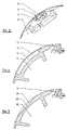
- the folding apparatus 1 shown in FIG. 1 is fed a printing material web 2 via pulling rollers 3, 4 in the usual way.
- the printing material web 2 comes between a cutting cylinder 5 and a puncturing and folding knife cylinder 6.
- the cutting cylinder 5 has two opposite knives 7 here.
- the puncture and folding knife cylinder 6 is equipped on its periphery with several cutting strips 8 and punctures 9.
- grippers can also be used within the scope of the invention in order to grasp the beginning of the supplied printing material web 2 each time before a copy is cut between a knife 7 and a cutting bar 8.
- specimens are guided over a corresponding circumferential area of the puncturing and folding knife cylinder 6, after which, with the help of the folding knife 10 of the puncturing and folding knife cylinder 6, the folding takes place, in which the folding knife 10 is on the Puncture and folding knife cylinders 6 encounter specimens lying in jaws 13 of the adjacent or subordinate jaw cylinder 12.
- the folded ones Specimens then get in the usual way along an arrow 15 into a paddle wheel 14 and from there onto a belt line 16.
- the pits 18 or the flats 20 can be provided with elastic cover elements 19, 21, for example in the form of adjacent elements made of spring steel or from a suitable elastic plastic, so that the pits 18 or flats 20 extending in the longitudinal direction of the jaw cylinder 12 are virtually bridged.
- the parts 13, 18, 19 which are present in triplicate were only provided once in FIG. 1 with reference numerals for reasons of space.
- the length of the pits 18 or of the flats 20 in the circumferential direction of the jaw cylinder 12 can be determined by experiment or the longest possible circumferential section between two adjacent jaws 13 can be used to produce the pits 18, as is the case, for example, in the embodiment according to FIG 4 is the case. This ensures that any stoppers or accumulations of paper that occur can pass through the gap between the cylinders 6, 12 without the risk of damage.
Landscapes
- Folding Of Thin Sheet-Like Materials, Special Discharging Devices, And Others (AREA)
Claims (2)
- Plieuse comportant un cylindre à pointures et couteaux plieurs (6), comportant une barrette de coupe (8) et un listeau de rainure (11) et contre lequel est appliqué un cylindre de coupe (5) équipé de couteaux (7), et comportant un cylindre à lames de pliage (12), disposé en aval du cylindre (6) à pointures et couteaux plieurs, caractérisée en ce qu'il est prévu des sillons (18) ou des méplats (20) qui s'étendent entre des lames de pliage (13), voisines dans la direction circonférentielle, du cylindre (12) à lames de pliage, également dans la direction axiale du cylindre (12) à lames de pliage de telle sorte que, lors du franchissement de la fente entre le cylindre (12) à lames de pliage et le cylindre (6) à pointures et couteaux plieurs, respectivement une barrette de coupe (8) ou un listeau de rainure (11) est disposé en vis-à-vis d'un sillon (18) ou d'un méplat (20).
- Plieuse selon la revendication 1, caractérisée en ce que les sillons (18) et le méplat (20) prévus sur le cylindre (12) à lames de pliage sont recouverts par des éléments élastiques (19,21), qui sont disposés côte-à-côte sous la forme de segments, lorsqu'on regarde dans la direction axiale du cylindre (12) à lames de pliage.
Applications Claiming Priority (2)
| Application Number | Priority Date | Filing Date | Title |
|---|---|---|---|
| DE3932931A DE3932931A1 (de) | 1989-10-03 | 1989-10-03 | Falzklappenzylinder fuer einen falzapparat |
| DE3932931 | 1989-10-03 |
Publications (3)
| Publication Number | Publication Date |
|---|---|
| EP0421083A2 EP0421083A2 (fr) | 1991-04-10 |
| EP0421083A3 EP0421083A3 (en) | 1991-05-22 |
| EP0421083B1 true EP0421083B1 (fr) | 1994-02-02 |
Family
ID=6390718
Family Applications (1)
| Application Number | Title | Priority Date | Filing Date |
|---|---|---|---|
| EP90115007A Expired - Lifetime EP0421083B1 (fr) | 1989-10-03 | 1990-08-04 | Cylindre à mâchoires pour machine à imprimer |
Country Status (4)
| Country | Link |
|---|---|
| EP (1) | EP0421083B1 (fr) |
| JP (1) | JPH03152061A (fr) |
| CA (1) | CA2026240A1 (fr) |
| DE (2) | DE3932931A1 (fr) |
Families Citing this family (6)
| Publication number | Priority date | Publication date | Assignee | Title |
|---|---|---|---|---|
| DE4344622A1 (de) * | 1993-12-24 | 1995-06-29 | Koenig & Bauer Ag | Räderfalzapparat für eine Rotationsdruckmaschine |
| US6250622B1 (en) * | 1999-05-20 | 2001-06-26 | Heidelberger Druckmaschinen Aktiengesellschaft | Cylinder assembly for a folding apparatus of a rotary printing press |
| DE10332646B4 (de) * | 2003-07-18 | 2005-11-03 | Koenig & Bauer Ag | Zylinder eines Falzapparates |
| DE102007019132B4 (de) * | 2007-04-20 | 2011-07-07 | manroland AG, 63075 | Einsatz für einen Falzklappenzylinder |
| DE102017103523A1 (de) * | 2017-02-21 | 2018-08-23 | Manroland Web Systems Gmbh | Einsatz für einen Falzklappenzylinder und Verfahren zum Herstellen eines Einsatzes für einen Falzklappenzylinder |
| DE102018108982A1 (de) * | 2018-04-16 | 2019-10-17 | Manroland Goss Web Systems Gmbh | Klemmhebel zum Anbringen von Bearbeitungswerkzeugen an einem drehbar gelagerten Element einer Druckmaschine |
Family Cites Families (6)
| Publication number | Priority date | Publication date | Assignee | Title |
|---|---|---|---|---|
| GB396486A (en) * | 1931-03-19 | 1933-08-10 | Goss Printing Press Co Ltd | Improvements in or relating to folding mechanisms for paper or similar sheets |
| SE309425B (fr) * | 1966-03-15 | 1969-03-24 | Winkler Fallert & Co Maschf | |
| DE2011661B1 (de) * | 1970-03-12 | 1971-07-15 | Maschinenfabrik Augsburg Nuernberg Ag | Falzmesszylinder für Rotationsdruckma schinen |
| DE3347719A1 (de) * | 1983-12-31 | 1985-07-11 | M.A.N.- Roland Druckmaschinen AG, 6050 Offenbach | Querfalzvorrichtung |
| DE3545295C1 (de) * | 1985-12-20 | 1986-10-16 | M.A.N.- Roland Druckmaschinen AG, 6050 Offenbach | Zugwalzenpaar fuer eine Rotationsdruckmaschine zum Transportieren von Bedruckstoffbahnen |
| DE3810439C1 (fr) * | 1988-03-26 | 1989-08-10 | Man Roland Druckmaschinen Ag, 6050 Offenbach, De |
-
1989
- 1989-10-03 DE DE3932931A patent/DE3932931A1/de active Granted
-
1990
- 1990-08-04 EP EP90115007A patent/EP0421083B1/fr not_active Expired - Lifetime
- 1990-08-04 DE DE90115007T patent/DE59004497D1/de not_active Expired - Lifetime
- 1990-09-26 CA CA002026240A patent/CA2026240A1/fr not_active Abandoned
- 1990-10-03 JP JP2263971A patent/JPH03152061A/ja active Pending
Also Published As
| Publication number | Publication date |
|---|---|
| DE3932931A1 (de) | 1991-04-11 |
| EP0421083A2 (fr) | 1991-04-10 |
| JPH03152061A (ja) | 1991-06-28 |
| DE3932931C2 (fr) | 1993-01-07 |
| CA2026240A1 (fr) | 1991-04-04 |
| EP0421083A3 (en) | 1991-05-22 |
| DE59004497D1 (de) | 1994-03-17 |
Similar Documents
| Publication | Publication Date | Title |
|---|---|---|
| EP0627310B1 (fr) | Plieuse et procédé de pliage transversal | |
| DE2517000C2 (de) | Falzapparat für quer- und längsgefalzte oder nur längsgefalzte Produkte | |
| DE3721515C1 (de) | Vorrichtung zum Verteilen von Druckexemplaren | |
| EP0421083B1 (fr) | Cylindre à mâchoires pour machine à imprimer | |
| DE4340858A1 (de) | Zylinder | |
| EP1116560B1 (fr) | Dispofitif de coupe à longueur réglable | |
| EP0019202A1 (fr) | Dispositif de pliage pour une machine rotative d'impression | |
| DE19927920A1 (de) | Schneideinrichtung im Falzapparat einer Rotationsdruckmaschine und Falzapparat mit einer solchen Schneideinrichtung | |
| CH615134A5 (en) | Folding apparatus for rotary printing machines having a magazine-cutting facility | |
| EP0264846B1 (fr) | Appareil de pliage avec dispositif de perforation transversale | |
| EP0156325B1 (fr) | Dispositif pour la fabrication d'un pli oblique au début d'une nappe continue de papier | |
| DE10254332A1 (de) | Falzzylinder | |
| DE102005041180A1 (de) | Querperforationseinheit eines Falzapparats einer Druckmaschine | |
| DE3146208A1 (de) | Falzapparat | |
| EP1186561B1 (fr) | Dispositif de coupe pour une bande dans une machine de pliage | |
| DE10110117A1 (de) | Falzzylinder mit einem Expansions-Segment | |
| DE1132935B (de) | Trommelfalzeinrichtung zum Querfalzen und Sammeln an Bogendruckmaschinen | |
| EP0029528B1 (fr) | Machine d'impression rotative à bobines avec un dispositif de raccordement pour bandes | |
| EP0703047A2 (fr) | Dispositif de perforation | |
| EP1483189A1 (fr) | Dispositif de coupe | |
| DE102016216429B4 (de) | Druckprodukt, Verfahren und Rollendruckmaschine zur Herstellung eines Druckproduktes | |
| DE102007039485A1 (de) | Verfahren zum Betreiben einer Rollendruckmaschine | |
| EP1886955B1 (fr) | Dispositif de pliage | |
| DE2524606A1 (de) | Vorrichtung zum bearbeiten von endlosformularen | |
| EP1650152A1 (fr) | Plieuse pour une machine d'impression rotative. |
Legal Events
| Date | Code | Title | Description |
|---|---|---|---|
| PUAI | Public reference made under article 153(3) epc to a published international application that has entered the european phase |
Free format text: ORIGINAL CODE: 0009012 |
|
| PUAL | Search report despatched |
Free format text: ORIGINAL CODE: 0009013 |
|
| AK | Designated contracting states |
Kind code of ref document: A2 Designated state(s): CH DE FR GB IT LI |
|
| AK | Designated contracting states |
Kind code of ref document: A3 Designated state(s): CH DE FR GB IT LI |
|
| 17P | Request for examination filed |
Effective date: 19910419 |
|
| 17Q | First examination report despatched |
Effective date: 19930331 |
|
| ITF | It: translation for a ep patent filed | ||
| GRAA | (expected) grant |
Free format text: ORIGINAL CODE: 0009210 |
|
| AK | Designated contracting states |
Kind code of ref document: B1 Designated state(s): CH DE FR GB IT LI |
|
| GBT | Gb: translation of ep patent filed (gb section 77(6)(a)/1977) |
Effective date: 19940201 |
|
| REF | Corresponds to: |
Ref document number: 59004497 Country of ref document: DE Date of ref document: 19940317 |
|
| ET | Fr: translation filed | ||
| PLBE | No opposition filed within time limit |
Free format text: ORIGINAL CODE: 0009261 |
|
| STAA | Information on the status of an ep patent application or granted ep patent |
Free format text: STATUS: NO OPPOSITION FILED WITHIN TIME LIMIT |
|
| 26N | No opposition filed | ||
| REG | Reference to a national code |
Ref country code: GB Ref legal event code: IF02 |
|
| PGFP | Annual fee paid to national office [announced via postgrant information from national office to epo] |
Ref country code: CH Payment date: 20020717 Year of fee payment: 13 |
|
| PGFP | Annual fee paid to national office [announced via postgrant information from national office to epo] |
Ref country code: GB Payment date: 20020730 Year of fee payment: 13 |
|
| PGFP | Annual fee paid to national office [announced via postgrant information from national office to epo] |
Ref country code: FR Payment date: 20020812 Year of fee payment: 13 |
|
| PG25 | Lapsed in a contracting state [announced via postgrant information from national office to epo] |
Ref country code: GB Free format text: LAPSE BECAUSE OF NON-PAYMENT OF DUE FEES Effective date: 20030804 |
|
| PG25 | Lapsed in a contracting state [announced via postgrant information from national office to epo] |
Ref country code: CH Free format text: LAPSE BECAUSE OF NON-PAYMENT OF DUE FEES Effective date: 20030831 Ref country code: LI Free format text: LAPSE BECAUSE OF NON-PAYMENT OF DUE FEES Effective date: 20030831 |
|
| GBPC | Gb: european patent ceased through non-payment of renewal fee |
Effective date: 20030804 |
|
| REG | Reference to a national code |
Ref country code: CH Ref legal event code: PL |
|
| PG25 | Lapsed in a contracting state [announced via postgrant information from national office to epo] |
Ref country code: FR Free format text: LAPSE BECAUSE OF NON-PAYMENT OF DUE FEES Effective date: 20040430 |
|
| REG | Reference to a national code |
Ref country code: FR Ref legal event code: ST |
|
| PG25 | Lapsed in a contracting state [announced via postgrant information from national office to epo] |
Ref country code: IT Free format text: LAPSE BECAUSE OF NON-PAYMENT OF DUE FEES;WARNING: LAPSES OF ITALIAN PATENTS WITH EFFECTIVE DATE BEFORE 2007 MAY HAVE OCCURRED AT ANY TIME BEFORE 2007. THE CORRECT EFFECTIVE DATE MAY BE DIFFERENT FROM THE ONE RECORDED. Effective date: 20050804 |
|
| PGFP | Annual fee paid to national office [announced via postgrant information from national office to epo] |
Ref country code: DE Payment date: 20090821 Year of fee payment: 20 |
|
| PG25 | Lapsed in a contracting state [announced via postgrant information from national office to epo] |
Ref country code: DE Free format text: LAPSE BECAUSE OF EXPIRATION OF PROTECTION Effective date: 20100804 |