EP0421096A2 - Agencement d'appareil électronique - Google Patents
Agencement d'appareil électronique Download PDFInfo
- Publication number
- EP0421096A2 EP0421096A2 EP90115492A EP90115492A EP0421096A2 EP 0421096 A2 EP0421096 A2 EP 0421096A2 EP 90115492 A EP90115492 A EP 90115492A EP 90115492 A EP90115492 A EP 90115492A EP 0421096 A2 EP0421096 A2 EP 0421096A2
- Authority
- EP
- European Patent Office
- Prior art keywords
- housing
- electronic device
- device arrangement
- arrangement according
- closure panel
- Prior art date
- Legal status (The legal status is an assumption and is not a legal conclusion. Google has not performed a legal analysis and makes no representation as to the accuracy of the status listed.)
- Withdrawn
Links
Images


Classifications
-
- H—ELECTRICITY
- H05—ELECTRIC TECHNIQUES NOT OTHERWISE PROVIDED FOR
- H05K—PRINTED CIRCUITS; CASINGS OR CONSTRUCTIONAL DETAILS OF ELECTRIC APPARATUS; MANUFACTURE OF ASSEMBLAGES OF ELECTRICAL COMPONENTS
- H05K7/00—Constructional details common to different types of electric apparatus
- H05K7/14—Mounting supporting structure in casing or on frame or rack
- H05K7/1422—Printed circuit boards receptacles, e.g. stacked structures, electronic circuit modules or box like frames
- H05K7/1424—Card cages
- H05K7/1425—Card cages of standardised dimensions, e.g. 19"-subrack
Definitions
- the invention relates to an electronic device arrangement for control panel or console installation with a jacket-like housing, one end opening of which can be closed by a closure panel, with a first printed circuit board arranged approximately parallel to the bottom surface of the housing and at least approximately vertically upward a further printed circuit board, possibly carrying electronic components, can be plugged on in an electrically connecting manner with the first printed circuit board, the first and the further printed circuit boards being able to be arranged on a printed circuit board holder, with plug connections which are electrically conductively connected to the first printed circuit board and can be connected to the lines leading to external units are.
- circuit board holder in the region of an edge of the front opening of the housing on the housing is pivotable about a pivot axis and is pivotable out of its mounting position about the pivot axis out of the housing. Due to the pivotability of the circuit board holder and the arrangement of the pivot axis in the region of the front opening of the housing, the circuit board holder can at least largely be pivoted out of the housing, so that all circuit boards are freely accessible. An installation and removal of other components is not necessary if a new assembly or re-assembly of the circuit boards he follows. Damage to other components is largely avoided.
- Such repositioning or refitting can take place without interrupting the operation of the device arrangement.
- circuit board holder is firmly connected to the closure panel and the circuit board holder and closure panel can be pivoted out of the housing about a common pivot axis. As a result, the construction effort is kept low and the assembly and disassembly of printed circuit boards is further simplified.
- the pivot axis preferably extends along the lower, approximately horizontal edge of the front opening of the housing, so that when the card holder is pivoted out, the closure panel is located under the circuit board holder and does not interfere.
- the plug connections are arranged on the closure panel in such a way that the area with the plug-in counterpart provided with the lines is directed toward the exterior of the housing, the external connections can remain connected when the circuit board holder and closure panel are folded out. You then simply swivel along with the sealing panel without any tensile or compressive load acting on the lines.
- a fan unit is arranged on the closure panel, through which the housing of one Cooling air flow through which air drawn in from the outside can flow.
- the fan unit is arranged on the inside of the closure panel, while a filter unit is arranged on the outside of the closure panel opposite the fan unit and air can be drawn in from the outside of the housing through the filter unit and a corresponding continuous recess in the connection panel by the fan unit .
- the filter unit can consist of a rigid, approximately bowl-shaped filter grill, in the shell of which a filter mat can be inserted in such a way that it is arranged between the filter grill and the continuous recess of the closure panel.
- the filter grill has one or more threaded holes into which fastening screws, which are preferably knurled screws, can be screwed through corresponding holes in the closure panel, the filter grill can be loosened and the filter mat replaced by simply loosening the knurled nuts. Since the threaded pins protrude into the housing, there are no components which protrude outwards from the housing and on which one could get caught.
- the closure panel In the closed state, the closure panel has an area which is approximately parallel to the front plane of the housing and which springs back into the interior of the housing on which the plug connections are arranged and if the recessed area also extends by approximately the length of a counterpart parallel to the plane of the housing, the counterparts do not protrude beyond the housing periphery. Loosening of the mating parts by unintentional touching is thus largely avoided. This is particularly the case when the cables come laterally from the plug-in counterparts.
- a channel results through which the lines can be routed to other external units without protruding from the housing.
- An area of the closure panel which extends approximately in the plane of the housing can adjoin the recessed area.
- the transition area between the recessed area and the area extending in the plane of the housing can be designed as a recessed grip recess in a practically recessed design.
- the closure panel is particularly easy to manufacture if it is formed from a sheet of approximately Z-shaped cross-section, one end leg of the recessed area, the other end leg of the area extending in the plane of the housing and the connecting web forms the recessed grip.
- a particularly favorable utilization of the available installation space is achieved in that the fan unit is arranged in the area of the closure panel which extends in the plane of the housing.
- the first printed circuit board can either be designed without active electronic components, or active electronic components can be arranged on the first printed circuit board.
- the housing is formed in an area with ventilation slots, between which and the aerator unit the circuit boards are arranged, so that the cooling air flow always sweeps along the circuit boards.
- the housing has an insertion area which is designed with insertion guides and has an insertion opening and into which electronic devices can be inserted to close the insertion opening, further units can be arranged in the housing in addition to the printed circuit boards.
- Plug contacts are preferably arranged in the region of the rear wall of the insertion opening, into which corresponding plug counterparts on the back of the electronic devices can be inserted in a contacting manner by inserting the electronic devices into the insertion opening. This results in simple assembly and disassembly of the other units.
- the electronic devices can be power supply modules and / or drives.
- plug contacts are connected to the first printed circuit board via electrical lines, a connection can be made in the region of the pivot axis so that this connection does not have to be released when the printed circuit board holder is pivoted out.
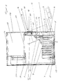
- the electronic device arrangement shown in the figures has a housing 1 which consists of sheet metal parts which are connected to one another in an electrically conductive manner, so that a shielding effect which satisfies the required interference protection is achieved.
- the lower area of the housing 1 has an end opening 2, which is closed by a closure panel 3 is lockable.
- the closure panel 3 consists of a sheet Z-shaped cross section.
- the lower end leg 4 extends backwards by a distance parallel to the front plane of the housing 1.
- the end leg 4 is articulated on the housing 1 and can be pivoted about a pivot axis S from the closed position shown with a solid line into the open position shown with a broken line.
- a circuit board holder 6 is firmly connected, on which a first circuit board 7, which extends in the closed position and extends approximately parallel to the bottom surface of the housing 1, is arranged, on which active electronic components 8 are arranged, and on which further circuit boards 9 are attached in an electrically connecting manner are. These further circuit boards are held in guides of the circuit board holder 6 and can be provided with electronic components.
- the circuit board holder 6 with the circuit boards 7 and 9 is pivoted at the same time, so that they are at least largely outside of the housing 1 in the open position and can be easily replaced or supplemented.
- plug connections 10 are arranged facing the housing exterior, which are connected via lines or conductor tracks to the first circuit board 7 and whose contact opening protrudes through a corresponding opening in the lower end leg 4.
- a plug counterpart 11 can be plugged onto it from the outside, which is provided with a lateral outlet of a line 12.
- the upper end leg 13 of the closure panel 3 extends approximately in the plane of the housing 1 and can be screwed onto the housing 1 at its free end with a screw 14.
- fan units 15 are fastened on the inside, the upper recesses 16 in the closure panel 3 and outside filter units 17 suck in air from the outside and blow through the housing for cooling the electronic components.
- the filter units 17 consist of a bowl-shaped filter grill 18, in the shell of which a filter mat 19 can be inserted such that it covers the recess 16.
- Threaded bores 20 are formed on the filter grill 18, into which knurled screws 21 passed through corresponding bores in the closure panel 3 can be easily screwed in from the edge, which hold the filter unit 17 in its installed position.
- the air blown into the interior of the housing by the fan units 15 flows out of the fan slots 22 formed in the side walls and the rear wall of the housing and out of the bottom 23 and cover 24 of the housing provided with a perforated plate.
- the air flow flowing past the heat-generating electronic components cools them.
- the connecting web 25 connecting the two end legs 4 and 13 simultaneously forms a recessed grip 26 on which the closure panel 3 can be gripped for pivoting.
- the housing 1 has a further area provided with slide-in guides 27, which has slide-in openings 28 that open outward above the opening 2.
- Electronic devices 29 provided with guide counter-sticks can be inserted into these insertion openings 28 in such a way that they close the insertion openings 28 with their front side in the inserted state.
- plug contacts 30 are arranged, into which corresponding plug counterparts on the back of the electronic devices 29 can be inserted in a contacting manner.
- the plug contacts 30 are connected via lines 31 to the first printed circuit board 7.
Landscapes
- Engineering & Computer Science (AREA)
- Microelectronics & Electronic Packaging (AREA)
- Mounting Of Printed Circuit Boards And The Like (AREA)
- Cooling Or The Like Of Electrical Apparatus (AREA)
Applications Claiming Priority (2)
| Application Number | Priority Date | Filing Date | Title |
|---|---|---|---|
| DE3933319 | 1989-10-06 | ||
| DE3933319A DE3933319A1 (de) | 1989-10-06 | 1989-10-06 | Elektronische geraeteanordnung |
Publications (2)
| Publication Number | Publication Date |
|---|---|
| EP0421096A2 true EP0421096A2 (fr) | 1991-04-10 |
| EP0421096A3 EP0421096A3 (en) | 1992-06-24 |
Family
ID=6390906
Family Applications (1)
| Application Number | Title | Priority Date | Filing Date |
|---|---|---|---|
| EP19900115492 Withdrawn EP0421096A3 (en) | 1989-10-06 | 1990-08-13 | Electronic apparatus arrangement |
Country Status (5)
| Country | Link |
|---|---|
| US (1) | US5097386A (fr) |
| EP (1) | EP0421096A3 (fr) |
| JP (1) | JPH06103798B2 (fr) |
| CA (1) | CA2027082A1 (fr) |
| DE (1) | DE3933319A1 (fr) |
Families Citing this family (14)
| Publication number | Priority date | Publication date | Assignee | Title |
|---|---|---|---|---|
| AT399630B (de) * | 1991-06-13 | 1995-06-26 | Elin Energieversorgung | Gehäuse für einschübe von elektronikbaugruppen |
| DE4121390C2 (de) * | 1991-06-28 | 1994-10-20 | Bosch Gmbh Robert | Verfahren zum Herstellen einer freitragenden Dickschichtstruktur |
| US5229925A (en) * | 1991-07-19 | 1993-07-20 | Valcom, Inc. | Modular front panel and enclosure for electronic apparatus |
| US5282114A (en) * | 1991-11-05 | 1994-01-25 | Codar Technology Inc. | Ruggedized computer assembly providing accessibility and adaptability to, and effective cooling of, electronic components |
| DE4209887C1 (en) * | 1992-03-26 | 1993-05-27 | Bicc-Vero Electronics Gmbh, 2800 Bremen, De | Drawer for holding electric components and circuit boards - |
| US5666264A (en) * | 1996-05-13 | 1997-09-09 | Nematron Corporation | Industrial computer workstation |
| TW315077U (en) * | 1997-01-29 | 1997-09-01 | Hon Hai Prec Ind Co Ltd | Computer housing |
| DE19707901A1 (de) * | 1997-02-27 | 1998-09-03 | Peter Leininger | Staubfilter mit Lüftungseinrichtung für Computer |
| JP3098980B2 (ja) * | 1997-07-18 | 2000-10-16 | ファナック株式会社 | 数値制御装置の筐体構造 |
| TW417800U (en) * | 1999-01-29 | 2001-01-01 | Hon Hai Prec Ind Co Ltd | Carrying frame of computer mother board |
| RU2190312C2 (ru) * | 2000-10-20 | 2002-09-27 | Почашев Игорь Николаевич | Упругий фрикционный фиксатор радиатора |
| US6922336B2 (en) * | 2003-04-11 | 2005-07-26 | Hewlett-Packard Development Company, L.P. | Pivoted field replaceable unit apparatus and method |
| JP5316536B2 (ja) * | 2008-07-25 | 2013-10-16 | 富士通株式会社 | 電子装置 |
| GB2558576B (en) * | 2017-01-06 | 2020-06-24 | Dyson Technology Ltd | Hand held appliance |
Family Cites Families (8)
| Publication number | Priority date | Publication date | Assignee | Title |
|---|---|---|---|---|
| US2572617A (en) * | 1950-02-11 | 1951-10-23 | Bell Telephone Labor Inc | Maintenance bracket |
| GB755713A (en) * | 1954-12-06 | 1956-08-22 | Telephone Mfg Co Ltd | Improvements in or relating to chassis assemblies for electrical apparatus |
| US3188524A (en) * | 1962-09-20 | 1965-06-08 | Lockheed Aircraft Corp | High density circuit card packaging |
| DE1462199C3 (de) * | 1965-05-24 | 1973-09-27 | Siemens Ag, 1000 Berlin U. 8000 Muenchen | Gestell für Geräte der elektrischen Fernmeldetechnik |
| US3683238A (en) * | 1971-02-11 | 1972-08-08 | Westinghouse Electric Corp | Pivotally supported rack construction |
| US4268100A (en) * | 1979-01-05 | 1981-05-19 | International Business Machines Corporation | Pivotally mounted printed circuit board holder |
| US4523254A (en) * | 1983-12-28 | 1985-06-11 | Magnetic Peripherals Inc. | Equipment module |
| US4972296A (en) * | 1989-06-15 | 1990-11-20 | Northern Telecom Limited | Expandable modular switching unit |
-
1989
- 1989-10-06 DE DE3933319A patent/DE3933319A1/de not_active Withdrawn
-
1990
- 1990-08-13 EP EP19900115492 patent/EP0421096A3/de not_active Withdrawn
- 1990-10-05 CA CA002027082A patent/CA2027082A1/fr not_active Abandoned
- 1990-10-05 US US07/593,232 patent/US5097386A/en not_active Expired - Fee Related
- 1990-10-05 JP JP2266583A patent/JPH06103798B2/ja not_active Expired - Lifetime
Also Published As
| Publication number | Publication date |
|---|---|
| EP0421096A3 (en) | 1992-06-24 |
| US5097386A (en) | 1992-03-17 |
| DE3933319A1 (de) | 1991-04-11 |
| JPH06103798B2 (ja) | 1994-12-14 |
| JPH03206688A (ja) | 1991-09-10 |
| CA2027082A1 (fr) | 1991-04-07 |
Similar Documents
| Publication | Publication Date | Title |
|---|---|---|
| EP0421096A2 (fr) | Agencement d'appareil électronique | |
| DE19719507A1 (de) | Gestellrahmen mit Baugruppenträger und Belüftungseinrichtung | |
| DE4437316C2 (de) | Dezentrale Ein/Ausgabebaugruppe für elektronische Steuerungen | |
| EP1579747A1 (fr) | Modules d'appareil de mesure et appareil de mesure | |
| DE3409022C2 (fr) | ||
| DE60037867T2 (de) | Baugruppen, Baugruppenträger und Baugruppenanordnungen | |
| DE19500436C2 (de) | Elektrische Steckverbindungseinrichtung | |
| DE4035212C2 (de) | Gehäusesystem | |
| DE3509405A1 (de) | Elektronisches geraet fuer schalttafel- oder pulteinbau mit einem mantelartigen gehaeuse | |
| DE29622662U1 (de) | Lüfteranordnung für in einem Schrank angeordnete Funktionseinheiten | |
| DE3524035C2 (fr) | ||
| DE3409021C2 (de) | Vorrichtung zur Befestigung und zum Auswerfen von elektronischen Baugruppen | |
| DE102017214779A1 (de) | Elektrisches Steuergerät | |
| EP0688157A2 (fr) | Boîtier pour des unités électroniques enfichables | |
| DE2755761C2 (de) | Gehäuse für die elektrische Nachrichtenübertragungstechnik | |
| DE69616145T2 (de) | Gehäuse eines elektrischen Gerätes | |
| DE3913923A1 (de) | Aufnahmevorrichtung fuer baugruppeneinheiten | |
| DE8911274U1 (de) | Unternetzverteilergehäuse | |
| DE3412593A1 (de) | Gekapselte baugruppe fuer elektronische baueinheiten | |
| AT409047B (de) | Vorrichtung zur erdung einer modular aufgebauten gehäuseeinheit | |
| DE19912030B4 (de) | Klimatisierungseinrichtung | |
| DE2738399B2 (de) | Aufbau eines Systems der elektrischen Informationsverarbeitung, insbesondere eines Fernwirksystems | |
| EP0301119A1 (fr) | Unité enfichable | |
| DE3041725C2 (de) | Gestell der Vertikalbauweise | |
| DE19851844A1 (de) | Gehäuse zur Halterung von elektronischen Baugruppen auf Hutschienen |
Legal Events
| Date | Code | Title | Description |
|---|---|---|---|
| PUAI | Public reference made under article 153(3) epc to a published international application that has entered the european phase |
Free format text: ORIGINAL CODE: 0009012 |
|
| AK | Designated contracting states |
Kind code of ref document: A2 Designated state(s): AT BE CH DE ES FR GB IT LI NL SE |
|
| PUAL | Search report despatched |
Free format text: ORIGINAL CODE: 0009013 |
|
| AK | Designated contracting states |
Kind code of ref document: A3 Designated state(s): AT BE CH DE ES FR GB IT LI NL SE |
|
| STAA | Information on the status of an ep patent application or granted ep patent |
Free format text: STATUS: THE APPLICATION IS DEEMED TO BE WITHDRAWN |
|
| 18D | Application deemed to be withdrawn |
Effective date: 19921229 |