EP0421136A2 - Moule d'injection - Google Patents
Moule d'injection Download PDFInfo
- Publication number
- EP0421136A2 EP0421136A2 EP90117053A EP90117053A EP0421136A2 EP 0421136 A2 EP0421136 A2 EP 0421136A2 EP 90117053 A EP90117053 A EP 90117053A EP 90117053 A EP90117053 A EP 90117053A EP 0421136 A2 EP0421136 A2 EP 0421136A2
- Authority
- EP
- European Patent Office
- Prior art keywords
- die
- segments
- mold
- cast
- part according
- Prior art date
- Legal status (The legal status is an assumption and is not a legal conclusion. Google has not performed a legal analysis and makes no representation as to the accuracy of the status listed.)
- Granted
Links
- 238000002347 injection Methods 0.000 title description 3
- 239000007924 injection Substances 0.000 title description 3
- 239000011324 bead Substances 0.000 claims description 14
- 238000004519 manufacturing process Methods 0.000 claims description 4
- 229910052751 metal Inorganic materials 0.000 claims description 2
- 239000002184 metal Substances 0.000 claims description 2
- 238000007493 shaping process Methods 0.000 abstract description 3
- 241000722921 Tulipa gesneriana Species 0.000 abstract 1
- 238000004512 die casting Methods 0.000 description 10
- 238000000034 method Methods 0.000 description 4
- 238000010276 construction Methods 0.000 description 2
- 239000013641 positive control Substances 0.000 description 2
- 229910052782 aluminium Inorganic materials 0.000 description 1
- XAGFODPZIPBFFR-UHFFFAOYSA-N aluminium Chemical compound [Al] XAGFODPZIPBFFR-UHFFFAOYSA-N 0.000 description 1
- 230000015572 biosynthetic process Effects 0.000 description 1
- 238000006073 displacement reaction Methods 0.000 description 1
- 238000005516 engineering process Methods 0.000 description 1
- 238000007711 solidification Methods 0.000 description 1
- 230000008023 solidification Effects 0.000 description 1
- 230000007704 transition Effects 0.000 description 1
Images

Classifications
-
- B—PERFORMING OPERATIONS; TRANSPORTING
- B29—WORKING OF PLASTICS; WORKING OF SUBSTANCES IN A PLASTIC STATE IN GENERAL
- B29C—SHAPING OR JOINING OF PLASTICS; SHAPING OF MATERIAL IN A PLASTIC STATE, NOT OTHERWISE PROVIDED FOR; AFTER-TREATMENT OF THE SHAPED PRODUCTS, e.g. REPAIRING
- B29C45/00—Injection moulding, i.e. forcing the required volume of moulding material through a nozzle into a closed mould; Apparatus therefor
- B29C45/17—Component parts, details or accessories; Auxiliary operations
- B29C45/40—Removing or ejecting moulded articles
- B29C45/44—Removing or ejecting moulded articles for undercut articles
- B29C45/4471—Removing or ejecting moulded articles for undercut articles using flexible or pivotable undercut forming elements
-
- B—PERFORMING OPERATIONS; TRANSPORTING
- B22—CASTING; POWDER METALLURGY
- B22D—CASTING OF METALS; CASTING OF OTHER SUBSTANCES BY THE SAME PROCESSES OR DEVICES
- B22D17/00—Pressure die casting or injection die casting, i.e. casting in which the metal is forced into a mould under high pressure
- B22D17/20—Accessories: Details
- B22D17/22—Dies; Die plates; Die supports; Cooling equipment for dies; Accessories for loosening and ejecting castings from dies
-
- B—PERFORMING OPERATIONS; TRANSPORTING
- B22—CASTING; POWDER METALLURGY
- B22D—CASTING OF METALS; CASTING OF OTHER SUBSTANCES BY THE SAME PROCESSES OR DEVICES
- B22D17/00—Pressure die casting or injection die casting, i.e. casting in which the metal is forced into a mould under high pressure
- B22D17/20—Accessories: Details
- B22D17/22—Dies; Die plates; Die supports; Cooling equipment for dies; Accessories for loosening and ejecting castings from dies
- B22D17/2236—Equipment for loosening or ejecting castings from dies
-
- Y—GENERAL TAGGING OF NEW TECHNOLOGICAL DEVELOPMENTS; GENERAL TAGGING OF CROSS-SECTIONAL TECHNOLOGIES SPANNING OVER SEVERAL SECTIONS OF THE IPC; TECHNICAL SUBJECTS COVERED BY FORMER USPC CROSS-REFERENCE ART COLLECTIONS [XRACs] AND DIGESTS
- Y10—TECHNICAL SUBJECTS COVERED BY FORMER USPC
- Y10S—TECHNICAL SUBJECTS COVERED BY FORMER USPC CROSS-REFERENCE ART COLLECTIONS [XRACs] AND DIGESTS
- Y10S425/00—Plastic article or earthenware shaping or treating: apparatus
- Y10S425/058—Undercut
Definitions
- value is usually placed in the construction of the parts to be manufactured and, based on this, in the construction of the die-casting molds, that one can use only one mold parting plane, so that when the molded parts move apart, the manufactured parts Item can be easily removed from the open form. If this is not possible, try to get by with as few parting lines as possible, ie to assemble the die casting mold from as few parts as possible.
- a four-part mold can be used, of which two parts are moved horizontally and the other two vertically apart when the mold is opened. Where this is also not possible, for example if the object to be produced has projections, such as sockets, outside of mold parting planes, sliders integrated into the mold must be used, either before opening the actual mold or when Mold opening can be pulled under forced control.
- Such slides make a die casting mold not insignificant.
- such slides cannot be used or accommodated where there are multiple jumps with undercuts, e.g. Spigots with flanges, beads, threads or the like are relatively close together outside of mold parting levels due to the design.
- the invention comes in, which was therefore the object of creating a simply constructed pressure molded part, which can be easily attached to a mold and allows the shaping and simple demolding of projections, in particular of several closely spaced projections, on a workpiece.
- This object is achieved by the invention, which was developed for the production of plastic objects and whose description below relates thereto, but which is also for the production of metal objects, e.g. Aluminum, can be used with the means defined in the claims.
- 4a denotes a molded part and 4b the counter-molded part for forming the wall 5 of the die-cast part 1, i.e.
- the liquefied plastic flows into the gaps remaining between 4a and 4b during the die casting process and thus forms the workpiece 1.
- a component is used in a bore 6 in the molded part 4a for the shaping and demolding of the connecting piece 2 with flange 3.
- This consists of an outer sleeve 8, in which a sliding sleeve 9 and following this and coaxially with it, a control sleeve 10 are inserted appropriately.
- the sliding sleeve 9 receives in its axis a control pin 11 on which the sliding sleeve is displaceable in the direction of arrow A-B or vice versa in the sliding sleeve, while the control sleeve 10 receives the actual molded part 12 for the formation of the nozzle 2.
- This actual molded part 12 is made up of segments, e.g. four segments, composed, of which the two segments 13 'and 13 ⁇ are visible in the drawing.
- the control sleeve 10 can be clamped with a flange 20 between an inner ring shoulder of the outer sleeve and the sliding sleeve. If the control bead 16 has a circumferential inclined surface 16a on the mold jaw side and the segments 13 end on the inside in corresponding inclined surfaces 14a, the inclined surface 14a will bear against the inclined surface 16a during the mold closing process and thus prevent further displacement of the jaws 14 and thus their wedging.
- the die-cast part 7 makes this movement. If the control pin 11 is held firmly, the control sleeve 10 moves so far to the left in the drawing until the control bead 16 abuts against the angled wings 15 of the segments 13 and then presses them down against the control pin, as a result of which the molded projection 2 receiving segment jaws 14 diverge tulip-shaped and thus the molded projection, for example Release nozzle 2.
- control pin 11 can also be moved in the same direction, taking the segments 13 with it until its wings 15 run against the bead 16 and the mold jaws 14 open.
- the control bead 16 can also be molded directly into the bore 6, ie at least the sleeves 9 and 10 can be omitted. This is not difficult in terms of production and will come into question above all if the molded part according to the invention is to be incorporated into a new injection mold.
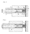
- protrusion to be molded on the injection molded part is shaped such that it or surfaces on it exert a force on corresponding surfaces of the jaws of the segments when the molded part is withdrawn after sufficient solidification, can be according to FIGS. 3 and 4 to a positive control by a control bead 16 and a control sleeve 10 is therefore also dispensed with in the case of an additional part to be installed subsequently.
- the flange 21 of the connecting piece 22 is shaped such that its inner surface 23 exerts a force which expands the mold jaws 26 in the direction of arrow C during a relative movement between the molded part 24 and the sliding pin 25, as a result of which the directly in the outer sleeve 27 - or swivel the segments 29 housed directly in the bore 28 around the holding bead 30 and release the molded connection piece 22.
- die-cast parts according to the invention can also be combined to form a block, it being possible to form a block both by positive control according to FIGS. 1 and 2 and also automatically demoldable parts according to FIGS. 3 and 4.
- the mold accessories for two nozzles lying close together in one plane and for two further lower-lying nozzles are combined in one block.
- the die-cast parts according to the invention can also be easily introduced into existing molds, i.e. Existing towers can be easily converted if one has to attach one or more nozzles to the plastic part to be molded by them or the sliders in the mold have not proven themselves.
Landscapes
- Engineering & Computer Science (AREA)
- Mechanical Engineering (AREA)
- Manufacturing & Machinery (AREA)
- Moulds For Moulding Plastics Or The Like (AREA)
- Molds, Cores, And Manufacturing Methods Thereof (AREA)
Applications Claiming Priority (4)
| Application Number | Priority Date | Filing Date | Title |
|---|---|---|---|
| DE8911864U DE8911864U1 (de) | 1989-10-05 | 1989-10-05 | Druckgussformzusatzteil |
| DE8911864U | 1989-10-05 | ||
| DE4011784 | 1990-04-12 | ||
| DE4011784A DE4011784C2 (de) | 1989-10-05 | 1990-04-12 | Formwerkzeug |
Publications (3)
| Publication Number | Publication Date |
|---|---|
| EP0421136A2 true EP0421136A2 (fr) | 1991-04-10 |
| EP0421136A3 EP0421136A3 (en) | 1991-10-23 |
| EP0421136B1 EP0421136B1 (fr) | 1994-03-02 |
Family
ID=25892127
Family Applications (1)
| Application Number | Title | Priority Date | Filing Date |
|---|---|---|---|
| EP90117053A Expired - Lifetime EP0421136B1 (fr) | 1989-10-05 | 1990-09-05 | Moule d'injection |
Country Status (4)
| Country | Link |
|---|---|
| US (1) | US5090888A (fr) |
| EP (1) | EP0421136B1 (fr) |
| DE (1) | DE4011784C2 (fr) |
| ES (1) | ES2050901T3 (fr) |
Cited By (3)
| Publication number | Priority date | Publication date | Assignee | Title |
|---|---|---|---|---|
| EP0825009A1 (fr) * | 1996-08-21 | 1998-02-25 | Schöttli Ag | Moule d'injection pour fabriquer des fermetures à vis |
| WO2010098874A2 (fr) | 2009-02-27 | 2010-09-02 | Progressive Components International Corporation | Cavité expansible pour outil de moulage par injection |
| DE102012021886B3 (de) * | 2012-11-07 | 2013-11-14 | Audi Ag | Druckgießwerkzeug mit Schieber und darin integriertem Nachverdichter und gemeinsamen Antrieb für Schieber und Nachverdichter |
Families Citing this family (15)
| Publication number | Priority date | Publication date | Assignee | Title |
|---|---|---|---|---|
| US5387389A (en) * | 1993-12-23 | 1995-02-07 | Roehr Tool Corporation | Injection molding method and system with expandable cavity element |
| USD356320S (en) | 1993-12-10 | 1995-03-14 | Roehr Tool Corporation | Expandable core element for use with an injection molding system |
| US5540582A (en) * | 1993-12-10 | 1996-07-30 | Roehr Tool Corporation | Expandable cavity core element for use in an injection molding system |
| DE29513203U1 (de) * | 1995-08-17 | 1996-12-12 | Strack-Norma GmbH, 42117 Wuppertal | Spritzgießwerkzeug |
| ES2156516B1 (es) * | 1998-12-28 | 2002-02-16 | Pruna Alberto Navarra | Expulsor expansible para moldes de inyeccion. |
| US20110151049A1 (en) * | 2006-11-01 | 2011-06-23 | Mueller Hans | Device at a Collapsible Core, Preferably at Injection-Moulding Tool for Plastic Material, Silicone, Rubber and Similar Material |
| US7530807B2 (en) * | 2007-01-30 | 2009-05-12 | Yu-Pei Ho | Mold structure with an ejecting tube for ejecting a molded product and permitting airflow |
| US7981347B2 (en) * | 2008-10-28 | 2011-07-19 | The Procter And Gamble Company | Carrier mold |
| US7740787B2 (en) * | 2008-10-28 | 2010-06-22 | The Procter & Gamble Company | Flexible carrier mold |
| US8033810B2 (en) * | 2009-06-17 | 2011-10-11 | Progressive Components International Corporation | Lock for core assembly for injection molding tool |
| JP5506603B2 (ja) * | 2010-08-27 | 2014-05-28 | 株式会社ショーワ | 金型装置 |
| EP2925467B1 (fr) * | 2012-11-29 | 2018-08-29 | Metallfabriken Ljunghäll AB | Procédé de fabrication d'un article à parois minces en métal |
| WO2016131994A1 (fr) * | 2015-02-18 | 2016-08-25 | Sna Europe Industries Iberia, S.A. | Moule, pièce, système et procédé pour objets à fentes ou cavités |
| JP6836774B2 (ja) * | 2016-11-28 | 2021-03-03 | 株式会社テクノクラーツ | アンダーカット処理機構、成形用金型 |
| CN110744030B (zh) * | 2019-11-05 | 2021-10-19 | 杭州杭富锅炉成套设备有限公司 | 一种锅炉管道小半径的制作方法 |
Family Cites Families (12)
| Publication number | Priority date | Publication date | Assignee | Title |
|---|---|---|---|---|
| FR889742A (fr) * | 1940-06-08 | 1944-01-18 | Moule divisé pour la coulée par injection (coulée sous pression) d'objets moulés présentant des évidements postérieurs | |
| US3618170A (en) * | 1969-07-14 | 1971-11-09 | Edward W Owens | Apparatus for molding plastic closures |
| US3642417A (en) * | 1970-04-29 | 1972-02-15 | Holdt J W Von | Release apparatus for diecasting assembly |
| GB1422705A (en) * | 1972-02-01 | 1976-01-28 | Tupperware Australia Pty Ltd | Moulding apparatus |
| DE2612151A1 (de) * | 1976-03-23 | 1977-10-06 | Formenbau Und Plastik Gmbh | Formeinsatz fuer ein spritzgusswerkzeug |
| US4130264A (en) * | 1977-10-26 | 1978-12-19 | Geyer & Co. | Expandable core for injection molding |
| US4456214A (en) * | 1981-04-06 | 1984-06-26 | Roehr Tool Corporation | Molding apparatus with positive collapse core |
| US4412806A (en) * | 1981-05-15 | 1983-11-01 | The Broadway Companies, Inc. | Parison ejector for an injection molding apparatus |
| JPS59150715A (ja) * | 1983-02-16 | 1984-08-29 | Daiichi Gaiyaa Kk | 金型部材 |
| AR245671A1 (es) * | 1984-08-15 | 1994-02-28 | American Safety Closure | Perfeccionamientos en tapones de material plastico a prueba de manipulaciones indebidas. |
| EP0218345B1 (fr) * | 1985-08-30 | 1989-10-11 | R. Clarke & Co. (Moulds) Limited | Noyau de moule démontable |
| US4956142A (en) * | 1989-05-08 | 1990-09-11 | Mangone Peter G Jr | Apparatus and method for molding three dimensional articles |
-
1990
- 1990-04-12 DE DE4011784A patent/DE4011784C2/de not_active Expired - Fee Related
- 1990-09-05 EP EP90117053A patent/EP0421136B1/fr not_active Expired - Lifetime
- 1990-09-05 ES ES90117053T patent/ES2050901T3/es not_active Expired - Lifetime
- 1990-10-05 US US07/593,857 patent/US5090888A/en not_active Expired - Lifetime
Cited By (4)
| Publication number | Priority date | Publication date | Assignee | Title |
|---|---|---|---|---|
| EP0825009A1 (fr) * | 1996-08-21 | 1998-02-25 | Schöttli Ag | Moule d'injection pour fabriquer des fermetures à vis |
| WO2010098874A2 (fr) | 2009-02-27 | 2010-09-02 | Progressive Components International Corporation | Cavité expansible pour outil de moulage par injection |
| EP2401125A4 (fr) * | 2009-02-27 | 2015-09-02 | Progressive Components Int | Cavité expansible pour outil de moulage par injection |
| DE102012021886B3 (de) * | 2012-11-07 | 2013-11-14 | Audi Ag | Druckgießwerkzeug mit Schieber und darin integriertem Nachverdichter und gemeinsamen Antrieb für Schieber und Nachverdichter |
Also Published As
| Publication number | Publication date |
|---|---|
| DE4011784C2 (de) | 1993-12-23 |
| ES2050901T3 (es) | 1994-06-01 |
| US5090888A (en) | 1992-02-25 |
| EP0421136A3 (en) | 1991-10-23 |
| EP0421136B1 (fr) | 1994-03-02 |
| DE4011784A1 (de) | 1991-04-18 |
Similar Documents
| Publication | Publication Date | Title |
|---|---|---|
| EP0421136B1 (fr) | Moule d'injection | |
| DE3346228C2 (de) | Gießform mit zusammenklappbarem Kern | |
| DE2327269B2 (de) | Vorrichtung zum zuleiten eines insbesondere chemisch reaktionsfaehigen kunststoffgemisches zu einer form | |
| CH643047A5 (de) | Verfahren zum herstellen von fittings fuer rohrverbindungen sowie werkzeug zur ausuebung des verfahrens und nach diesem verfahren hergestelltes fitting. | |
| DE3616037A1 (de) | Giessform | |
| EP0966624A1 (fr) | Element de protection pliant pour lignes | |
| DE69012052T2 (de) | Rohrförmiges Element zur Abdichtung einer hin- und herbewegten Stange. | |
| DE2619064C3 (de) | Formkern zum Herstellen von Spritzteilen | |
| EP0100422B1 (fr) | Moule d'injection | |
| DE69220357T2 (de) | Verfahren zum Formen eines Ansaugrohrs für Kraftfahrzeuge | |
| DE69311644T2 (de) | Vorrichtung und Verfahren zum Schmieden eines schrägverzahnten Zahnrades | |
| DE3134602A1 (de) | "verfahren zur herstellung einer tube aus kunststoff und vorrichtung zur durchfuehrung desselben" | |
| DE60018877T2 (de) | Verriegelungshalter für Schnellkupplungen mit ausgesparter Sperrklinke | |
| DE3227276C2 (de) | Vorrichtung zur Herstellung einer Kette imn Gießverfahren | |
| EP1636473B2 (fr) | Piston pour un moteur a combustion interne et procede de coulee pour sa production | |
| WO2000072116A2 (fr) | Procede de production d'un piston en forme de caisson | |
| DE69128415T2 (de) | Formen für horizontal/vertikal druckgussmaschinen | |
| DE134144T1 (de) | Verfahren und einrichtung zur herstellung eines gegenstandes mit innengewinde. | |
| DE19513693C1 (de) | Verfahren und Vorrichtung zur Herstellung eines Kugelgelenkes | |
| DE9414523U1 (de) | Spritzgießform | |
| EP0484315A2 (fr) | Moule d'injection | |
| DE2156273A1 (de) | Spritzgussform zur herstellung von reissverschlusschiebern | |
| DE19752786A1 (de) | Verfahren zur Herstellung von Ablagefächern | |
| DE102012208563A1 (de) | Einfallkern | |
| DE8911864U1 (de) | Druckgussformzusatzteil |
Legal Events
| Date | Code | Title | Description |
|---|---|---|---|
| PUAI | Public reference made under article 153(3) epc to a published international application that has entered the european phase |
Free format text: ORIGINAL CODE: 0009012 |
|
| AK | Designated contracting states |
Kind code of ref document: A2 Designated state(s): ES FR GB IT |
|
| PUAL | Search report despatched |
Free format text: ORIGINAL CODE: 0009013 |
|
| AK | Designated contracting states |
Kind code of ref document: A3 Designated state(s): ES FR GB IT |
|
| 17P | Request for examination filed |
Effective date: 19920416 |
|
| 17Q | First examination report despatched |
Effective date: 19920916 |
|
| GRAA | (expected) grant |
Free format text: ORIGINAL CODE: 0009210 |
|
| AK | Designated contracting states |
Kind code of ref document: B1 Designated state(s): ES FR GB IT |
|
| GBT | Gb: translation of ep patent filed (gb section 77(6)(a)/1977) |
Effective date: 19940323 |
|
| ITF | It: translation for a ep patent filed | ||
| ET | Fr: translation filed | ||
| REG | Reference to a national code |
Ref country code: ES Ref legal event code: FG2A Ref document number: 2050901 Country of ref document: ES Kind code of ref document: T3 |
|
| PLBE | No opposition filed within time limit |
Free format text: ORIGINAL CODE: 0009261 |
|
| STAA | Information on the status of an ep patent application or granted ep patent |
Free format text: STATUS: NO OPPOSITION FILED WITHIN TIME LIMIT |
|
| 26N | No opposition filed | ||
| REG | Reference to a national code |
Ref country code: GB Ref legal event code: IF02 |
|
| PGFP | Annual fee paid to national office [announced via postgrant information from national office to epo] |
Ref country code: FR Payment date: 20050822 Year of fee payment: 16 |
|
| PGFP | Annual fee paid to national office [announced via postgrant information from national office to epo] |
Ref country code: ES Payment date: 20050830 Year of fee payment: 16 |
|
| PGFP | Annual fee paid to national office [announced via postgrant information from national office to epo] |
Ref country code: GB Payment date: 20050831 Year of fee payment: 16 |
|
| PGFP | Annual fee paid to national office [announced via postgrant information from national office to epo] |
Ref country code: IT Payment date: 20060930 Year of fee payment: 17 |
|
| GBPC | Gb: european patent ceased through non-payment of renewal fee |
Effective date: 20060905 |
|
| REG | Reference to a national code |
Ref country code: FR Ref legal event code: ST Effective date: 20070531 |
|
| PG25 | Lapsed in a contracting state [announced via postgrant information from national office to epo] |
Ref country code: GB Free format text: LAPSE BECAUSE OF NON-PAYMENT OF DUE FEES Effective date: 20060905 |
|
| REG | Reference to a national code |
Ref country code: ES Ref legal event code: FD2A Effective date: 20060906 |
|
| PG25 | Lapsed in a contracting state [announced via postgrant information from national office to epo] |
Ref country code: ES Free format text: LAPSE BECAUSE OF NON-PAYMENT OF DUE FEES Effective date: 20060906 |
|
| PG25 | Lapsed in a contracting state [announced via postgrant information from national office to epo] |
Ref country code: FR Free format text: LAPSE BECAUSE OF NON-PAYMENT OF DUE FEES Effective date: 20061002 |
|
| PG25 | Lapsed in a contracting state [announced via postgrant information from national office to epo] |
Ref country code: IT Free format text: LAPSE BECAUSE OF NON-PAYMENT OF DUE FEES Effective date: 20070905 |