EP0421171A1 - Radbefestigung für ein Regalförderzeug - Google Patents
Radbefestigung für ein Regalförderzeug Download PDFInfo
- Publication number
- EP0421171A1 EP0421171A1 EP90117775A EP90117775A EP0421171A1 EP 0421171 A1 EP0421171 A1 EP 0421171A1 EP 90117775 A EP90117775 A EP 90117775A EP 90117775 A EP90117775 A EP 90117775A EP 0421171 A1 EP0421171 A1 EP 0421171A1
- Authority
- EP
- European Patent Office
- Prior art keywords
- mounting member
- wheel
- plate
- base
- mounting
- Prior art date
- Legal status (The legal status is an assumption and is not a legal conclusion. Google has not performed a legal analysis and makes no representation as to the accuracy of the status listed.)
- Granted
Links
- 238000010348 incorporation Methods 0.000 description 1
- 238000012423 maintenance Methods 0.000 description 1
- 239000002184 metal Substances 0.000 description 1
- 238000000034 method Methods 0.000 description 1
- 230000000737 periodic effect Effects 0.000 description 1
- 239000007787 solid Substances 0.000 description 1
- 239000003351 stiffener Substances 0.000 description 1
Images


Classifications
-
- B—PERFORMING OPERATIONS; TRANSPORTING
- B66—HOISTING; LIFTING; HAULING
- B66F—HOISTING, LIFTING, HAULING OR PUSHING, NOT OTHERWISE PROVIDED FOR, e.g. DEVICES WHICH APPLY A LIFTING OR PUSHING FORCE DIRECTLY TO THE SURFACE OF A LOAD
- B66F9/00—Devices for lifting or lowering bulky or heavy goods for loading or unloading purposes
- B66F9/06—Devices for lifting or lowering bulky or heavy goods for loading or unloading purposes movable, with their loads, on wheels or the like, e.g. fork-lift trucks
- B66F9/07—Floor-to-roof stacking devices, e.g. "stacker cranes", "retrievers"
-
- B—PERFORMING OPERATIONS; TRANSPORTING
- B66—HOISTING; LIFTING; HAULING
- B66F—HOISTING, LIFTING, HAULING OR PUSHING, NOT OTHERWISE PROVIDED FOR, e.g. DEVICES WHICH APPLY A LIFTING OR PUSHING FORCE DIRECTLY TO THE SURFACE OF A LOAD
- B66F9/00—Devices for lifting or lowering bulky or heavy goods for loading or unloading purposes
- B66F9/06—Devices for lifting or lowering bulky or heavy goods for loading or unloading purposes movable, with their loads, on wheels or the like, e.g. fork-lift trucks
- B66F9/07—Floor-to-roof stacking devices, e.g. "stacker cranes", "retrievers"
- B66F9/072—Travelling gear therefor
Definitions
- the present invention relates to storage and retrieval (S/R) machines, and more particularly to apparatus for mounting the drive and idler wheels of such machines.
- a typical storage and retrieval machine travels on a single floor-mounted rail in an aisle between rows of storage racks.
- the machine comprises a base member, and a vertical mast secured to the base, which mast can be as tall as 100 ft. or more.
- the base member is supported on the rail by a drive wheel at one end of the base member and an idler wheel at the other end.
- the machine is stabilized by guide wheels at the top of the mast which engage an overhead rail.
- the present invention provides a simple, yet effective apparatus for mounting and aligning the drive and idler wheels of an S/R machine. More specifically, the invention provides a wheel mounting module attached to the machine which provides a spherical interface between the base and the wheel and means for manipulating the interfaced members to provide simple and accurate alignment therebetween.
- the wheel is supported by pillow blocks fixed to a domed plate which interfits with a spherical concave surface formed in a cap member attached to the frame of the module.
- the relative positions of the spherical members is adjusted by means of jackscrews to align the wheel both vertically and longitudinally with respect to the supporting rail. After the alignment is completed the dome and cap are clamped together by means of angularly mounted lock screws.
- an S/R machine 10 comprising a base assembly 12, a drive wheel 14 mounted for rotation on the frame 12 and engageable with a floor supported rail 16, an idler wheel 18 mounted for rotation on the frame and engageable with the rail 16, a drive motor assembly 20 mounted on the frame and operatively connected to the drive wheel to drive the S/R machine along the rail, a mast assembly 22 mounted to the frame, a load carriage assembly 24 mounted to the mast assembly for vertical movement, and a vertical drive assembly 26 mounted on the frame and operable to drive the load carriage up and down the mast by means of a cable system 28.
- the vehicle is stabilized by means of horizontal guide wheels 29 which engage an overhead rail 30.
- the drive wheel 14 and the idler wheel 18 are mounted on modules 32 and 34 respectively which are bolted or otherwise removably attached to the base assembly 12. Except for the incorporation of the drive motor assembly into the drive wheel module 32, the drive wheel module and the idler wheel module 34 are essentially identical, and only the idler wheel module will be described in detail herein.
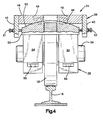
- the idler wheel module 34 comprises a frame 36 which is bolted to the base 12, and a wheel assembly 38 which is adjustably mounted on the frame 36.
- the frame 36 comprises a pair of side plates 42 and 43, a pair of transverse angle members 44 and 45 welded to the side plates, a mounting plate 46, which is welded to the side plates and to which the wheel assembly is attached, and a plurality of stiffeners 47 welded to the angle members.
- the mounting plate 46 comprises a solid metal plate having a concave spherical surface 48 formed in the underside thereof, and having four counterbored holes 49 formed therein and extending radially through the spherical surface.
- the wheel assembly 38 comprises a plate 50 having a convex spherical surface 52 formed thereon, a pair of pillow blocks 54 attached to the plate 50 by means of bolts 55, an axle 56 received for rotation in the pillow blocks, and wheel 18 fixed to the axle.
- the center area of the plate 50 is relieved in a series of steps, indicated typically by the broken lines 51 in Fig. 3 to provide clearance for the wheel 18.
- the convex surface 52 of the plate 50 and the concave surface 48 of the plate 46 interfit to form a spherical joint, with the plate 46 maintained in a fixed position, and the plate 50 free to rotate in any direction about the centerpoint of the spherical surfaces.
- the wheel assembly 38 is attached to the mounting plate 46 by means of four screws 58 which are received through the holes 49 and threaded into holes formed in the plate 50, the holes 49 being oversize to permit limited movement of the plate 50 with respect to the plate 46 prior to tightening the screws.
- Alignment of the wheel assembly 38 with the rail 16 is effected by means of jackscrews 60 and 61 which are threaded through side plate 42 and bear against one side of plate 50, and jackscrews 62 and 63 which are threaded through side plate 43 and bear against the opposite side of plate 50.
- the jackscrews are alternately tightened and loosened diagonally, that is screw 60 against screw 63 and screw 61 against screw 62 to rotate the plate 50 about an axis perpendicular to the surface of the rail.
- jackscrews 60 and 61 are tightened or loosened together against jackscrews 62 and 63 to rotate the plate 50 about an axis parallel to the surface of the rail.
- the jackscrews are locked by means of nuts 64 received between the heads of the jackscrews and the plates 42 and 43 and the screws 58 are tightened to clamp plates 46 and 50 together.
- modules 32 and 34 are easily accessible for adjustment when the vehicle 10 is initially erected in the field and for periodic readjustment as required.
Landscapes
- Engineering & Computer Science (AREA)
- Transportation (AREA)
- Structural Engineering (AREA)
- Civil Engineering (AREA)
- Life Sciences & Earth Sciences (AREA)
- Geology (AREA)
- Mechanical Engineering (AREA)
- Warehouses Or Storage Devices (AREA)
- Forklifts And Lifting Vehicles (AREA)
- Platform Screen Doors And Railroad Systems (AREA)
- Handcart (AREA)
- Carriers, Traveling Bodies, And Overhead Traveling Cranes (AREA)
- Body Structure For Vehicles (AREA)
- Machines For Laying And Maintaining Railways (AREA)
- Catching Or Destruction (AREA)
- Table Equipment (AREA)
- Clamps And Clips (AREA)
- Pallets (AREA)
- Automobile Manufacture Line, Endless Track Vehicle, Trailer (AREA)
- Fittings On The Vehicle Exterior For Carrying Loads, And Devices For Holding Or Mounting Articles (AREA)
Priority Applications (1)
| Application Number | Priority Date | Filing Date | Title |
|---|---|---|---|
| AT90117775T ATE92433T1 (de) | 1989-10-02 | 1990-09-15 | Radbefestigung fuer ein regalfoerderzeug. |
Applications Claiming Priority (2)
| Application Number | Priority Date | Filing Date | Title |
|---|---|---|---|
| US415738 | 1989-10-02 | ||
| US07/415,738 US5005912A (en) | 1989-10-02 | 1989-10-02 | Wheel mounting assembly for a storage and retrieval machine |
Publications (2)
| Publication Number | Publication Date |
|---|---|
| EP0421171A1 true EP0421171A1 (de) | 1991-04-10 |
| EP0421171B1 EP0421171B1 (de) | 1993-08-04 |
Family
ID=23646983
Family Applications (1)
| Application Number | Title | Priority Date | Filing Date |
|---|---|---|---|
| EP90117775A Expired - Lifetime EP0421171B1 (de) | 1989-10-02 | 1990-09-15 | Radbefestigung für ein Regalförderzeug |
Country Status (9)
| Country | Link |
|---|---|
| US (1) | US5005912A (de) |
| EP (1) | EP0421171B1 (de) |
| JP (1) | JPH03133898A (de) |
| KR (1) | KR960005309B1 (de) |
| AT (1) | ATE92433T1 (de) |
| AU (1) | AU636088B2 (de) |
| CA (1) | CA2024559C (de) |
| DE (1) | DE69002573T2 (de) |
| ES (1) | ES2043208T3 (de) |
Cited By (2)
| Publication number | Priority date | Publication date | Assignee | Title |
|---|---|---|---|---|
| CN104477820A (zh) * | 2014-12-03 | 2015-04-01 | 无锡中鼎物流设备有限公司 | 一种用于堆垛机的水平导向轮组支架 |
| CN106185621A (zh) * | 2016-07-27 | 2016-12-07 | 河南省鑫源起重机有限公司 | 一种起重机小车防啃轨系统 |
Families Citing this family (11)
| Publication number | Priority date | Publication date | Assignee | Title |
|---|---|---|---|---|
| US5020957A (en) * | 1989-12-21 | 1991-06-04 | Eaton-Kenway, Inc. | Mast to base connection for a storage and retrieval machine |
| DE4031685C3 (de) * | 1990-10-04 | 2001-11-08 | Mannesmann Ag | Laufradblock |
| US5170713A (en) * | 1990-10-09 | 1992-12-15 | Harnischfeger Engineers | Wheel assembly for a storage and retrieval machine |
| US5433292A (en) * | 1993-08-26 | 1995-07-18 | Hk Systems, Inc. | Stacker |
| US5943960A (en) * | 1995-10-18 | 1999-08-31 | Mannesmann Ag | Running wheel block |
| US6681702B1 (en) | 2002-04-12 | 2004-01-27 | Charles W. Nicely | Skate for use with a floor track storage system |
| DE102011002044A1 (de) * | 2011-04-14 | 2012-10-18 | Demag Cranes & Components Gmbh | Anordnung und Verfahren zur Ausrichtung eines Laufradblocks |
| CN102491169B (zh) * | 2011-12-21 | 2014-05-21 | 三一集团有限公司 | 行走纠偏装置及应用该装置的轨道式工程机械 |
| US9937549B2 (en) | 2014-07-09 | 2018-04-10 | The Boeing Company | Two-stage riveting |
| CN106594055B (zh) * | 2015-10-15 | 2019-05-21 | 中国航空工业集团公司北京航空精密机械研究所 | 一种锥形滚轮驱动轮组 |
| US10364107B2 (en) * | 2016-05-27 | 2019-07-30 | Richmond Engineering Works L.L.C. | Trunnion assembly for rotary dumper |
Citations (4)
| Publication number | Priority date | Publication date | Assignee | Title |
|---|---|---|---|---|
| DE881209C (de) * | 1951-06-19 | 1953-06-29 | Krauss Maffei Ag | Achslager mit im Lagergehaeuse angeordnetem Waelzlager fuer Schienenfahrzeuge, insbesondere fuer Lokomotiven |
| DE1213971B (de) * | 1960-11-24 | 1966-04-07 | Demag Ag | Kranlaufradlagerung mit in den beiden Stegblechen des Kranlaufradtraegers gelagertemLaufradlagerbolzen |
| DE8201259U1 (de) * | 1982-01-21 | 1983-04-07 | Albert Vogelsang GmbH & Co, 5270 Gummersbach | Regalbedienungsgeraet |
| GB2188378A (en) * | 1986-03-27 | 1987-09-30 | Mannesmann Ag | Adjustable bearing of a crane runner wheel |
Family Cites Families (3)
| Publication number | Priority date | Publication date | Assignee | Title |
|---|---|---|---|---|
| US1007472A (en) * | 1909-07-20 | 1911-10-31 | J S Andrews Company | Car-truck. |
| US1376684A (en) * | 1920-09-03 | 1921-05-03 | Scullin Steel Co | Railway side-frame and journal-box connection |
| GB970631A (en) * | 1962-03-21 | 1964-09-23 | Arthur Paul Pedrick | Air film bearings,particularly for railway vehicles |
-
1989
- 1989-10-02 US US07/415,738 patent/US5005912A/en not_active Expired - Lifetime
-
1990
- 1990-09-04 CA CA002024559A patent/CA2024559C/en not_active Expired - Fee Related
- 1990-09-05 AU AU62148/90A patent/AU636088B2/en not_active Ceased
- 1990-09-06 KR KR1019900014063A patent/KR960005309B1/ko not_active Expired - Lifetime
- 1990-09-15 AT AT90117775T patent/ATE92433T1/de not_active IP Right Cessation
- 1990-09-15 ES ES90117775T patent/ES2043208T3/es not_active Expired - Lifetime
- 1990-09-15 EP EP90117775A patent/EP0421171B1/de not_active Expired - Lifetime
- 1990-09-15 DE DE90117775T patent/DE69002573T2/de not_active Expired - Fee Related
- 1990-09-26 JP JP2256804A patent/JPH03133898A/ja active Pending
Patent Citations (4)
| Publication number | Priority date | Publication date | Assignee | Title |
|---|---|---|---|---|
| DE881209C (de) * | 1951-06-19 | 1953-06-29 | Krauss Maffei Ag | Achslager mit im Lagergehaeuse angeordnetem Waelzlager fuer Schienenfahrzeuge, insbesondere fuer Lokomotiven |
| DE1213971B (de) * | 1960-11-24 | 1966-04-07 | Demag Ag | Kranlaufradlagerung mit in den beiden Stegblechen des Kranlaufradtraegers gelagertemLaufradlagerbolzen |
| DE8201259U1 (de) * | 1982-01-21 | 1983-04-07 | Albert Vogelsang GmbH & Co, 5270 Gummersbach | Regalbedienungsgeraet |
| GB2188378A (en) * | 1986-03-27 | 1987-09-30 | Mannesmann Ag | Adjustable bearing of a crane runner wheel |
Cited By (4)
| Publication number | Priority date | Publication date | Assignee | Title |
|---|---|---|---|---|
| CN104477820A (zh) * | 2014-12-03 | 2015-04-01 | 无锡中鼎物流设备有限公司 | 一种用于堆垛机的水平导向轮组支架 |
| CN104477820B (zh) * | 2014-12-03 | 2017-07-21 | 无锡中鼎集成技术有限公司 | 一种用于堆垛机的水平导向轮组支架 |
| CN106185621A (zh) * | 2016-07-27 | 2016-12-07 | 河南省鑫源起重机有限公司 | 一种起重机小车防啃轨系统 |
| CN106185621B (zh) * | 2016-07-27 | 2018-06-01 | 河南省鑫源起重机有限公司 | 一种起重机小车防啃轨系统 |
Also Published As
| Publication number | Publication date |
|---|---|
| ATE92433T1 (de) | 1993-08-15 |
| DE69002573T2 (de) | 1993-11-25 |
| CA2024559C (en) | 1998-05-19 |
| CA2024559A1 (en) | 1991-04-03 |
| EP0421171B1 (de) | 1993-08-04 |
| DE69002573D1 (de) | 1993-09-09 |
| KR910007744A (ko) | 1991-05-30 |
| US5005912A (en) | 1991-04-09 |
| KR960005309B1 (ko) | 1996-04-23 |
| AU636088B2 (en) | 1993-04-08 |
| ES2043208T3 (es) | 1993-12-16 |
| AU6214890A (en) | 1991-04-11 |
| JPH03133898A (ja) | 1991-06-07 |
Similar Documents
| Publication | Publication Date | Title |
|---|---|---|
| US5005912A (en) | Wheel mounting assembly for a storage and retrieval machine | |
| JP2653982B2 (ja) | 案内レールの取り付け方法 | |
| US4603570A (en) | Universal dedicated fixture for frame straightening rack | |
| WO2025039650A1 (zh) | 一种单轨列车转向架构架装夹装置及构架加工方法 | |
| CN222404186U (zh) | 一种分体式系杆焊设备 | |
| US5016407A (en) | Robot conveyor system | |
| CN220388475U (zh) | 一种定位设备及激光焊接设备 | |
| CA1288750C (en) | Adjustable height, self centering vertically stabilized and lockable clamp stand | |
| CN218597793U (zh) | 一种自适应同步驱动机构 | |
| CN218666956U (zh) | 轨排精调车及轨排精调设备 | |
| CN118989628A (zh) | 一种大尺寸型钢激光切割设备 | |
| CN113146514B (zh) | 一种具有防窜动功能的可调节滚轮架 | |
| CN222986212U (zh) | 一种自动翻转螺栓锁付装置 | |
| CN218800096U (zh) | 一种焊接工装设备 | |
| US4372426A (en) | Mast structure | |
| CN222608728U (zh) | 连接组件、支撑模组、床身及加工设备 | |
| CN119526058B (zh) | 一种铰孔夹具 | |
| CN216990758U (zh) | 心盘螺栓自动紧固装置 | |
| CN115284020B (zh) | 机床固定基座 | |
| CN220745278U (zh) | 一种双立柱堆垛机的可调平衡立柱结构 | |
| CN223686620U (zh) | 核电厂管道防旋转装置 | |
| CN118123758B (zh) | 一种钢网架螺栓智能紧固装置 | |
| CN117464590B (zh) | 地铁转向架构架定位设备及定位方法 | |
| CN222307818U (zh) | 一种机柜焊接装夹治具 | |
| CN222837604U (zh) | 一种编码器固定装置 |
Legal Events
| Date | Code | Title | Description |
|---|---|---|---|
| PUAI | Public reference made under article 153(3) epc to a published international application that has entered the european phase |
Free format text: ORIGINAL CODE: 0009012 |
|
| AK | Designated contracting states |
Kind code of ref document: A1 Designated state(s): AT BE CH DE ES FR GB IT LI LU NL SE |
|
| 17P | Request for examination filed |
Effective date: 19910326 |
|
| 17Q | First examination report despatched |
Effective date: 19910702 |
|
| GRAA | (expected) grant |
Free format text: ORIGINAL CODE: 0009210 |
|
| AK | Designated contracting states |
Kind code of ref document: B1 Designated state(s): AT BE CH DE ES FR GB IT LI LU NL SE |
|
| REF | Corresponds to: |
Ref document number: 92433 Country of ref document: AT Date of ref document: 19930815 Kind code of ref document: T |
|
| ITF | It: translation for a ep patent filed | ||
| REF | Corresponds to: |
Ref document number: 69002573 Country of ref document: DE Date of ref document: 19930909 |
|
| ET | Fr: translation filed | ||
| REG | Reference to a national code |
Ref country code: ES Ref legal event code: FG2A Ref document number: 2043208 Country of ref document: ES Kind code of ref document: T3 |
|
| PLBE | No opposition filed within time limit |
Free format text: ORIGINAL CODE: 0009261 |
|
| STAA | Information on the status of an ep patent application or granted ep patent |
Free format text: STATUS: NO OPPOSITION FILED WITHIN TIME LIMIT |
|
| 26N | No opposition filed | ||
| PGFP | Annual fee paid to national office [announced via postgrant information from national office to epo] |
Ref country code: LU Payment date: 19940731 Year of fee payment: 5 |
|
| PGFP | Annual fee paid to national office [announced via postgrant information from national office to epo] |
Ref country code: GB Payment date: 19940810 Year of fee payment: 5 |
|
| PGFP | Annual fee paid to national office [announced via postgrant information from national office to epo] |
Ref country code: AT Payment date: 19940823 Year of fee payment: 5 |
|
| PGFP | Annual fee paid to national office [announced via postgrant information from national office to epo] |
Ref country code: SE Payment date: 19940824 Year of fee payment: 5 |
|
| PGFP | Annual fee paid to national office [announced via postgrant information from national office to epo] |
Ref country code: FR Payment date: 19940908 Year of fee payment: 5 |
|
| PGFP | Annual fee paid to national office [announced via postgrant information from national office to epo] |
Ref country code: ES Payment date: 19940912 Year of fee payment: 5 |
|
| PGFP | Annual fee paid to national office [announced via postgrant information from national office to epo] |
Ref country code: BE Payment date: 19940928 Year of fee payment: 5 |
|
| PGFP | Annual fee paid to national office [announced via postgrant information from national office to epo] |
Ref country code: DE Payment date: 19940929 Year of fee payment: 5 |
|
| PGFP | Annual fee paid to national office [announced via postgrant information from national office to epo] |
Ref country code: NL Payment date: 19940930 Year of fee payment: 5 |
|
| EPTA | Lu: last paid annual fee | ||
| PGFP | Annual fee paid to national office [announced via postgrant information from national office to epo] |
Ref country code: CH Payment date: 19941018 Year of fee payment: 5 |
|
| EAL | Se: european patent in force in sweden |
Ref document number: 90117775.8 |
|
| PG25 | Lapsed in a contracting state [announced via postgrant information from national office to epo] |
Ref country code: LU Free format text: LAPSE BECAUSE OF NON-PAYMENT OF DUE FEES Effective date: 19950915 Ref country code: GB Effective date: 19950915 Ref country code: AT Effective date: 19950915 |
|
| PG25 | Lapsed in a contracting state [announced via postgrant information from national office to epo] |
Ref country code: SE Effective date: 19950916 Ref country code: ES Free format text: LAPSE BECAUSE OF THE APPLICANT RENOUNCES Effective date: 19950916 |
|
| PG25 | Lapsed in a contracting state [announced via postgrant information from national office to epo] |
Ref country code: LI Effective date: 19950930 Ref country code: CH Effective date: 19950930 Ref country code: BE Effective date: 19950930 |
|
| BERE | Be: lapsed |
Owner name: EATON-KENWAY INC. Effective date: 19950930 |
|
| PG25 | Lapsed in a contracting state [announced via postgrant information from national office to epo] |
Ref country code: NL Effective date: 19960401 |
|
| GBPC | Gb: european patent ceased through non-payment of renewal fee |
Effective date: 19950915 |
|
| REG | Reference to a national code |
Ref country code: CH Ref legal event code: PL |
|
| PG25 | Lapsed in a contracting state [announced via postgrant information from national office to epo] |
Ref country code: FR Effective date: 19960531 |
|
| PG25 | Lapsed in a contracting state [announced via postgrant information from national office to epo] |
Ref country code: DE Effective date: 19960601 |
|
| NLV4 | Nl: lapsed or anulled due to non-payment of the annual fee |
Effective date: 19960401 |
|
| EUG | Se: european patent has lapsed |
Ref document number: 90117775.8 |
|
| REG | Reference to a national code |
Ref country code: FR Ref legal event code: ST |
|
| REG | Reference to a national code |
Ref country code: ES Ref legal event code: FD2A Effective date: 19991007 |
|
| PG25 | Lapsed in a contracting state [announced via postgrant information from national office to epo] |
Ref country code: IT Free format text: LAPSE BECAUSE OF NON-PAYMENT OF DUE FEES;WARNING: LAPSES OF ITALIAN PATENTS WITH EFFECTIVE DATE BEFORE 2007 MAY HAVE OCCURRED AT ANY TIME BEFORE 2007. THE CORRECT EFFECTIVE DATE MAY BE DIFFERENT FROM THE ONE RECORDED. Effective date: 20050915 |