EP0421301A2 - Siège de véhicule - Google Patents
Siège de véhicule Download PDFInfo
- Publication number
- EP0421301A2 EP0421301A2 EP90118698A EP90118698A EP0421301A2 EP 0421301 A2 EP0421301 A2 EP 0421301A2 EP 90118698 A EP90118698 A EP 90118698A EP 90118698 A EP90118698 A EP 90118698A EP 0421301 A2 EP0421301 A2 EP 0421301A2
- Authority
- EP
- European Patent Office
- Prior art keywords
- seat
- lift handle
- base plates
- shaft
- frame
- Prior art date
- Legal status (The legal status is an assumption and is not a legal conclusion. Google has not performed a legal analysis and makes no representation as to the accuracy of the status listed.)
- Withdrawn
Links
Images


Classifications
-
- B—PERFORMING OPERATIONS; TRANSPORTING
- B60—VEHICLES IN GENERAL
- B60N—SEATS SPECIALLY ADAPTED FOR VEHICLES; VEHICLE PASSENGER ACCOMMODATION NOT OTHERWISE PROVIDED FOR
- B60N2/00—Seats specially adapted for vehicles; Arrangement or mounting of seats in vehicles
-
- B—PERFORMING OPERATIONS; TRANSPORTING
- B60—VEHICLES IN GENERAL
- B60N—SEATS SPECIALLY ADAPTED FOR VEHICLES; VEHICLE PASSENGER ACCOMMODATION NOT OTHERWISE PROVIDED FOR
- B60N2/00—Seats specially adapted for vehicles; Arrangement or mounting of seats in vehicles
- B60N2/02—Seats specially adapted for vehicles; Arrangement or mounting of seats in vehicles the seat or part thereof being movable, e.g. adjustable
- B60N2/04—Seats specially adapted for vehicles; Arrangement or mounting of seats in vehicles the seat or part thereof being movable, e.g. adjustable the whole seat being movable
- B60N2/16—Seats specially adapted for vehicles; Arrangement or mounting of seats in vehicles the seat or part thereof being movable, e.g. adjustable the whole seat being movable height-adjustable
- B60N2/18—Seats specially adapted for vehicles; Arrangement or mounting of seats in vehicles the seat or part thereof being movable, e.g. adjustable the whole seat being movable height-adjustable the front or the rear portion of the seat being adjustable, e.g. independently of each other
- B60N2/1803—Seats specially adapted for vehicles; Arrangement or mounting of seats in vehicles the seat or part thereof being movable, e.g. adjustable the whole seat being movable height-adjustable the front or the rear portion of the seat being adjustable, e.g. independently of each other with independent front and/or rear adjustment
-
- B—PERFORMING OPERATIONS; TRANSPORTING
- B60—VEHICLES IN GENERAL
- B60N—SEATS SPECIALLY ADAPTED FOR VEHICLES; VEHICLE PASSENGER ACCOMMODATION NOT OTHERWISE PROVIDED FOR
- B60N2/00—Seats specially adapted for vehicles; Arrangement or mounting of seats in vehicles
- B60N2/02—Seats specially adapted for vehicles; Arrangement or mounting of seats in vehicles the seat or part thereof being movable, e.g. adjustable
- B60N2/04—Seats specially adapted for vehicles; Arrangement or mounting of seats in vehicles the seat or part thereof being movable, e.g. adjustable the whole seat being movable
- B60N2/16—Seats specially adapted for vehicles; Arrangement or mounting of seats in vehicles the seat or part thereof being movable, e.g. adjustable the whole seat being movable height-adjustable
- B60N2/18—Seats specially adapted for vehicles; Arrangement or mounting of seats in vehicles the seat or part thereof being movable, e.g. adjustable the whole seat being movable height-adjustable the front or the rear portion of the seat being adjustable, e.g. independently of each other
- B60N2/1807—Seats specially adapted for vehicles; Arrangement or mounting of seats in vehicles the seat or part thereof being movable, e.g. adjustable the whole seat being movable height-adjustable the front or the rear portion of the seat being adjustable, e.g. independently of each other characterised by the cinematic
- B60N2/181—Rods
-
- B—PERFORMING OPERATIONS; TRANSPORTING
- B60—VEHICLES IN GENERAL
- B60N—SEATS SPECIALLY ADAPTED FOR VEHICLES; VEHICLE PASSENGER ACCOMMODATION NOT OTHERWISE PROVIDED FOR
- B60N2/00—Seats specially adapted for vehicles; Arrangement or mounting of seats in vehicles
- B60N2/02—Seats specially adapted for vehicles; Arrangement or mounting of seats in vehicles the seat or part thereof being movable, e.g. adjustable
- B60N2/04—Seats specially adapted for vehicles; Arrangement or mounting of seats in vehicles the seat or part thereof being movable, e.g. adjustable the whole seat being movable
- B60N2/16—Seats specially adapted for vehicles; Arrangement or mounting of seats in vehicles the seat or part thereof being movable, e.g. adjustable the whole seat being movable height-adjustable
- B60N2/18—Seats specially adapted for vehicles; Arrangement or mounting of seats in vehicles the seat or part thereof being movable, e.g. adjustable the whole seat being movable height-adjustable the front or the rear portion of the seat being adjustable, e.g. independently of each other
- B60N2/185—Seats specially adapted for vehicles; Arrangement or mounting of seats in vehicles the seat or part thereof being movable, e.g. adjustable the whole seat being movable height-adjustable the front or the rear portion of the seat being adjustable, e.g. independently of each other characterised by the drive mechanism
- B60N2/1864—Gear wheel driven mechanism
Definitions
- the present invention relates to a vehicle seat provided with a seat lifting device for adjusting the height of the seat cushion.
- the primary object of the present invention is to provide a vehicle seat provided with a unified seat lifting device so modified as to be readily attachable to the ordinary vehicle seat provided with no such seat lifting device.
- a vehicle seat having: (a) a seat cushion frame (60) for mounting a seat cushion (SC); (b) a pair of seat base plates (40A, 40B) arranged in parallel to each other at an interval; (c) at least one seat lift handle (10); and (d) a seat lifting device (20) actuated by said seat lift handle, for adjustably lifting said seat cushion frame, said at least one seat lift handle and said seat lifting device being assembled into a unit and removably mounted between a pair of said seat base plates.
- the at least one seat lift handle is a seat front lift handle (10A) for adjustably moving up and down a front part of the seat cushion; and said seat lifting device comprises: (a) a pair of mounting frames (22A, 22B) fixed to an inside surface of one (40A) of said seat base plates, for rotatably supporting an axle (24A) of said seat front lift handle (10A); (b) a front pinion gear (25A) rotatably supported between said two mounting frames and fixed to said seat front lift handle coaxially therewith; (c) a front sector gear (26A) rotatably supported between said two mounting frames in mesh with said front pinion gear; (d) a front spring brake mechanism (27A) fixed on an outside surface of said mounting frame coaxially with said seat front lift handle; (e) a front shaft (30A) rotatably supported between said two seat base plates (40A, 40B) under the front part of said seat cushion frame and coaxially with said front sector gear; (f) a front sector gear link (31A)
- the vehicle seat further comprises: (a) a seat rear lift handle (10B) rotatably supported by said mounting frame, for adjustably moving up and down a rear part of the seat cushion; (b) a rear pinion gear (25B) rotatably supported between said two mounting frames and fixed to said seat rear lift handle coaxially therewith; (c) a rear sector gear (26B) rotatably supported between said two mounting frames in mesh with said rear pinion gear; (d) a rear spring brake mechanism (27B) fixed on an outside surface of said mounting frame coaxially with said seat rear lift handle; (e) a rear shaft (30B) rotatably supported between said two seat base plates (40A, 40B) under the rear part of said seat cushion frame; (f) a rear sector gear link (34) for linking said rear sector gear (26B) with said rear shaft (30B); and (g) at least two rear shaft link levers (35, 36) connected between said rear shaft (30B) and said seat cushion frame (60), for moving up and down the rear part
- the mounting frames (22) for housing the two pinion gears (25A, 25B) and the two sector gears (26A, 26B) are disposed on an inside surface of the seat base plate (40A).
- the two spring brake mechanisms (27A, 27B) and the two seat lift handles (10A, 10B) are disposed over and outside the seat base plate (40A).
- the seat lifting handles and the seat lifting device are formed into a unit, it is possible to readily realize vehicle seats of different specifications (e.g. provided with or without the seat lifting device) by mounting or removing the unified seat lifting device on or from the seat base plates. Since common seat base plates can be used in common for various vehicle seats of different types, it is possible to reduce the stock cost thereof.
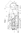
- the vehicle seat E of the present invention is so constructed that the front and rear parts of a seat cushion SC can be moved up and down by rotating two seat lift handles 10A and 10B respectively in the clockwise or counterclockwise directions.
- the feature of the vehicle seat according to the present invention is to unify the two seat lift handles 10A and 10B and a seat lifting device 20 so as to be mounted between two seat base plates 40A and 40B.
- the seat lifting device 20 transmits a force to move the seat cushion up and down in linkage with the rotative motion of the seat lift handle 10A or 10B.
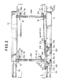
- a pair of lower rails 50 as the seat slide device are arranged on a vehicle floor (not shown) extending in the vehicle front and rear direction (the arrow directions F and R) with a predetermined interval. Further, a pair of upper rails 51 are slidably engaged with the outside surfaces of the lower rails 50, respectively. A pair of seat base plates 40A and 40B are fixed to the upper rails 51, respectively. A seat cushion frame 60 (see Figs. 4 and 5) for fixing the seat cushion SC is supported between these two seat base plates 40A and 40B via the seat lifting device 20. A seat back SB tiltable through a predetermined angle in the front and rear direction is supported between the two seat base plates 40A and 40B via a reclining device (not shown).
- Two pinion gears 25A and 25B and two sector gears 26A and 26B of the seat lifting device 20 are housed between a pair of mounting frames 22A and 22B, and two axles 24A and 24B of the two seat lift handles 10A and 10B are rotatably supported by the mounting frames 22A and 22B.
- the mounting frames 22A and 22B are fixed to the inside surface of the base plate 40A with two caulked pins 21.
- two spring braking mechanisms 27A and 27B are fixed on the outside surface of the mounting frame 22B coaxially with the seat lift handles 10A and 10B, respectively.
- the spring braking mechanism 27A or 27B is a flat spiral spring, for instance whose outer end is connected to the mounting frame 22B and whose inner end is free in contact with the outer circumferential surface of the axle 24A or 24B of the seat lift handle 10A or 10B.
- the seat lift handle 10A or 10B is rotated clockwise, for instance to move up the seat cushion frame 60, since the inner end of the spiral spring is slid on the axle 24A or 24B in the winding off direction, the seat lift handle 10A or 10B is rotatable.
- the two pinion gears 25A and 25B are fixed to the two axles 24A and 24B, respectively and rotatably supported between the two mounting frames 22A and 22B coaxially with the seat lift handles 10A and 10B.
- the two sector gears 26A and 26B are fixed to two axles 28A and 28B, respectively and also rotatably supported between the two mounting frames 22A and 22B in mesh with the pinion gears 25A and 25B, respectively.
- the outer circumferential edge portion of the mounting frame 22A is bent for protection of the seat cushion SC from damage. In this embodiment, since these various gears are covered by the mounting frames 22, no gear cover is additionally required.
- the lower end portion of the two mounting frames 22A and 22B extends toward the upper rail 51 to such an extent that the extension portion 22a thereof is brought into contact with the side surface of the upper rail 51, in order to increase the rigidity of the mounting frames 22 in the transversal direction.
- a pipe- shaped front shaft 30A is pivotally supported by the axle 28A, and the other end of the front shaft 30A is pivotally supported by a hole 40a formed in the seat base plate 40B, so that the front shaft 30A is pivotally supported between the mounting frame 22A and the seat base plate 40B.
- a front sector gear link member 31 A (shown in Figs. 1 and 2) fixed to the front shaft 30A is linked with the front sector gear 26A via a pin 26b (see Fig. 1).
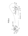
- a first front link lever 31 is fixed to the front shaft 30A.
- a second front link lever 29 is connected to the first front link lever 31 via a pin 31a.
- a pin 26a fixed to an end of the second front link lever 29 is pivotally linked with a hole 61a a formed in a bracket 61 fixed to the front portion of the seat cushion frame 60.
- a third front link lever 32 similar to the first front link lever 31 in the leverage dimension is fixed to the front shaft 30A.
- a fourth front link lever 33 similar to the second front link lever 29 in the leverage dimension is. connected to the third front link lever 32 via a pin 33a.
- a pin 33b fixed to an end of the fourth front link lever 33 is pivotally linked with a hole 62a formed in a bracket 62 fixed to the front portion of the seat cushion frame 60.
- one end of a rear shaft 30B is pivotally supported by a hole formed in a bracket 41 fixed to the seat base plate 40A and the other end of the rear shaft 30B is pivotally supported by a hole 40a formed in the seat base plate 40B, so that the rear shaft 30B is pivotally supported between the two seat base plates 40A and 40B.
- a front end of a rear sector gear link 34 is connected to the rear sector gear 26B via a pin 26c.
- a first rear link lever 35 is fixed to the rear shaft 30B.
- a rear end of the rear sector gear link 34 is connected to the first rear link lever 35 via a pin 35a.
- a pin 35b fixed to an end of the first rear link lever 35 is pivotally linked with a hole 63a a formed in a bracket 63 fixed to the rear portion of the seat cushion frame 60.
- a second rear link lever 36 similar to the first rear link lever 35 in levererage dimension is fixed to the rear shaft 30B.
- a pin 36a fixed to an end of the second rear link lever 36 is pivotally linked with a hole 64a formed in a bracket 64 fixed to the rear portion of the seat cushion frame 60.
- the rear seat lift handle 10B is rotated clockwise in Figs. 1 and 3, since the rear sector gear 26B is rotated counterclockwise via the rear pinion gear 25B, the rear sector gear link 34 is moved jeftward in Fig. 3. Therefore, the rear shaft 30B is rotated counterclockwise via the first rear shaft link lever 35 to move up the seat cushion frame 60 in cooperation with the second rear shaft link lever 36, so that the rear part of the seat cushion SC is adjustably moved in the upward direction.
- the driver's weight applied to the seat cushion frame 60 can be received by the rear spring braking mechanism 27B.
- the rear shaft 30B is rotated clockwise via the first rear shaft link lever 35 to move down the seat cushion frame 60 in cooperation with the second rear shaft link lever 36, so that the rear part of the seat cushion SC is adjustably moved in the downward direction.
- the two lift handles 10A and 10B and the gear sections of the seat cushion lifting device 20 are unified and housed within the two mounting frames 22A and 22B and additionally the mounting frame 22 is fixed to the seat base plate 40A, it is possible to simply assemble vehicle seats E of two different specifications or types by mounting or removing the mounting frames 22 on or from the seat base plate 40A and two shafts 30A and 30B between the two seat base plates 40A and 40B.
- the common seat base plate 40A can be used for vehicle seats of different models, it is possible to reduce the quality management cost.
- the lift handles and the seat cushion lifting device are assembled into a unit, it is possible to assemble vehicle seats of different types by simply mounting or removing the unified assembly on or from the seat base plate, thus reducing the manufacturing and stock cost thereof.
Landscapes
- Engineering & Computer Science (AREA)
- Aviation & Aerospace Engineering (AREA)
- Transportation (AREA)
- Mechanical Engineering (AREA)
- Seats For Vehicles (AREA)
Applications Claiming Priority (2)
| Application Number | Priority Date | Filing Date | Title |
|---|---|---|---|
| JP115177/89U | 1989-09-30 | ||
| JP1989115177U JPH0735783Y2 (ja) | 1989-09-30 | 1989-09-30 | 車両用シート |
Publications (2)
| Publication Number | Publication Date |
|---|---|
| EP0421301A2 true EP0421301A2 (fr) | 1991-04-10 |
| EP0421301A3 EP0421301A3 (en) | 1992-05-06 |
Family
ID=14656256
Family Applications (1)
| Application Number | Title | Priority Date | Filing Date |
|---|---|---|---|
| EP19900118698 Withdrawn EP0421301A3 (en) | 1989-09-30 | 1990-09-28 | Vehicle seat |
Country Status (4)
| Country | Link |
|---|---|
| US (1) | US5150870A (fr) |
| EP (1) | EP0421301A3 (fr) |
| JP (1) | JPH0735783Y2 (fr) |
| KR (1) | KR930011402B1 (fr) |
Cited By (1)
| Publication number | Priority date | Publication date | Assignee | Title |
|---|---|---|---|---|
| GB2303059A (en) * | 1995-07-06 | 1997-02-12 | Fuji Kiko Kk | Seat lifter for motor vehicles |
Families Citing this family (2)
| Publication number | Priority date | Publication date | Assignee | Title |
|---|---|---|---|---|
| DE102016112106B4 (de) | 2016-07-01 | 2019-07-04 | Grammer Ag | Federungsvorrichtung |
| DE102016112105A1 (de) * | 2016-07-01 | 2018-01-04 | Grammer Ag | Federungsvorrichtung |
Family Cites Families (11)
| Publication number | Priority date | Publication date | Assignee | Title |
|---|---|---|---|---|
| JPS58160833U (ja) * | 1982-04-22 | 1983-10-26 | 株式会社今仙電機製作所 | 自動車シ−トハイトアジヤスタ−装置 |
| JPS5958636U (ja) * | 1982-10-12 | 1984-04-17 | トヨタ自動車株式会社 | 座席の上下位置調整装置 |
| JPS60121136A (ja) * | 1983-11-30 | 1985-06-28 | Nissan Motor Co Ltd | 自動車用シ−ト |
| AU576251B2 (en) * | 1984-08-31 | 1988-08-18 | Tachikawa Spring Co. Ltd. | A rotation adjusting apparatus |
| FR2578498B1 (fr) * | 1985-03-07 | 1989-07-13 | Cousin Cie Ets A & M Freres | Dispositif permettant le reglage de l'assiette d'un siege de vehicule |
| JPS6277032U (fr) * | 1985-11-05 | 1987-05-16 | ||
| KR960004301B1 (ko) * | 1986-03-03 | 1996-03-30 | 후지 기꼬오 가부시끼가이샤 | 차량용 시이트 |
| AU584471B2 (en) * | 1986-11-04 | 1989-05-25 | Tachi-S Co., Ltd. | Height adjuster operation mechanism for an automotive seat |
| JPH0534440Y2 (fr) * | 1988-02-29 | 1993-08-31 | ||
| JPH0618836Y2 (ja) * | 1988-09-29 | 1994-05-18 | 池田物産株式会社 | 車両用のシート |
| AU626902B2 (en) * | 1989-08-03 | 1992-08-13 | Tachi-S Co., Ltd. | Height adjusting device for automotive seat |
-
1989
- 1989-09-30 JP JP1989115177U patent/JPH0735783Y2/ja not_active Expired - Lifetime
-
1990
- 1990-09-27 US US07/588,802 patent/US5150870A/en not_active Expired - Fee Related
- 1990-09-28 EP EP19900118698 patent/EP0421301A3/en not_active Withdrawn
- 1990-10-05 KR KR1019900015791A patent/KR930011402B1/ko not_active Expired - Fee Related
Cited By (3)
| Publication number | Priority date | Publication date | Assignee | Title |
|---|---|---|---|---|
| GB2303059A (en) * | 1995-07-06 | 1997-02-12 | Fuji Kiko Kk | Seat lifter for motor vehicles |
| GB2303059B (en) * | 1995-07-06 | 1997-08-27 | Fuji Kiko Kk | Seat lifter for motor vehicles |
| US5775661A (en) * | 1995-07-06 | 1998-07-07 | Fuji Kiko Co., Ltd. | Seat lifter for motor vehicles |
Also Published As
| Publication number | Publication date |
|---|---|
| KR930011402B1 (ko) | 1993-12-06 |
| EP0421301A3 (en) | 1992-05-06 |
| JPH0735783Y2 (ja) | 1995-08-16 |
| KR910006080A (ko) | 1991-04-27 |
| US5150870A (en) | 1992-09-29 |
| JPH0353332U (fr) | 1991-05-23 |
Similar Documents
| Publication | Publication Date | Title |
|---|---|---|
| US4648575A (en) | Height adjusting device for vehicle seat | |
| EP0061394A1 (fr) | Support femoral réglable pour siège de véhicule | |
| EP0410815A1 (fr) | Pédale réglable | |
| US4926987A (en) | One-way transmission device | |
| US5199679A (en) | Height adjusting device for a seat | |
| US4616876A (en) | Rotation adjusting apparatus | |
| US4948081A (en) | Height adjusting device for automotive seat | |
| US4934755A (en) | Back rest with adjustable shoulder rest for the seats of motor vehicles | |
| JP2000127813A (ja) | 自動車座席のための手動高さ調整装置 | |
| US5150870A (en) | Vehicle seat | |
| US4822099A (en) | Rotary seat | |
| US4986509A (en) | Seat lifter | |
| US4871137A (en) | Seat lifting apparatus | |
| US3912215A (en) | Seat construction | |
| EP1132253A2 (fr) | Appareil à levier | |
| JPH0121012B2 (fr) | ||
| JPH0425387Y2 (fr) | ||
| JP4028757B2 (ja) | 車両用シートのリフター構造 | |
| JPH0542910Y2 (fr) | ||
| JPS6313938Y2 (fr) | ||
| JPH1035332A (ja) | 自動車用シートのリフター装置 | |
| JP2533727Y2 (ja) | シートリフター装置の連結パイプ支承構造 | |
| JPH0136687Y2 (fr) | ||
| JPH09301025A (ja) | クッションシートの上下動装置 | |
| JPH026238A (ja) | シートアジャスタ |
Legal Events
| Date | Code | Title | Description |
|---|---|---|---|
| PUAI | Public reference made under article 153(3) epc to a published international application that has entered the european phase |
Free format text: ORIGINAL CODE: 0009012 |
|
| 17P | Request for examination filed |
Effective date: 19900928 |
|
| AK | Designated contracting states |
Kind code of ref document: A2 Designated state(s): DE ES GB |
|
| PUAL | Search report despatched |
Free format text: ORIGINAL CODE: 0009013 |
|
| AK | Designated contracting states |
Kind code of ref document: A3 Designated state(s): DE ES GB |
|
| 17Q | First examination report despatched |
Effective date: 19930224 |
|
| STAA | Information on the status of an ep patent application or granted ep patent |
Free format text: STATUS: THE APPLICATION IS DEEMED TO BE WITHDRAWN |
|
| 18D | Application deemed to be withdrawn |
Effective date: 19930907 |
|
| ITF | It: translation for a ep patent filed |