EP0421324A2 - Structure de panneau indicateur, particulièrement pour véhicules lourds - Google Patents
Structure de panneau indicateur, particulièrement pour véhicules lourds Download PDFInfo
- Publication number
- EP0421324A2 EP0421324A2 EP90118811A EP90118811A EP0421324A2 EP 0421324 A2 EP0421324 A2 EP 0421324A2 EP 90118811 A EP90118811 A EP 90118811A EP 90118811 A EP90118811 A EP 90118811A EP 0421324 A2 EP0421324 A2 EP 0421324A2
- Authority
- EP
- European Patent Office
- Prior art keywords
- plate
- regions
- elements
- panel structure
- region
- Prior art date
- Legal status (The legal status is an assumption and is not a legal conclusion. Google has not performed a legal analysis and makes no representation as to the accuracy of the status listed.)
- Withdrawn
Links
Images

Classifications
-
- F—MECHANICAL ENGINEERING; LIGHTING; HEATING; WEAPONS; BLASTING
- F21—LIGHTING
- F21S—NON-PORTABLE LIGHTING DEVICES; SYSTEMS THEREOF; VEHICLE LIGHTING DEVICES SPECIALLY ADAPTED FOR VEHICLE EXTERIORS
- F21S43/00—Signalling devices specially adapted for vehicle exteriors, e.g. brake lamps, direction indicator lights or reversing lights
- F21S43/20—Signalling devices specially adapted for vehicle exteriors, e.g. brake lamps, direction indicator lights or reversing lights characterised by refractors, transparent cover plates, light guides or filters
- F21S43/26—Refractors, transparent cover plates, light guides or filters not provided in groups F21S43/235 - F21S43/255
-
- B—PERFORMING OPERATIONS; TRANSPORTING
- B60—VEHICLES IN GENERAL
- B60Q—ARRANGEMENT OF SIGNALLING OR LIGHTING DEVICES, THE MOUNTING OR SUPPORTING THEREOF OR CIRCUITS THEREFOR, FOR VEHICLES IN GENERAL
- B60Q1/00—Arrangement of optical signalling or lighting devices, the mounting or supporting thereof or circuits therefor
- B60Q1/26—Arrangement of optical signalling or lighting devices, the mounting or supporting thereof or circuits therefor the devices being primarily intended to indicate the vehicle, or parts thereof, or to give signals, to other traffic
- B60Q1/30—Arrangement of optical signalling or lighting devices, the mounting or supporting thereof or circuits therefor the devices being primarily intended to indicate the vehicle, or parts thereof, or to give signals, to other traffic for indicating rear of vehicle, e.g. by means of reflecting surfaces
- B60Q1/301—Arrangement of optical signalling or lighting devices, the mounting or supporting thereof or circuits therefor the devices being primarily intended to indicate the vehicle, or parts thereof, or to give signals, to other traffic for indicating rear of vehicle, e.g. by means of reflecting surfaces by means of surfaces, e.g. metal plate, reflecting the light of an external light source
Definitions
- the present invention relates to an indicator panel structure particularly for heavy motor vehicles.
- Said panels are commonly constituted by a supporting element to which a plate-like element is applied; the catadioptric elements and the fluorescent elements are accomodated on said plate like element and are arranged inclined, alternating a catadioptric portion to a fluorescent one.
- the catadioptric portions and the fluorescent portions are currently applied on a planar support which is in turn inserted or in any case connected to the supporting element which is then applied directly to the motor vehicle.
- the aim of the present invention is to eliminate the above described disadvantages by providing an indicator panel structure, particularly for heavy motor vehicles, which allows to obtain a rapid and precise assembly of the catadioptric and fluorescent elements.
- a particular object of the invention is to provide an indicator panel structure which can adequately withstand weathering.
- Another object of the present invention is to provide an indicator panel structure which facilitates the combination of alternated inclined elements with the precision required by currently applicable laws.
- Not least object of the present invention is to provide an indicator panel structure particularly for heavy motor vehicles which is relatively easy to manufacture while having modest production costs.
- an indicator panel structure in particular for heavy motor vehicles, which comprises a supporting element which can be applied to said heavy motor vehicle, characterized in that said supporting element has, on its front side, at least one recess for the accommodation of at least one catadioptric plate-like element and, proximate to said at least one recess, at least one raised portion for the application of a fluorescent element.
- the indicator panel structure substantially comprises a supporting element 1 which has, on its front side, recesses 2 alternated with raised portions 3.
- the recesses 2 are intended to accommodate catadioptric polygonal plate-like elements 4.
- These plate-like elements 4 are advantageously in the shape of a right-angled isosceles triangle so as to be able to adapt to the different shapes of the refracting bands required by the laws.
- the plate-like elements 4 are associated within the recesses 2 by means of adhesives, of a snap-together coupling, of welding or of other known coupling means.
- the raised portions 3 are instead intended to receive the fluorescent elements, which can be constituted by panels made of self-adhesive fluorescent material, or can possibly be covered by means of the application of a coat of fluorescent paint, obtaining thereby the same function.
- the depth of the recesses 2 and the height of the plate-like elements 4 is such as to obtain a substantially planar front surface once the plates 4 have been inserted and the fluorescent panels 5, or possibly the coat of fluorescent paint, have been applied.
- the supporting element 1 which can be made of molded synthetic material, has, on its rear side, stiffening ridges defined at the recesses 2 by means of channels 6 and at the raised portions 3 by ribs indicated by 7.
- a raised edge 8 is defined along the outer perimeter of the supporting element 1 and delimits and defines the surfaces useful for gluing or in any case for the application of the panels 5 and for the insertion of the plate-like elements 4.
- figure 1 illustrates bands which are inclined by 45° with respect to the longitudinal extension of the supporting element 1, by using two plates 4 in the shape of a right-angled isosceles triangle coupled at one of their catheti.
- Holes 18 are furthermore defined on the shorter sides of the supporting element 1 for fixing the latter to the heavy motor vehicle by means of known coupling means such as screws, rivets and the like not illustrated in the drawing.
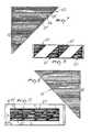
- catadioptric plate-like elements In order to increase the characteristics of reflection and refractivity of the catadioptric plate-like elements it is also possible to use catadioptric plate-like elements with a particular configuration which are illustrated in figures 7 to 10.
- These plate-like elements generally indicated by reference numerals 20 and 21, have a triangular configuration and are characterized by an arrangement of various prism-like elements at predetermined regions.
- Each of the plate-like elements 20 and 21 furthermore has at one cathetus, a reference element 22 which is constituted for example by the inscription TOP, which has the function of identifying the direction of application of the plate-like element so as to make the plate-like elements uniform according to the particular use.
- the peculiarity of the plate-like elements 20 and 21 is determined by a particular arrangement of regions which allow to obtain truly high refractivity values.
- a first region indicated by the reference numeral 25 is provided and has, in the specific example, a band-like extension; this first region 25 is constituted by prisms which create a reflection of light along a direction which is substantially perpendicular to the plane of arrangement of the plate-like element.
- This first region 25 has a preferable but non-limiting width of 9.6 mm.
- the plate-like element 20 furthermore has a second region 26 which is defined by means of prisms having a rectangular base which create a reflection of light with an inclination in one direction comprised between 20° and 30°, preferably 22° and have a preferable width of 8.5 mm.
- At least one third region, indicated by 27, is furthermore provided and is obtained by means of prisms having a rectangular base which create a reflection of light with an angle comprised between 20° and 30°, preferably 22° in a direction which is opposite to the angle of reflection of the second region 26.
- the above mentioned regions preferably have a band-like extension which is parallel to one of the catheti and are arranged so that each first region 25 is flanked by a second region 26 and by a third region 27; each second region 26 and each third region 27 is interposed between two first regions 25.
- the indicator panel structure according to the invention, fully achieves the intended aim, since the particular execution of the supporting element with recesses alternated to raised portions allows the rapid placement and assembly of the catadioptric plate-like elements and of the fluorescent elements.
- the supporting element 1 is configured with a perimetric raised portion 9 which has a width specified by the currently applicable laws and delimits a central recess 10 in which a plurality of plate-like elements 4 can be accomodated.
- a portion of fluorescent material 11 is applied on the perimetric raised portion 9 for example by gluing.
- the particular right angled isosceles triangle shape of the plate-like elements 4 allows, in this case, to obtain a rectangular horizontal band by arranging hypotenuses adjacent to hypotenuses and catheti adjacent to catheti.
- the materials employed, as well as the contingent shapes and dimensions may be any according to the requirements.
Landscapes
- Engineering & Computer Science (AREA)
- General Engineering & Computer Science (AREA)
- Mechanical Engineering (AREA)
- Illuminated Signs And Luminous Advertising (AREA)
Applications Claiming Priority (2)
| Application Number | Priority Date | Filing Date | Title |
|---|---|---|---|
| IT1989A21927A IT8921927A1 (it) | 1989-10-05 | 1989-10-05 | Struttura di placca di segnalazione, particolarmente per automezzi pesanti. |
| IT2192789 | 1989-10-05 |
Publications (2)
| Publication Number | Publication Date |
|---|---|
| EP0421324A2 true EP0421324A2 (fr) | 1991-04-10 |
| EP0421324A3 EP0421324A3 (en) | 1991-07-24 |
Family
ID=11188917
Family Applications (1)
| Application Number | Title | Priority Date | Filing Date |
|---|---|---|---|
| EP19900118811 Withdrawn EP0421324A3 (en) | 1989-10-05 | 1990-10-01 | Indicator panel structure, particularly for heavy motor vehicles |
Country Status (2)
| Country | Link |
|---|---|
| EP (1) | EP0421324A3 (fr) |
| IT (1) | IT8921927A1 (fr) |
Cited By (2)
| Publication number | Priority date | Publication date | Assignee | Title |
|---|---|---|---|---|
| FR2811663A1 (fr) | 2000-07-13 | 2002-01-18 | Commenplus | Materiau luminescent de ragreage et procede de mise en place d'un tel materiau |
| EP1741598A1 (fr) * | 2005-07-08 | 2007-01-10 | Vignal Systems | Feu arrière pour véhicule automobile, en particulier pour une remorque de poids lourd |
Family Cites Families (2)
| Publication number | Priority date | Publication date | Assignee | Title |
|---|---|---|---|---|
| IT7830806V0 (it) * | 1978-09-20 | 1978-09-20 | Starlux Srl | Dispositivo segnaletico particolarmente per automezzi pesanti. |
| IT8522157V0 (it) * | 1985-06-12 | 1985-06-12 | Sacex Spa | Struttura di placca riflettente per autoveicoli pesanti in genere. |
-
1989
- 1989-10-05 IT IT1989A21927A patent/IT8921927A1/it unknown
-
1990
- 1990-10-01 EP EP19900118811 patent/EP0421324A3/en not_active Withdrawn
Cited By (2)
| Publication number | Priority date | Publication date | Assignee | Title |
|---|---|---|---|---|
| FR2811663A1 (fr) | 2000-07-13 | 2002-01-18 | Commenplus | Materiau luminescent de ragreage et procede de mise en place d'un tel materiau |
| EP1741598A1 (fr) * | 2005-07-08 | 2007-01-10 | Vignal Systems | Feu arrière pour véhicule automobile, en particulier pour une remorque de poids lourd |
Also Published As
| Publication number | Publication date |
|---|---|
| EP0421324A3 (en) | 1991-07-24 |
| IT8921927A0 (it) | 1989-10-05 |
| IT8921927A1 (it) | 1991-04-05 |
Similar Documents
| Publication | Publication Date | Title |
|---|---|---|
| DE3674952D1 (de) | Wulstverstaerkung fuer lkw-reifen. | |
| ATE59817T1 (de) | Warndreieck fuer kraftfahrzeuge. | |
| DE3776155D1 (de) | Von einem motor angetriebene servolenkung fuer ein fahrzeug. | |
| AU6368686A (en) | Wobble plate type compressor with variable displacement compressor | |
| GB2109039A (en) | Reflective road studs and a method of forming such studs | |
| DE69003341D1 (de) | Schrägscheibenverdichter mit einem Mechanismus zur Veränderung der Verdrängung. | |
| EP0421324A2 (fr) | Structure de panneau indicateur, particulièrement pour véhicules lourds | |
| US6409368B1 (en) | Lighting device for vehicles | |
| ATA114086A (de) | Antriebsanordnung fuer kraftfahrzeuge mit wenigstens zwei triebachsen | |
| EP0017356B1 (fr) | Diffuseur pour feu de signalisation de véhicule automobile | |
| US5402266A (en) | Vehicle reflector unit | |
| ATA290889A (de) | Servolenkung fuer ein fahrzeug, insbesondere ein motorboot | |
| EP0886101B1 (fr) | Lampe pour véhicules automobiles | |
| EP1029738A3 (fr) | Lampe de véhicule pour l'éclairage de la plaque d'immatriculation ou l'indication de direction | |
| KR200145124Y1 (ko) | 도로안내용 반사표지판 | |
| US7434965B2 (en) | Reflector for a linear light source and louvre controller incorporating the same | |
| DE59809772D1 (de) | Instrumententafel mit Leuchtquellen in einem Kraftfahrzeug | |
| EP0208152A2 (fr) | Structure de plaque réfléchissante pour poids lourd | |
| KR200158708Y1 (ko) | 천정판의 조립식 원형 등받이판 | |
| SU1135561A2 (ru) | Режущий инструмент | |
| DE3761637D1 (de) | Signaleinheit fuer kraftfahrzeuge mit zwei abgestumpften leuchtenden flaechen. | |
| GB1596062A (en) | Reflector for fixing to the spokes of bicycle wheels | |
| DE69517272D1 (de) | Kraftfahrzeugscheinwerfer mit einem eine komplexe Oberfläche aufweisenden Reflektor | |
| KR0129784Y1 (ko) | 조명용 프리즘 | |
| DE58903292D1 (de) | Reflektor fuer einen fahrzeugscheinwerfer. |
Legal Events
| Date | Code | Title | Description |
|---|---|---|---|
| PUAI | Public reference made under article 153(3) epc to a published international application that has entered the european phase |
Free format text: ORIGINAL CODE: 0009012 |
|
| AK | Designated contracting states |
Kind code of ref document: A2 Designated state(s): AT BE CH DE DK ES FR GB GR IT LI LU NL SE |
|
| PUAL | Search report despatched |
Free format text: ORIGINAL CODE: 0009013 |
|
| AK | Designated contracting states |
Kind code of ref document: A3 Designated state(s): AT BE CH DE DK ES FR GB GR IT LI LU NL SE |
|
| STAA | Information on the status of an ep patent application or granted ep patent |
Free format text: STATUS: THE APPLICATION IS DEEMED TO BE WITHDRAWN |
|
| 18D | Application deemed to be withdrawn |
Effective date: 19920125 |