EP0421505B1 - Dispositif de régulation d'une pression hydraulique, adapté en particulier à des moules pour matière céramique avec matrice inférieure mobile et contre-matrice - Google Patents
Dispositif de régulation d'une pression hydraulique, adapté en particulier à des moules pour matière céramique avec matrice inférieure mobile et contre-matrice Download PDFInfo
- Publication number
- EP0421505B1 EP0421505B1 EP90202381A EP90202381A EP0421505B1 EP 0421505 B1 EP0421505 B1 EP 0421505B1 EP 90202381 A EP90202381 A EP 90202381A EP 90202381 A EP90202381 A EP 90202381A EP 0421505 B1 EP0421505 B1 EP 0421505B1
- Authority
- EP
- European Patent Office
- Prior art keywords
- die
- hydraulic
- chamber
- valve
- counter
- Prior art date
- Legal status (The legal status is an assumption and is not a legal conclusion. Google has not performed a legal analysis and makes no representation as to the accuracy of the status listed.)
- Expired - Lifetime
Links
- 239000000919 ceramic Substances 0.000 title claims abstract description 17
- 239000004927 clay Substances 0.000 claims abstract description 19
- 239000012530 fluid Substances 0.000 claims abstract description 17
- 238000003825 pressing Methods 0.000 claims abstract description 10
- 230000001105 regulatory effect Effects 0.000 claims 1
- 239000000843 powder Substances 0.000 description 4
- 239000000463 material Substances 0.000 description 3
- 239000002245 particle Substances 0.000 description 3
- 238000000605 extraction Methods 0.000 description 2
- 238000010276 construction Methods 0.000 description 1
- 230000003111 delayed effect Effects 0.000 description 1
- 230000008021 deposition Effects 0.000 description 1
- 230000008030 elimination Effects 0.000 description 1
- 238000003379 elimination reaction Methods 0.000 description 1
- 239000010419 fine particle Substances 0.000 description 1
- 239000011261 inert gas Substances 0.000 description 1
- 238000004519 manufacturing process Methods 0.000 description 1
- 238000000034 method Methods 0.000 description 1
- 238000011084 recovery Methods 0.000 description 1
- 238000007789 sealing Methods 0.000 description 1
- 239000000725 suspension Substances 0.000 description 1
Images
Classifications
-
- B—PERFORMING OPERATIONS; TRANSPORTING
- B28—WORKING CEMENT, CLAY, OR STONE
- B28B—SHAPING CLAY OR OTHER CERAMIC COMPOSITIONS; SHAPING SLAG; SHAPING MIXTURES CONTAINING CEMENTITIOUS MATERIAL, e.g. PLASTER
- B28B3/00—Producing shaped articles from the material by using presses; Presses specially adapted therefor
- B28B3/02—Producing shaped articles from the material by using presses; Presses specially adapted therefor wherein a ram exerts pressure on the material in a moulding space; Ram heads of special form
-
- B—PERFORMING OPERATIONS; TRANSPORTING
- B30—PRESSES
- B30B—PRESSES IN GENERAL
- B30B15/00—Details of, or accessories for, presses; Auxiliary measures in connection with pressing
- B30B15/16—Control arrangements for fluid-driven presses
Definitions
- This invention relates to a hydraulic press with a hydraulic pressure regulator device for hydraulic circuits of ceramic presses equipped with forming moulds with a mobile bottom die and a counter-die.
- a hydraulic press with a hydraulic pressure regulator device for hydraulic circuits of ceramic presses equipped with forming moulds with a mobile bottom die and a counter-die.
- the bottom die cavities are closed by hydraulically controlled punches which form the laying face of the tiles, whereas the cavities of the counter-die are closed upperly by punches which form the exposed face of the tiles.
- said upper punches are arranged to move independently of the counter-die so as to occupy two opposing positions, namely a withdrawn (or raised) position and an advanced (or lowered) position, in the second of which they extract the tiles from the cavities in the counter-die.
- the upper punches are lowered (according to the aforesaid document) by at least one first hydraulic chamber which is connected to the hydraulic circuit of the press via a valve, whereas said upper punches are raised, after said first chamber has been discharged via said valve, by the clay which is in a compacted state in the cavities of the counter-die.
- Said upper punches are maintained in their raised position by a second hydraulic chamber which is permanently connected to a pressurized hydraulic reservoir, in which the pressure is maintained by an inert gas atmosphere.
- a further problem which arises in such known moulds is that the expulsion of the formed tiles from the counter-die (and their simultaneous deposition on the temporarily raised lower punches) must take place at a level as close as possible to that of the raised lower punches, otherwise an excessive distance of fall can result in tile breakage, in particular with large formats.
- the proposed device is particularly suitable for ceramic moulds of the initially described type, and comprises two intercommunicating chambers of which one is connected to the hydraulic circuit which drives the lower punches relative to the bottom die, and the other is connected to at least one hydraulic chamber which drives the upper punches relative to the counter-die, the first of said two chambers housing an elastically loaded valve arranged to close or not close the connection between the two chambers, and the second of said two chambers housing the active end of a slidable push rod sensitive to the pressure in said first chamber via a conduit which connects said first chamber to the seat of said push rod.
- said means during the raising of the mould counter-die said first chamber is pressurized by the hydraulic fluid from said lower punch operating circuit, and the same fluid, via said conduit, causes the push rod to advance and thus the valve to open, with consequent passage of said fluid into the hydraulic chamber for operating the upper punches.
- the pressurized hydraulic fluid from said chamber for operating the upper punches causes the push rod to withdraw so that it discharges through the passage port existing between said two chambers and established by said valve, after which this latter closes.
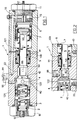
- Figure 1 is an axial section through the invention, with parts cut away to better illustrate parts which would otherwise be hidden.
- Figure 2 shows part of the section on the line II-II of Figure 1, to a reduced scale.
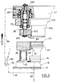
- Figure 3 is a partial sectional view of a ceramic mould equipped with the invention and arranged on a hydraulic press.
- the device comprises an elongate outer shell or casing 100 through which a longitudinal hole with different cross-sections passes and is closed by two end plugs 10 and 11 respectively.
- said longitudinal hole houses a pin 2 for adjusting the loading of a facing helical thrust spring 3; a cup-shaped passage valve 4 mounted on said spring 3; a push rod 5 for opening said valve 4; a piston 6 for controlling said push rod 5; and a counteracting spring 7 which is mounted slackly on the rod 5 and rests at its ends against said casing 100 and against said piston 6.
- the distance between the facing ends of the piston 6 and the plug 11 and thus the loading of the spring 7 can be adjusted by a screw 12 screwed into said plug 11.
- the operating position of the pin 2 and thus the loading of the spring 3 can be adjusted by the adjustment screw 13 screwed into the plug 10.
- annular chamber 122 into which two conduits 33 (Figure 2) and 121 ( Figure 1) open, the valve 4 being provided with a channel 40 for connecting said chamber 122 to the rear housing of the spring 3.
- the conduit 33 (see Figure 3) is connected to a conduit 66 the purpose of which is specified hereinafter, while the conduit 121 terminates at the plug 11 ( Figure 1).
- a flow regulator valve 44 and a non-return valve 55 are connected in parallel as can be seen in Figure 1. That end of the valve 4 which faces the rod 5 has a conical sealing surface 42 with which there corresponds on the casing 100 a valve seat 41 through which the active end of the rod 5 can pass, as described hereinafter.
- the reference numeral 43 indicates a passage hole for the removal/recovery of possible seepages.
- the plug 11 comprises a right-angled conduit 16, of which the radial part opens into an annular chamber 15 between said plug 11 and said casing 100, the longitudinal part allowing free passage of said screw 12 and opening in front of said piston 6.
- annular chamber 15 is connected to said conduit 121 (see Figure 1), the reference numeral 99 indicating an interchangeable travel-limiting disc lying between the piston 6 and the spring 7.
- this shows part of a usual ceramic press of the type comprising a vertically mobile bottom die and a counter-die, and which will be described in terms only of its essential parts, reference to the initially mentioned document being suggested for further details.
- FIG. 3 shows a pressing plate 17 intended to be placed on the bed (not shown) of a usual hydraulic ceramic press, a platform 18 fixed to said plate 17, a plate 19 provided above the platform 18 and driven vertically by cylinder-piston units (not shown) connected via the conduit 66 to the hydraulic circuit of said press, and a series of punches 20 for forming the laying face of the tiles and which are fixed to said plate 19.
- the punches 20 are slidingly received in corresponding cavities 21 for loading the soft clay 23, these latter being formed in a bottom die 24.
- the bottom die 24 is mounted to slide relative to the platform 18 on underlying cylindrical bars 25, on these latter there being mounted respective compressed springs 26 arranged to keep the bottom die 24 completely raised.
- the vertical travel of the bottom die 24 can be achieved by convenient hydraulic cylinder-piston units.
- a counter-die 240 comprising cavities 210 in which respective punches 200 are slidingly mounted for forming the exposed face of the tiles.
- the punches 200 are fixed to an overlying plate 190 which is secured to the mobile cross-member 27 of the press.
- each piston 29 and said mobile cross-member 27 there are provided an upper hydraulic chamber 280 connected to the conduit 88 and a lower chamber 281 for collecting any seepage.
- the device of the invention operates as follows. At the beginning of the cycle the mould is in the configuration shown in Figure 3 with the plate 190 separated from the cross-member, and the device of the invention is in the configuration shown in Figure 1 with the conduit 88 under pressure and the conduit 33 connected to discharge.
- the cross-member 27 is lowered to rest against the bottom die 24, which in its turn is lowered.
- the situation is such that the punches 20 approach the punches 200, with simultaneous transfer of the clay 523 from the cavities 21 to the cavities 210, it being pressed both from below and from above.
- the opening of the valve 4 can be adjusted as required using the adjustment screw 13, by which a choice can be made of the resistance offered by the upper punch 200 to the thrust of the clay 23 as it is transferred, and thus the duration of the total rearward stroke of said upper punch 200, ie until the plate 190 rests against the cross-member 27. Because of this delay or braking or timing of the rearward travel of the upper punch 200 compared with its virtually free travel in the known art, the deaeration period of the clay 23 can be considerably increased, with the result that statistically all the finer particles contained in the clay 23 leave the cavity 210.
- the exposed surface of the tile is virtually free of very fine powdery material, so that the subsequent application and adhesion of the glaze presents no problems, or alternatively the exposed surface of tiles which are not to undergo glazing, such as those in porcelainized fine ceramic sandstone, have a virtually complete "velvet" appearance which is characteristic of such unglazed materials.
- valve 4 On termination of the pressing stage the valve 4 ( Figure 1, 2) is closed and the counter-die 240 is raised followed by the bottom die 24, together with the tiles contained in the cavities 210.
- the punches 20 are also simultaneously raised under the control of said cylinder-piston units, which are fed with pressurized hydraulic fluid through the conduit 66 (see Figure 3).
- the same hydraulic fluid passes through the conduit 33 to reach the chamber 122, to then enter the conduit 121 and pass through the valve 44 to reach the conduit 16 (see Figure 1).
- This causes the piston 6 to advance against the thrust of the spring 7, said piston 6 causing the rod 5 to advance after a small free movement defined by the gap between the disc 99 and the rod 5.
Landscapes
- Engineering & Computer Science (AREA)
- Mechanical Engineering (AREA)
- Manufacturing & Machinery (AREA)
- Chemical & Material Sciences (AREA)
- Ceramic Engineering (AREA)
- Press-Shaping Or Shaping Using Conveyers (AREA)
- Press Drives And Press Lines (AREA)
Claims (6)
- Presse hydraulique avec dispositif de réglage de la pression hydraulique, spéciale pour les matrices pour céramique à monter sur cette presse.
Cette presse est formée par une matrice inférieure se déplaçant dans le sens vertical (24) et possédant au moins une cavité (21) pour l'introduction de l'argile molle (23) et par une contre-matrice supérieure se déplacant dans le sens vertical (240) et formée d'au moins une cavité (210) en correspondance de la précédente (21); ces cavités (21, 210) sont closes dans leur partie supérieure par les emporte-pièce (20,200) qui forment, respectivement, la face de pose et la face visible du carreau: ces emporte-pièce (20,200) sont reliés au circuit hydraulique de la presse de façon à être actionnés indépendamment des matrices (24) et des contre-matrices (240) correspondantes; le dispositif est caractérisé par deux chambres intercommuniquantes (122, 22) par l'intermédiaire d'une soupape (4): la première chambre (122) est reliée au circuit hydraulique (66) pour l'actionnement des emporte-pièces inférieurs (20) de la matrice inférieure (24) alors que la deuxième chambre est reliée à au moins une chambre hydraulique (280) pour l'actionnement des emporte-pièce supérieurs (200) de la contre-matrice (240). La soupape (4) est élastiquement poussée dans la direction d'une tige de commande qui se déplace en avant (5,6) et dont le siège est relié à la première chambre citée ci-dessus (122) de façon à ce que, lorsque cette dernière est mise sous pression par le fluide hydraulique provenant du circuit (66), la tige de commande (5,6) provoque l'ouverture de la soupape (4) et l'entrée simultanée du fluide dans la chambre hydraulique (280). Lorsque les emporte-pièce supérieurs (200) se déplacent en arrière pendant la phase de pressage, la soupape (4) se ferme après avoir évacué le fluide de la chambre hydraulique (280). - Presse hydraulique avec dispositif semblable à celui indiqué dans la revendication 1, caractérisée par la tige de commande (5,6) qui comprend:- une tige coulissante (5) montée étanchément dans le corps (100) du dispositif (1), du même côté que la deuxième chambre (22).- un piston coulissant situé à l'arrière (6), monté dans le corps et légèrement éloignée de la tige ci-dessus (5) lorsque le tuyau (121) qui relie la première chambre (122) au siège du piston (6) est relié à l'évacuation.- un ressort de compression (7) placé entre le corps (100) et le piston (6), et- une butée avant (50) qui sert de fin de course de recul et est placée à l'extrémité avant de cette tige (5).
- Presse hydraulique avec dispositif semblable aux revendiactions précédentes, caracterisée par une soupape servant au réglage du flux (44) du fluide allant vers le piston (6) et par une soupape de non retour (55) pour le passage du fluide allant vers la première chambre (122). Elles sont reliées en parallèle dans le circuit (121).
- Presse hydraulique avec dispositif semblable à la revendication 1, caracterisée par l'association de la soupape (4) avec des dispositifs placés à l'arrière (13) pour le réglage du ressort de poussée (3) correspondant.
- Presse hydraulique avec dispositif conforme aux revendications 1 et 2, caracterisée par l'association avec le piston (6) de dispositifs (12) pour le réglage de la tension du ressort de compression (7) et d'un disque de support (99) placé entre le ressort (7) et le piston. Le disque est interchangeable de facon à sélectionner la course nécessaire au piston (6) en fonction de la tige (5)
- Matrice pour céramique avec partie inférieure mobile et contre-matrice, caractérisée par la présence d'au moins un dispositif (1) conforme aux revendications de 1 à 5, servant a retarder le recul des emporte-pièce supérieurs (200) pendant les phases de pressage et à régler l'avancement des matrices supérieures pendant le relevage de la contre-matrice (240).
Priority Applications (1)
| Application Number | Priority Date | Filing Date | Title |
|---|---|---|---|
| AT90202381T ATE97360T1 (de) | 1989-10-02 | 1990-09-07 | Vorrichtung zum regeln eines hydraulischen druckes, insbesondere fuer keramikformpressen mit beweglichem unterstempel und gegenstempel. |
Applications Claiming Priority (2)
| Application Number | Priority Date | Filing Date | Title |
|---|---|---|---|
| IT4687189 | 1989-10-02 | ||
| IT04687189A IT1237568B (it) | 1989-10-02 | 1989-10-02 | Dispositivo idraulico regolatore di pressione,tipicamente per stampi ceramici con matrice mobile e contromatrice |
Publications (3)
| Publication Number | Publication Date |
|---|---|
| EP0421505A2 EP0421505A2 (fr) | 1991-04-10 |
| EP0421505A3 EP0421505A3 (en) | 1991-11-27 |
| EP0421505B1 true EP0421505B1 (fr) | 1993-11-18 |
Family
ID=11260010
Family Applications (1)
| Application Number | Title | Priority Date | Filing Date |
|---|---|---|---|
| EP90202381A Expired - Lifetime EP0421505B1 (fr) | 1989-10-02 | 1990-09-07 | Dispositif de régulation d'une pression hydraulique, adapté en particulier à des moules pour matière céramique avec matrice inférieure mobile et contre-matrice |
Country Status (4)
| Country | Link |
|---|---|
| EP (1) | EP0421505B1 (fr) |
| AT (1) | ATE97360T1 (fr) |
| DE (1) | DE69004658T2 (fr) |
| IT (1) | IT1237568B (fr) |
Families Citing this family (2)
| Publication number | Priority date | Publication date | Assignee | Title |
|---|---|---|---|---|
| DE10357423A1 (de) * | 2003-12-04 | 2005-06-30 | Rolls-Royce Deutschland Ltd & Co Kg | Schnellschlussventil zum Unterbrechen eines Fluidstroms |
| ITAN20110141A1 (it) | 2011-10-19 | 2013-04-20 | Manenti S P A | Tampone migliorato per stampo per l'industria ceramica e stampo comprendente un tale tampone. |
Family Cites Families (5)
| Publication number | Priority date | Publication date | Assignee | Title |
|---|---|---|---|---|
| US1682172A (en) * | 1928-08-28 | Automatic hydraulic press | ||
| FR641383A (fr) * | 1927-09-24 | 1928-08-02 | Dispositif de commande de mécanismes à pression, à actions sucessives | |
| IT1107475B (it) * | 1978-07-24 | 1985-11-25 | Merisinter Spa | Complesso di pressa e porta-stampo per la compattazione nella metallurgia delle polveri |
| IT1187779B (it) * | 1985-04-10 | 1987-12-23 | Mass Spa | Stampo ceramico con matrice mobile per la formatura di piastrelle di qualsiasi formato e di piastrelle con supproto a piu' componenti,come le piastrelle presso-smaltate |
| DE3527594A1 (de) * | 1985-08-01 | 1987-02-12 | Sacmi | Presse, insbesondere fuer die herstellung von keramikfliesen |
-
1989
- 1989-10-02 IT IT04687189A patent/IT1237568B/it active IP Right Grant
-
1990
- 1990-09-07 EP EP90202381A patent/EP0421505B1/fr not_active Expired - Lifetime
- 1990-09-07 AT AT90202381T patent/ATE97360T1/de not_active IP Right Cessation
- 1990-09-07 DE DE90202381T patent/DE69004658T2/de not_active Expired - Fee Related
Also Published As
| Publication number | Publication date |
|---|---|
| IT8946871A1 (it) | 1991-04-02 |
| DE69004658T2 (de) | 1994-03-10 |
| DE69004658D1 (de) | 1993-12-23 |
| EP0421505A2 (fr) | 1991-04-10 |
| IT8946871A0 (it) | 1989-10-02 |
| ATE97360T1 (de) | 1993-12-15 |
| EP0421505A3 (en) | 1991-11-27 |
| IT1237568B (it) | 1993-06-08 |
Similar Documents
| Publication | Publication Date | Title |
|---|---|---|
| CA1056574A (fr) | Methode et dispositif de compactage de poudres | |
| US3868201A (en) | Powdered metal press | |
| CA1056573A (fr) | Dispositif et methode de compactage de materiaux en particules | |
| US4915159A (en) | Method and apparatus for compacting foundry mold making material about a foundry mold pattern | |
| US3647332A (en) | Hydraulic press | |
| EP1671723B1 (fr) | Matrice segmentée et procédé de fabrication d'une pièce compactée à partir de poudre métallique | |
| CA1161793A (fr) | Dispositif et methode de faconnage d'un article creux par application d'une pression interne | |
| US4342212A (en) | Indirect extrusion press | |
| EP0421505A2 (fr) | Dispositif de régulation d'une pression hydraulique, adapté en particulier à des moules pour matière céramique avec matrice inférieure mobile et contre-matrice | |
| US4563144A (en) | Hydraulic block press | |
| US5040967A (en) | Means for vertically moving a ram in a compression molding machine | |
| EP1716998B1 (fr) | Appareil et procédé pour contrôler le compactage par un dispositif de compression isostatique | |
| SU1150054A1 (ru) | Устройство дл жидкой или полужидкой штамповки | |
| EP0569069B1 (fr) | Moule pour la fabrication de carreaux en céramique et moyens d'alimentation de ce moule | |
| KR100308371B1 (ko) | 곡물 착유기 | |
| JPS629049Y2 (fr) | ||
| CN115946209B (zh) | 一种用于耐火材料的免烧制备方法 | |
| SU929326A1 (ru) | Прессформа дл прессовани порошковых изделий с полостью | |
| SU682323A1 (ru) | Пресс-форма дл прессовани порошка | |
| EP0566171B1 (fr) | Dispositif d'asservissement d'un moule pour matière céramique | |
| SU1194577A1 (ru) | Пресс-форма дл штамповки изделий из пористых заготовок | |
| SU1228969A1 (ru) | Устройство дл прессовани из порошка изделий сложной формы | |
| JPH0829364B2 (ja) | プレス機械のダイクッション装置 | |
| JPH0710829Y2 (ja) | 生型造型設備における圧縮空気吹込み装置 | |
| JPH04258398A (ja) | 粉末加圧成形体の成形・取出し方法と装置 |
Legal Events
| Date | Code | Title | Description |
|---|---|---|---|
| PUAI | Public reference made under article 153(3) epc to a published international application that has entered the european phase |
Free format text: ORIGINAL CODE: 0009012 |
|
| AK | Designated contracting states |
Kind code of ref document: A2 Designated state(s): AT BE CH DE DK ES FR GB GR IT LI LU NL SE |
|
| PUAL | Search report despatched |
Free format text: ORIGINAL CODE: 0009013 |
|
| AK | Designated contracting states |
Kind code of ref document: A3 Designated state(s): AT BE CH DE DK ES FR GB GR IT LI LU NL SE |
|
| 17P | Request for examination filed |
Effective date: 19920131 |
|
| 17Q | First examination report despatched |
Effective date: 19920817 |
|
| GRAA | (expected) grant |
Free format text: ORIGINAL CODE: 0009210 |
|
| AK | Designated contracting states |
Kind code of ref document: B1 Designated state(s): AT BE CH DE DK ES FR GB GR IT LI LU NL SE |
|
| PG25 | Lapsed in a contracting state [announced via postgrant information from national office to epo] |
Ref country code: SE Effective date: 19931118 Ref country code: NL Effective date: 19931118 Ref country code: LI Effective date: 19931118 Ref country code: GR Free format text: LAPSE BECAUSE OF FAILURE TO SUBMIT A TRANSLATION OF THE DESCRIPTION OR TO PAY THE FEE WITHIN THE PRESCRIBED TIME-LIMIT Effective date: 19931118 Ref country code: FR Free format text: THE PATENT HAS BEEN ANNULLED BY A DECISION OF A NATIONAL AUTHORITY Effective date: 19931118 Ref country code: ES Free format text: THE PATENT HAS BEEN ANNULLED BY A DECISION OF A NATIONAL AUTHORITY Effective date: 19931118 Ref country code: DK Effective date: 19931118 Ref country code: CH Effective date: 19931118 Ref country code: BE Effective date: 19931118 Ref country code: AT Effective date: 19931118 |
|
| REF | Corresponds to: |
Ref document number: 97360 Country of ref document: AT Date of ref document: 19931215 Kind code of ref document: T |
|
| REF | Corresponds to: |
Ref document number: 69004658 Country of ref document: DE Date of ref document: 19931223 |
|
| ITF | It: translation for a ep patent filed | ||
| REG | Reference to a national code |
Ref country code: CH Ref legal event code: PL |
|
| NLV1 | Nl: lapsed or annulled due to failure to fulfill the requirements of art. 29p and 29m of the patents act | ||
| PGFP | Annual fee paid to national office [announced via postgrant information from national office to epo] |
Ref country code: GB Payment date: 19940902 Year of fee payment: 5 |
|
| PLBE | No opposition filed within time limit |
Free format text: ORIGINAL CODE: 0009261 |
|
| STAA | Information on the status of an ep patent application or granted ep patent |
Free format text: STATUS: NO OPPOSITION FILED WITHIN TIME LIMIT |
|
| PG25 | Lapsed in a contracting state [announced via postgrant information from national office to epo] |
Ref country code: LU Free format text: LAPSE BECAUSE OF NON-PAYMENT OF DUE FEES Effective date: 19940930 |
|
| PGFP | Annual fee paid to national office [announced via postgrant information from national office to epo] |
Ref country code: DE Payment date: 19941020 Year of fee payment: 5 |
|
| 26N | No opposition filed | ||
| PG25 | Lapsed in a contracting state [announced via postgrant information from national office to epo] |
Ref country code: GB Effective date: 19950907 |
|
| GBPC | Gb: european patent ceased through non-payment of renewal fee |
Effective date: 19950907 |
|
| PG25 | Lapsed in a contracting state [announced via postgrant information from national office to epo] |
Ref country code: DE Effective date: 19960601 |
|
| PG25 | Lapsed in a contracting state [announced via postgrant information from national office to epo] |
Ref country code: IT Free format text: LAPSE BECAUSE OF NON-PAYMENT OF DUE FEES;WARNING: LAPSES OF ITALIAN PATENTS WITH EFFECTIVE DATE BEFORE 2007 MAY HAVE OCCURRED AT ANY TIME BEFORE 2007. THE CORRECT EFFECTIVE DATE MAY BE DIFFERENT FROM THE ONE RECORDED. Effective date: 20050907 |