EP0421550A1 - Procédé d'ajustement d'un système de commande pour un dispositif de chauffage avec un brûleur et un système de commande pour un tel dispositif - Google Patents
Procédé d'ajustement d'un système de commande pour un dispositif de chauffage avec un brûleur et un système de commande pour un tel dispositif Download PDFInfo
- Publication number
- EP0421550A1 EP0421550A1 EP90202648A EP90202648A EP0421550A1 EP 0421550 A1 EP0421550 A1 EP 0421550A1 EP 90202648 A EP90202648 A EP 90202648A EP 90202648 A EP90202648 A EP 90202648A EP 0421550 A1 EP0421550 A1 EP 0421550A1
- Authority
- EP
- European Patent Office
- Prior art keywords
- control system
- heating installation
- memory
- group
- stored
- Prior art date
- Legal status (The legal status is an assumption and is not a legal conclusion. Google has not performed a legal analysis and makes no representation as to the accuracy of the status listed.)
- Granted
Links
Images


Classifications
-
- F—MECHANICAL ENGINEERING; LIGHTING; HEATING; WEAPONS; BLASTING
- F23—COMBUSTION APPARATUS; COMBUSTION PROCESSES
- F23N—REGULATING OR CONTROLLING COMBUSTION
- F23N5/00—Systems for controlling combustion
-
- F—MECHANICAL ENGINEERING; LIGHTING; HEATING; WEAPONS; BLASTING
- F23—COMBUSTION APPARATUS; COMBUSTION PROCESSES
- F23N—REGULATING OR CONTROLLING COMBUSTION
- F23N5/00—Systems for controlling combustion
- F23N5/26—Details
- F23N5/265—Details using electronic means
-
- F—MECHANICAL ENGINEERING; LIGHTING; HEATING; WEAPONS; BLASTING
- F23—COMBUSTION APPARATUS; COMBUSTION PROCESSES
- F23N—REGULATING OR CONTROLLING COMBUSTION
- F23N5/00—Systems for controlling combustion
- F23N5/20—Systems for controlling combustion with a time program acting through electrical means, e.g. using time-delay relays
- F23N5/203—Systems for controlling combustion with a time program acting through electrical means, e.g. using time-delay relays using electronic means
-
- G—PHYSICS
- G05—CONTROLLING; REGULATING
- G05B—CONTROL OR REGULATING SYSTEMS IN GENERAL; FUNCTIONAL ELEMENTS OF SUCH SYSTEMS; MONITORING OR TESTING ARRANGEMENTS FOR SUCH SYSTEMS OR ELEMENTS
- G05B19/00—Program-control systems
- G05B19/02—Program-control systems electric
- G05B19/04—Program control other than numerical control, i.e. in sequence controllers or logic controllers
- G05B19/042—Program control other than numerical control, i.e. in sequence controllers or logic controllers using digital processors
-
- F—MECHANICAL ENGINEERING; LIGHTING; HEATING; WEAPONS; BLASTING
- F23—COMBUSTION APPARATUS; COMBUSTION PROCESSES
- F23N—REGULATING OR CONTROLLING COMBUSTION
- F23N2223/00—Signal processing; Details thereof
- F23N2223/04—Memory
-
- F—MECHANICAL ENGINEERING; LIGHTING; HEATING; WEAPONS; BLASTING
- F23—COMBUSTION APPARATUS; COMBUSTION PROCESSES
- F23N—REGULATING OR CONTROLLING COMBUSTION
- F23N2223/00—Signal processing; Details thereof
- F23N2223/08—Microprocessor; Microcomputer
-
- F—MECHANICAL ENGINEERING; LIGHTING; HEATING; WEAPONS; BLASTING
- F23—COMBUSTION APPARATUS; COMBUSTION PROCESSES
- F23N—REGULATING OR CONTROLLING COMBUSTION
- F23N2223/00—Signal processing; Details thereof
- F23N2223/38—Remote control
-
- F—MECHANICAL ENGINEERING; LIGHTING; HEATING; WEAPONS; BLASTING
- F23—COMBUSTION APPARATUS; COMBUSTION PROCESSES
- F23N—REGULATING OR CONTROLLING COMBUSTION
- F23N2227/00—Ignition or checking
- F23N2227/20—Calibrating devices
Definitions
- the invention relates to a method for the production of a control system for a heating installation with a burner, comprising the production of a central processing unit with a microcomputer and a memory for storing therein a control program to be processed by the microcomputer and containing instructions for receiving measurment signals originating from sensors and instructions for controlling actuators of the heating installation depending on the values of the measurement signals, the instructions containing parameters.
- a method of this type is known in practice. With the known method, for each type of heating installation and for each application environment thereof a corresponding control system is designed and produced.
- the number of types of heating installations and associated control systems in large, inter alia because different safety requirements have to be complied with in different countries.
- the cost for the design and production of a control system for application of the known method are therefore high.
- the cost price is increased because a relatively large number of different control systems have to be kept in stock.
- Another drawback is that the control system can be adapted to changed circumstances, such as the use of different measurement sensors or actuators or different safety requirements, only with difficulty and at relatively high cost.
- the aim of the invention is to overcome the drawbacks of the known method.
- this objective is achieved according to the invention in that, after the production of the physical control system and the storing of the program in the memory, a group of values of variable parameters dependent on the use of the control system is stored from outside the control system in a rewritable section of the memory.
- the control system can, after the physical production thereof, be programmed simply for use in a specific type of heating installation and for specific conditions of use.
- the group of variable parameter values can be entered into the memory of the control system at any time after the physical production of said unit, for example during manufacture of a heating installation and installation of the control system therein, when there is a change in circumstances at the premises of the user of the heating installation and when replacing the control system if it is defective.
- the input can be effected by means of a stationary programming unit during production of the heating installation or by means of a portable programming unit for programming the heating installation on the user's premises.
- a stationary programming unit during production of the heating installation
- a portable programming unit for programming the heating installation on the user's premises.
- the number of types of control systems which have to be physically manufactured and kept in stock is limited to one. Consequently, the cost price of the control system is minimized.
- the control system can be reprogrammed for the changed circumstances simply and inexpensively on the premises of the user of the heating installation, as a result of which fresh insights into desired control characteristics or safety features of the heating installation can be accepted more easily by the use and implemented inexpensively.
- the method is such that a variable parameter is assigned to each group of variable parameters, said parameter having a value assigned exclusively to the group, and that, after installation of the control system in a heating installation and after entering the variable parameter values into the memory, the program detects the type of this heating installation and compares a value corresponding to the detected type with a stored value of the parameter assigned exclusively to the group of variable parameters and gives an error signal if parity is not found.
- the program detects the type of this heating installation and compares a value corresponding to the detected type with a stored value of the parameter assigned exclusively to the group of variable parameters and gives an error signal if parity is not found.
- the method is preferably further such that, after parity has been found during the comparison, the functioning of the heating installation is tested in accordance with the stored program and the stored parameters, that the control system transmits measurement data obtained while carrying out the test, that a computer receives the measurement data via a receiver unit and compares said data with corresponding data stored in the computer and that the computer gives an error signal if parity is not found.
- an extra check is obtained on the correctness of the group of variable parameter values entered in the memory, for example if a fault arises when detecting the type of heating installation in which the control system has been installed.
- This method also has the advantage that the heating installation can be checked, in particular immediately after production thereof, to ensure that it is functioning correctly, it being possible for any defects in the heating installation to be signalled in a simple manner at an early stage.
- the group of variable parameter values is transmitted, without the use of wires, from a programming unit to the control system and then stored in the memory.
- a relatively trouble-free transmission of the group of variable parameter values to the control system is obtained by this means.
- This is a particular advantageous if programming has to be carried out relatively very frequently by means of the programming unit, for example during the series production of heating installations and the installation of control systems therein.
- This advantage is also obtained if the measurement data obtained during a test on the heating installation are transmitted, without the use of wires, by the control system to a receiver unit of another computer.
- the other computer can be a stationary main computer which is used for programming control systems in heating installations produced in series or can be a portable computer unit which can be connected at a latter time for processing the measurement data using yet another computer.
- the invention also relates to a control system for use of the method according to the invention according to one or more of Claims 6 to 13.
- a heating installation with a burner, to be controlled is indicated by reference numeral 1.
- the heating installation is controlled by a control system comprising a control unit 2, a remote operating unit 3 and a remote programming unit 4 which is to be used during the production or maintenance of the control unit and which preferably can be connected via a modem 5 to a computer 6.
- the control unit 2 has a central processing circuit 7, which can be formed by a monolithic microcomputer with a memory, of which one section (EEROM), which is preferably non-volatile, is electrically erasable and rewritable for storing therein parameter values associated with a desired functional performance of the operation of a heating installation, in which the control unit 2 has to be installed, and dependent on the use of the heating installation 1, said parameter values being those of instructions for the microcomputer which correspond to the desired performance.
- EEROM one section
- a microcomputer of this type can be a 68HC05B6 from Motorola.
- the processing circuit 7 is connected to a coupling circuit 8, which can be an application specific integrated circuit (ASIC) with analog and digital circuits.
- the coupling circuit 8 has a number of inputs and outputs 9 for receiving measurement signals, for example from temperature and pressure sensors, and for supplying actuating signals to, for example, a fan, values and spark ignition elements.
- Some of the connections 9 are connected to the remote operating unit 3 for the, if appropriate time-dependent, setting of the desired temperature in a specific room and for setting a specific heating pattern if appropriate.
- Some functions of the remote operating unit 3 could also be fulfilled by an operating unit 10, of the control unit 2, connected to the processing circuit 8.
- the operating units 3 and 10 can comprise display screens for displaying the settings made and measured values.
- An input 11 of the coupling circuit 8 is connected to the junction of the voltage divider, connected to a voltage source with a voltage V, of a resistor 12 installed in the control unit 2 and a resistor 13 installed in the heating installation 1. Irrespective of the type of heating installation 1 for which the control unit 2 is used, the resistor 12 has a fixed value and the resistor 13 has a specific value assigned to the heating installation 1. As a result, the voltage at the input 11 corresponds to the type and the application environment (for example depending on national requirements) of the heating installation 1.
- An output 14 of the coupling circuit 8 is connected to an output unit 15.
- An input 16 of the coupling circuit 8 is connected to an input unit 17.
- the units 15 and 17 are preferably an infrared transmitter and an infrared receiver respectively, for communication with a infrared receiver 18 and an infrared transmitter 19, which are connected to a processing circuit 20 of the remove programming unit 4.
- the use of the stand-alone programming unit 4 and the lack of switches and/or electrical connecting elements between the control unit 2 and the programming unit 4 prevents it being possible for unauthorized persons deliberately or accidentally to modify the programmed data. Because there is no electrical connection, the communication can be established in an electrically safe and rapid manner.
- the programming unit 4 can be of more or less complex nature depending on the application, production of maintenance of heating installations 1.
- the programming unit 4 has a connection for connection to the modem 5 for communication with a computer 6 for data exchange, for example by down-loading data to the programming unit 4 and for storing and processing measurement data from a heating installation 1 under test.
- the first step, block 21, after BEGIN in the flow chart comprises the production of the physical control system, in particular of the control unit 2.
- a program is stored in the memory of the central processing circuit 7 of the control unit 2, which program, with the exception of variable parameter values which are still to be input, is suitable for use for the control and protection of various types of heating installations 1 and application environments thereof.
- the control system in particular the control unit 2 is fitted in the heating installation 1.
- the heating installation 1 has the resistor 13 with a specific value dependent on the type of heating installation 1 and on the application environment of the heating installation 1.
- step 23 a group of variable parameter values is input by means of the programming unit 4 into the memory of the processing circuit 7. By this means the said program is completed.
- the group of variable parameter values comprises a characteristic value X assigned to the group.
- step 24 a value Y which is determined by the voltage deivider 12, 13 and corresponds to the type and the application of the heating installation 1, in which the control unit 2 is fitted, is detected.
- step 25 the characteristic value X received in the memory of the processing unit 7 is compared with the detected value Y. If X is identical to Y, the end of the production function shown in Fig. 2 is reached. If it follows from the comparison that X is not equal to Y, the control system gives an error signal, in block 26, and it is then possible to return to block 23 for re-inputting a group of variable parameter values, possibly with a different characteristic value X, into the memory.
- step 21 the flow diagram shown in Fig. 2 can also be used for maintenance of the control system if the heating installation, in which it is fitted, has already been installed and has operated in accordance with the said program.
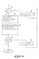
- Fig. 3 shows a section of the flow chart which, compared with Fig. 2, is modified as an extension of the method according to the invention. If the characteristic value X stored in the memory of the processing circuit 7 is identical to the corresponding value Y a step, block 28, follows in accordance with Fig. 3, in which step the heating installation is allowed to operate in accordance with the stored completed program and the control system transmits measurement data V obtained from the heating installation to a monitoring computer.
- predetermined data W corresponding to the measurement data V are read from a background memory in the monitoring computer.
- the monitoring computer then compares the measurement data V and the corresponding predetermined data W with one another.
- circuits 7 and 8 can be formed on a single substrate or part circuits thereof can be formed on different substrates.
- the detection of the type of heating installation 1 can also take place in another manner, for example by replacing the register 13 by a zener diode and measuring the voltage at the input 11 relative to the voltage V, or by using a multi-wire connection between the control unit 2 and the installation 1, the various wires of which, depending on the type of heating installation, are connected therein with points with different voltages.
Landscapes
- Engineering & Computer Science (AREA)
- Chemical & Material Sciences (AREA)
- Combustion & Propulsion (AREA)
- Mechanical Engineering (AREA)
- General Engineering & Computer Science (AREA)
- General Physics & Mathematics (AREA)
- Physics & Mathematics (AREA)
- Automation & Control Theory (AREA)
- Regulation And Control Of Combustion (AREA)
- Control Of Temperature (AREA)
- Control Of Combustion (AREA)
- Control By Computers (AREA)
- Feeding And Controlling Fuel (AREA)
- Selective Calling Equipment (AREA)
Applications Claiming Priority (2)
| Application Number | Priority Date | Filing Date | Title |
|---|---|---|---|
| NL8902492 | 1989-10-06 | ||
| NL8902492A NL8902492A (nl) | 1989-10-06 | 1989-10-06 | Werkwijze voor het vervaardigen van een besturingsstelsel voor een verwarmingsinrichting met een brander, en een besturingsstelsel voor een dergelijke inrichting. |
Publications (2)
| Publication Number | Publication Date |
|---|---|
| EP0421550A1 true EP0421550A1 (fr) | 1991-04-10 |
| EP0421550B1 EP0421550B1 (fr) | 1994-07-20 |
Family
ID=19855416
Family Applications (1)
| Application Number | Title | Priority Date | Filing Date |
|---|---|---|---|
| EP90202648A Expired - Lifetime EP0421550B1 (fr) | 1989-10-06 | 1990-10-04 | Procédé d'ajustement d'un système de commande pour un dispositif de chauffage avec un brûleur et un système de commande pour un tel dispositif |
Country Status (6)
| Country | Link |
|---|---|
| EP (1) | EP0421550B1 (fr) |
| JP (1) | JPH03148518A (fr) |
| KR (1) | KR910008525A (fr) |
| AT (1) | ATE108884T1 (fr) |
| DE (1) | DE69010818T2 (fr) |
| NL (1) | NL8902492A (fr) |
Cited By (9)
| Publication number | Priority date | Publication date | Assignee | Title |
|---|---|---|---|---|
| EP0566177A1 (fr) * | 1992-03-27 | 1993-10-20 | Encon B.V. | Dispositif de commande automatique de brûleur pour un appareil à gaz, noamment pour une chaudière de chauffage central |
| EP0468803A3 (fr) * | 1990-07-27 | 1994-05-04 | Raymond Corp | |
| EP0654719A1 (fr) * | 1993-11-19 | 1995-05-24 | Landis & Gyr Technology Innovation AG | Dispositif de commande et de régulation configurable |
| WO1998057239A1 (fr) * | 1997-06-10 | 1998-12-17 | Honeywell Inc. | Commande repartie utilisant des concepts de groupe |
| FR2782782A1 (fr) * | 1998-09-02 | 2000-03-03 | Cuenod Thermotech Sa | Bruleur a systeme d'affichage |
| EP0821777A4 (fr) * | 1995-04-19 | 2000-04-12 | Bowin Tech Pty Ltd | Appareil de chauffage |
| EP1028361A1 (fr) * | 1999-02-03 | 2000-08-16 | IABER S.p.A. | Commande à distance pour chaudière |
| EP0931990A3 (fr) * | 1998-01-23 | 2001-12-12 | Tridelta Industries, Inc. | Commande d'appareil |
| EP1258680A3 (fr) * | 2001-05-16 | 2004-12-29 | Monox Limited | Module de sécurité pour un brûleur et un appareil utilisant un tel module |
Citations (6)
| Publication number | Priority date | Publication date | Assignee | Title |
|---|---|---|---|---|
| FR2544096A1 (fr) * | 1983-04-07 | 1984-10-12 | El Si Sa Entreprise | Dispositif pour la synchronisation sequentielle d'appareils et/ou machines electriques ou electroniques |
| EP0124330A1 (fr) * | 1983-04-21 | 1984-11-07 | Autoflame Engineering Limited | Systèmes de commande pour brûleurs à carburant |
| GB2188452A (en) * | 1986-03-29 | 1987-09-30 | Teves Gmbh Alfred | Programmed electronic controller |
| DE3723024A1 (de) * | 1987-07-11 | 1989-01-19 | Bosch Gmbh Robert | Verfahren und vorrichtung zur steuerung von technischen anlagen und maschinen |
| EP0332607A2 (fr) * | 1988-03-10 | 1989-09-13 | VOEST-ALPINE AUTOMOTIVE Gesellschaft m.b.H. | Commande électronique pour véhicule à moteur avec moteur à combustion |
| EP0155403B1 (fr) * | 1984-03-20 | 1993-03-03 | Robert Bosch Gmbh | Dispositif de commande pour véhicules à moteur |
-
1989
- 1989-10-06 NL NL8902492A patent/NL8902492A/nl not_active Application Discontinuation
-
1990
- 1990-09-25 KR KR1019900015226A patent/KR910008525A/ko not_active Abandoned
- 1990-10-04 DE DE69010818T patent/DE69010818T2/de not_active Expired - Lifetime
- 1990-10-04 EP EP90202648A patent/EP0421550B1/fr not_active Expired - Lifetime
- 1990-10-04 AT AT90202648T patent/ATE108884T1/de not_active IP Right Cessation
- 1990-10-05 JP JP2269307A patent/JPH03148518A/ja active Pending
Patent Citations (6)
| Publication number | Priority date | Publication date | Assignee | Title |
|---|---|---|---|---|
| FR2544096A1 (fr) * | 1983-04-07 | 1984-10-12 | El Si Sa Entreprise | Dispositif pour la synchronisation sequentielle d'appareils et/ou machines electriques ou electroniques |
| EP0124330A1 (fr) * | 1983-04-21 | 1984-11-07 | Autoflame Engineering Limited | Systèmes de commande pour brûleurs à carburant |
| EP0155403B1 (fr) * | 1984-03-20 | 1993-03-03 | Robert Bosch Gmbh | Dispositif de commande pour véhicules à moteur |
| GB2188452A (en) * | 1986-03-29 | 1987-09-30 | Teves Gmbh Alfred | Programmed electronic controller |
| DE3723024A1 (de) * | 1987-07-11 | 1989-01-19 | Bosch Gmbh Robert | Verfahren und vorrichtung zur steuerung von technischen anlagen und maschinen |
| EP0332607A2 (fr) * | 1988-03-10 | 1989-09-13 | VOEST-ALPINE AUTOMOTIVE Gesellschaft m.b.H. | Commande électronique pour véhicule à moteur avec moteur à combustion |
Non-Patent Citations (1)
| Title |
|---|
| PATENT ABSTRACTS OF JAPAN vol. 12, no. 197 (M-706)(3044) 8 June 1988, & JP-A-63 3126 (TOSHIBA) 8 January 1988, * |
Cited By (10)
| Publication number | Priority date | Publication date | Assignee | Title |
|---|---|---|---|---|
| EP0468803A3 (fr) * | 1990-07-27 | 1994-05-04 | Raymond Corp | |
| EP0566177A1 (fr) * | 1992-03-27 | 1993-10-20 | Encon B.V. | Dispositif de commande automatique de brûleur pour un appareil à gaz, noamment pour une chaudière de chauffage central |
| EP0654719A1 (fr) * | 1993-11-19 | 1995-05-24 | Landis & Gyr Technology Innovation AG | Dispositif de commande et de régulation configurable |
| EP0821777A4 (fr) * | 1995-04-19 | 2000-04-12 | Bowin Tech Pty Ltd | Appareil de chauffage |
| WO1998057239A1 (fr) * | 1997-06-10 | 1998-12-17 | Honeywell Inc. | Commande repartie utilisant des concepts de groupe |
| EP0931990A3 (fr) * | 1998-01-23 | 2001-12-12 | Tridelta Industries, Inc. | Commande d'appareil |
| FR2782782A1 (fr) * | 1998-09-02 | 2000-03-03 | Cuenod Thermotech Sa | Bruleur a systeme d'affichage |
| EP0984224A1 (fr) * | 1998-09-02 | 2000-03-08 | Compagnie Europeenne de Bruleurs | Brûleur à système d'affichage |
| EP1028361A1 (fr) * | 1999-02-03 | 2000-08-16 | IABER S.p.A. | Commande à distance pour chaudière |
| EP1258680A3 (fr) * | 2001-05-16 | 2004-12-29 | Monox Limited | Module de sécurité pour un brûleur et un appareil utilisant un tel module |
Also Published As
| Publication number | Publication date |
|---|---|
| DE69010818D1 (de) | 1994-08-25 |
| NL8902492A (nl) | 1991-05-01 |
| JPH03148518A (ja) | 1991-06-25 |
| DE69010818T2 (de) | 1994-10-27 |
| ATE108884T1 (de) | 1994-08-15 |
| KR910008525A (ko) | 1991-05-31 |
| EP0421550B1 (fr) | 1994-07-20 |
Similar Documents
| Publication | Publication Date | Title |
|---|---|---|
| US5549469A (en) | Multiple burner control system | |
| US4090248A (en) | Supervisory and control system for environmental conditioning equipment | |
| US4923117A (en) | Microcomputer-controlled system with redundant checking of sensor outputs | |
| US7069201B1 (en) | Apparatus for use in an industrial process and plant including such apparatuses as well as method for simulating operation of such a plant | |
| US4403297A (en) | Process control system prover | |
| EP0421550A1 (fr) | Procédé d'ajustement d'un système de commande pour un dispositif de chauffage avec un brûleur et un système de commande pour un tel dispositif | |
| US20030004682A1 (en) | Furnace diagnostic system | |
| EP0755037A1 (fr) | Détecteur de fumée photoélectrique et système de prévention de sinistres utilisant celui-ci | |
| US5608657A (en) | Interactive diagnostic system | |
| US5350237A (en) | Temperature measuring circuit for heating and cooking appliances | |
| EP1717653B1 (fr) | Dispositif de sécurité | |
| US6629022B1 (en) | Motor vehicle control unit | |
| US6199422B1 (en) | Method and system for fast probe failure determination | |
| CZ288586B6 (cs) | Diagnostický systém pro topný přístroj zabudovaný ve vozidle | |
| JP2001159913A (ja) | 限界スイッチの機能検査方法 | |
| US5432805A (en) | Method of detecting transmission error in disaster prevention supervisory system | |
| US6339373B1 (en) | Sensor device providing indication of device health | |
| US6737614B2 (en) | Method of checking a device for influencing the temperature in the cooking space of a baking oven and corresponding baking oven | |
| US6239697B1 (en) | Fire alarm system | |
| US4506255A (en) | Operation test circuit for fire detectors | |
| CN113495824A (zh) | 用于操作系统的方法 | |
| US2988694A (en) | Automatic fault locator | |
| EP0636954A1 (fr) | Tableau de commande pour des chaudières | |
| US4692884A (en) | Remote operation of optical system | |
| US7154425B2 (en) | Supervised input converter |
Legal Events
| Date | Code | Title | Description |
|---|---|---|---|
| PUAI | Public reference made under article 153(3) epc to a published international application that has entered the european phase |
Free format text: ORIGINAL CODE: 0009012 |
|
| 17P | Request for examination filed |
Effective date: 19901127 |
|
| AK | Designated contracting states |
Kind code of ref document: A1 Designated state(s): AT BE CH DE DK ES FR GB IT LI LU NL SE |
|
| 17Q | First examination report despatched |
Effective date: 19930416 |
|
| RAP1 | Party data changed (applicant data changed or rights of an application transferred) |
Owner name: NEFIT FASTO B.V. |
|
| GRAA | (expected) grant |
Free format text: ORIGINAL CODE: 0009210 |
|
| ITF | It: translation for a ep patent filed | ||
| AK | Designated contracting states |
Kind code of ref document: B1 Designated state(s): AT BE CH DE DK ES FR GB IT LI LU NL SE |
|
| PG25 | Lapsed in a contracting state [announced via postgrant information from national office to epo] |
Ref country code: AT Effective date: 19940720 Ref country code: CH Effective date: 19940720 Ref country code: BE Effective date: 19940720 Ref country code: LI Effective date: 19940720 Ref country code: ES Free format text: THE PATENT HAS BEEN ANNULLED BY A DECISION OF A NATIONAL AUTHORITY Effective date: 19940720 Ref country code: DK Effective date: 19940720 |
|
| REF | Corresponds to: |
Ref document number: 108884 Country of ref document: AT Date of ref document: 19940815 Kind code of ref document: T |
|
| REF | Corresponds to: |
Ref document number: 69010818 Country of ref document: DE Date of ref document: 19940825 |
|
| ET | Fr: translation filed | ||
| PG25 | Lapsed in a contracting state [announced via postgrant information from national office to epo] |
Ref country code: SE Effective date: 19941020 |
|
| PG25 | Lapsed in a contracting state [announced via postgrant information from national office to epo] |
Ref country code: LU Free format text: LAPSE BECAUSE OF NON-PAYMENT OF DUE FEES Effective date: 19941031 |
|
| REG | Reference to a national code |
Ref country code: CH Ref legal event code: PL |
|
| PLBI | Opposition filed |
Free format text: ORIGINAL CODE: 0009260 |
|
| 26 | Opposition filed |
Opponent name: JOH. VAILLANT GMBH U. CO. Effective date: 19950419 |
|
| NLR1 | Nl: opposition has been filed with the epo |
Opponent name: JOH. VAILLANT GMBH U. CO. |
|
| PLBO | Opposition rejected |
Free format text: ORIGINAL CODE: EPIDOS REJO |
|
| PLBN | Opposition rejected |
Free format text: ORIGINAL CODE: 0009273 |
|
| STAA | Information on the status of an ep patent application or granted ep patent |
Free format text: STATUS: OPPOSITION REJECTED |
|
| 27O | Opposition rejected |
Effective date: 19961122 |
|
| NLR2 | Nl: decision of opposition | ||
| NLT1 | Nl: modifications of names registered in virtue of documents presented to the patent office pursuant to art. 16 a, paragraph 1 |
Owner name: NEFIT BUDERUS B.V. |
|
| REG | Reference to a national code |
Ref country code: FR Ref legal event code: CD |
|
| REG | Reference to a national code |
Ref country code: GB Ref legal event code: IF02 |
|
| PLAB | Opposition data, opponent's data or that of the opponent's representative modified |
Free format text: ORIGINAL CODE: 0009299OPPO |
|
| PGFP | Annual fee paid to national office [announced via postgrant information from national office to epo] |
Ref country code: GB Payment date: 20090929 Year of fee payment: 20 |
|
| PGFP | Annual fee paid to national office [announced via postgrant information from national office to epo] |
Ref country code: DE Payment date: 20091026 Year of fee payment: 20 |
|
| PGFP | Annual fee paid to national office [announced via postgrant information from national office to epo] |
Ref country code: NL Payment date: 20091030 Year of fee payment: 20 |
|
| PGFP | Annual fee paid to national office [announced via postgrant information from national office to epo] |
Ref country code: IT Payment date: 20091027 Year of fee payment: 20 Ref country code: FR Payment date: 20091113 Year of fee payment: 20 |
|
| REG | Reference to a national code |
Ref country code: NL Ref legal event code: V4 Effective date: 20101004 |
|
| REG | Reference to a national code |
Ref country code: GB Ref legal event code: PE20 Expiry date: 20101003 |
|
| PG25 | Lapsed in a contracting state [announced via postgrant information from national office to epo] |
Ref country code: NL Free format text: LAPSE BECAUSE OF EXPIRATION OF PROTECTION Effective date: 20101004 |
|
| PG25 | Lapsed in a contracting state [announced via postgrant information from national office to epo] |
Ref country code: GB Free format text: LAPSE BECAUSE OF EXPIRATION OF PROTECTION Effective date: 20101003 |
|
| PG25 | Lapsed in a contracting state [announced via postgrant information from national office to epo] |
Ref country code: DE Free format text: LAPSE BECAUSE OF EXPIRATION OF PROTECTION Effective date: 20101004 |