EP0421596B1 - Support pour garniture d'étanchéité à labyrinthe - Google Patents
Support pour garniture d'étanchéité à labyrinthe Download PDFInfo
- Publication number
- EP0421596B1 EP0421596B1 EP90309372A EP90309372A EP0421596B1 EP 0421596 B1 EP0421596 B1 EP 0421596B1 EP 90309372 A EP90309372 A EP 90309372A EP 90309372 A EP90309372 A EP 90309372A EP 0421596 B1 EP0421596 B1 EP 0421596B1
- Authority
- EP
- European Patent Office
- Prior art keywords
- labyrinth seal
- pins
- frettage
- foot
- guide vane
- Prior art date
- Legal status (The legal status is an assumption and is not a legal conclusion. Google has not performed a legal analysis and makes no representation as to the accuracy of the status listed.)
- Expired - Lifetime
Links
- 239000000463 material Substances 0.000 claims description 5
- WAIPAZQMEIHHTJ-UHFFFAOYSA-N [Cr].[Co] Chemical compound [Cr].[Co] WAIPAZQMEIHHTJ-UHFFFAOYSA-N 0.000 description 1
- 238000002485 combustion reaction Methods 0.000 description 1
- 238000011065 in-situ storage Methods 0.000 description 1
- 238000003780 insertion Methods 0.000 description 1
- 230000037431 insertion Effects 0.000 description 1
- 238000003754 machining Methods 0.000 description 1
- 238000012423 maintenance Methods 0.000 description 1
- 239000002184 metal Substances 0.000 description 1
- 238000000034 method Methods 0.000 description 1
- 239000000843 powder Substances 0.000 description 1
- 239000007921 spray Substances 0.000 description 1
- 238000005507 spraying Methods 0.000 description 1
- 238000011144 upstream manufacturing Methods 0.000 description 1
- 239000013585 weight reducing agent Substances 0.000 description 1
Images

Classifications
-
- F—MECHANICAL ENGINEERING; LIGHTING; HEATING; WEAPONS; BLASTING
- F01—MACHINES OR ENGINES IN GENERAL; ENGINE PLANTS IN GENERAL; STEAM ENGINES
- F01D—NON-POSITIVE DISPLACEMENT MACHINES OR ENGINES, e.g. STEAM TURBINES
- F01D11/00—Preventing or minimising internal leakage of working-fluid, e.g. between stages
- F01D11/001—Preventing or minimising internal leakage of working-fluid, e.g. between stages for sealing space between stator blade and rotor
-
- F—MECHANICAL ENGINEERING; LIGHTING; HEATING; WEAPONS; BLASTING
- F01—MACHINES OR ENGINES IN GENERAL; ENGINE PLANTS IN GENERAL; STEAM ENGINES
- F01D—NON-POSITIVE DISPLACEMENT MACHINES OR ENGINES, e.g. STEAM TURBINES
- F01D11/00—Preventing or minimising internal leakage of working-fluid, e.g. between stages
- F01D11/02—Preventing or minimising internal leakage of working-fluid, e.g. between stages by non-contact sealings, e.g. of labyrinth type
- F01D11/025—Seal clearance control; Floating assembly; Adaptation means to differential thermal dilatations
-
- Y—GENERAL TAGGING OF NEW TECHNOLOGICAL DEVELOPMENTS; GENERAL TAGGING OF CROSS-SECTIONAL TECHNOLOGIES SPANNING OVER SEVERAL SECTIONS OF THE IPC; TECHNICAL SUBJECTS COVERED BY FORMER USPC CROSS-REFERENCE ART COLLECTIONS [XRACs] AND DIGESTS
- Y10—TECHNICAL SUBJECTS COVERED BY FORMER USPC
- Y10T—TECHNICAL SUBJECTS COVERED BY FORMER US CLASSIFICATION
- Y10T403/00—Joints and connections
- Y10T403/70—Interfitted members
- Y10T403/7018—Interfitted members including separably interposed key
-
- Y—GENERAL TAGGING OF NEW TECHNOLOGICAL DEVELOPMENTS; GENERAL TAGGING OF CROSS-SECTIONAL TECHNOLOGIES SPANNING OVER SEVERAL SECTIONS OF THE IPC; TECHNICAL SUBJECTS COVERED BY FORMER USPC CROSS-REFERENCE ART COLLECTIONS [XRACs] AND DIGESTS
- Y10—TECHNICAL SUBJECTS COVERED BY FORMER USPC
- Y10T—TECHNICAL SUBJECTS COVERED BY FORMER US CLASSIFICATION
- Y10T403/00—Joints and connections
- Y10T403/70—Interfitted members
- Y10T403/7075—Interfitted members including discrete retainer
- Y10T403/7077—Interfitted members including discrete retainer for telescoping members
- Y10T403/7079—Transverse pin
Definitions
- the present invention relates to support means for labyrinth seals.
- the invention has particular efficacy when utilised in gas turbine engines.
- a known example of a labyrinth seal of the kind mentioned herein is illustrated and described in US patent specification 3411794 and is defined by an outer annular land which has a number of annular fins formed on its outer diameter, the fins being surrounded in close spaced relationship by a further annular land, the bore of which has an abradable lining.
- the finned portion is coaxially fixed to a rotor for rotation therewith within the lined portion which in turn, is non rotatably supported by the inner ends of a fixed stage of stators or guide vanes.
- Radial slots have to be machined in the opposing face of at least one of the flanges and the features placed therein, to be restrained against excessive movement peripherally of the flanges, by the side walls of the slots.
- the arrangement is expensive to produce and heavy.
- the present invention seeks to provide an improved outer labyrinth seal land of the kind defined hereinbefore.
- a labyrinth seal support structure for supporting a labyrinth seal in a turbine of a gas turbine engine, comprising a ring of guide vanes each of which has a radially inwardly projecting foot, fixing pins which pass through a double flange structure on the labyrinth seal and engage with said feet characterised in that two pins made from anti frettage material are provided, one on each side of each guide vane foot each pin having a flat thereon for engagement with an adjacent edge of a respective guide vane foot and including a metallic anti frettage liner comprised of a plurality of arcuate segments of 'U' cross-section which nest between said double flanges and include holes for passage through of said pins and wherein said 'U' section segments have lips which are turned outwardly, inwardly and upwardly so as to provide edges which clip into grooves in faces of said double flange structure.
- a gas turbine engine 10 includes a compressor 12, combustion equipment 14, a turbine section 16 and an exhaust section 18, all arranged in flow series.
- the turbine section has a stage of guide vanes 20 affixed in known manner via their radially outer ends, to structure within the engine turbine casing 22.
- a stage of rotatable turbine blades 24 is positioned immediately downstream of the stage of guide vanes 22, again in known manner.
- the turbine disc 26 has an annular land 28 bolted to its upstream face, which land extends forwardly and terminates under the guide vanes 20. That portion of the land 28 which lies under the guide vanes 20 has annular fins 30 formed on its outer diameter in known manner and these are surrounded in close spaced relationship by a further annular land 32 which has an abradable lining (not shown in Figure 1) in its bore, again in known manner.
- the land 32 with its associated abradable lining 34 has an outwardly turned annular flange 36 formed at its downstream end.
- the flange 36 has an annular groove 38 formed in its periphery, and an anti frettage liner, which for reasons of clarity is shown in Figure 6, nests therein.
- a plurality of equi-angularly spaced pairs of holes 40, only one of which pairs is shown, are drilled through the resulting walls 42 of the groove 38 and a pin 44 is fitted in each hole 42. It is intended that the pins 44 should stay in situ until their replacement through wear is necessitated. They may thus be a press fit or may be brazed via their ends to the groove walls 42, or both.
- Each pin 44 in a pair of pins is spaced one from the other by a distance which will allow the insertion of a foot 46 therebetween one of which feet 46 projects from the underside of each respective guide vane 20. It follows that the number of pairs of pins 44 equals the number of guide vanes 20 in the stage.
- Each guide vane 20 is affixed via its outer end to fixed engine structure in known manner. Consequently, during operation of the engine 10, when the guide vanes 20 become heated, they expand radially inwardly towards the engine axis. Conversely the land 32 and its associated grooved flange 36 expand radially outwardly from the engine axis. Thus there must be an appropriate clearance between the feet 46 and the associated pins 44. This is shown in Figures 2 and 4. There must also be a clearance between the feet 46 and the walls 42 of the groove 38. This is shown in Figure 3.
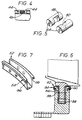
- the pins 44 in the present example are relieved at 48 and 50 respectively, so as to provide flat opposing faces. A greater surface area is thus provided for the feet 46 (not shown in Figure 5) to bear on. This, depending on the friction characteristics of the assembly, which would be ascertained on test of the associated engine, may prove to be an unnecessary step.
- the anti frettage liner 52 as depicted in Figure 6 and which could e.g. be made from a material sold under the proprietry name "HAYNES 25", (registered trade mark), is used to cover the profile of the groove 38.
- the preform 52 which is depicted per se in Figure 7 could be produced by hot spraying as with a plasma gun, a metal powder onto a disposable core (not shown) and would have its lips 54 turned inwardly upon themselves so as to provide upwardly turned edges 56 within the maximum width of the preform 52 and which on fitting of the preform within the groove 38, will clip into further grooves 58 and 60 in the outer surfaces of the walls 42.
- the pins 44 will be manufactured from the anti frettage material.
Landscapes
- Engineering & Computer Science (AREA)
- Mechanical Engineering (AREA)
- General Engineering & Computer Science (AREA)
- Turbine Rotor Nozzle Sealing (AREA)
- Structures Of Non-Positive Displacement Pumps (AREA)
Claims (1)
- Structure de support de garniture d'étanchéité à labyrinthe pour supporter une garniture d'étanchéité à labyrinthe dans une turbine d'un moteur à turbine à gaz, comprenant une couronne d'aubes de guidage (20) qui ont chacune un pied (46) saillant radialement vers l'intérieur, des goujons de fixation (44) qui passent à travers une structure à brides doubles (42) sur la garniture d'étanchéité à labyrinthe et sont en prises avec ledit pied (46), caractérisée en ce que deux goujons (44) réalisés en matériau anti-frottement sont prévus, un sur chaque côté de chaque pied (46) d'aube de guidage, chaque goujon (44) comportant un plat (48) destiné à être mis en prise avec un bord adjacent d'un pied (46) d'aube de guidage respectif et comprenant une garniture métallique anti-frottement (52) comprenant d'une pluralité des segments courbés de section transversale en U qui s'emboîtent entre lesdites brides doubles (42) et comprend des trous pour le passage desdits goujons (44) au travers et dans lequel lesdits segments de section en U ont des lèvres (54) qui sont dirigés vers l'extérieur, l'intérieur et vers le haut pour réaliser des bords (56) qui s'insèrent dans des gorges (58 ou 60) dans les faces de ladite structure à brides doubles.
Applications Claiming Priority (2)
| Application Number | Priority Date | Filing Date | Title |
|---|---|---|---|
| GB8922339 | 1989-10-04 | ||
| GB898922339A GB8922339D0 (en) | 1989-10-04 | 1989-10-04 | Improvements in or relating to labyrinth seal structures |
Publications (3)
| Publication Number | Publication Date |
|---|---|
| EP0421596A2 EP0421596A2 (fr) | 1991-04-10 |
| EP0421596A3 EP0421596A3 (en) | 1991-07-03 |
| EP0421596B1 true EP0421596B1 (fr) | 1994-05-25 |
Family
ID=10664027
Family Applications (1)
| Application Number | Title | Priority Date | Filing Date |
|---|---|---|---|
| EP90309372A Expired - Lifetime EP0421596B1 (fr) | 1989-10-04 | 1990-08-28 | Support pour garniture d'étanchéité à labyrinthe |
Country Status (5)
| Country | Link |
|---|---|
| US (1) | US5073084A (fr) |
| EP (1) | EP0421596B1 (fr) |
| JP (1) | JPH03149324A (fr) |
| DE (1) | DE69009136T2 (fr) |
| GB (1) | GB8922339D0 (fr) |
Cited By (1)
| Publication number | Priority date | Publication date | Assignee | Title |
|---|---|---|---|---|
| WO2024194585A1 (fr) * | 2023-03-23 | 2024-09-26 | Safran Aircraft Engines | Ensemble pour turbomachine |
Families Citing this family (22)
| Publication number | Priority date | Publication date | Assignee | Title |
|---|---|---|---|---|
| US5749218A (en) * | 1993-12-17 | 1998-05-12 | General Electric Co. | Wear reduction kit for gas turbine combustors |
| US5435693A (en) * | 1994-02-18 | 1995-07-25 | Solar Turbines Incorporated | Pin and roller attachment system for ceramic blades |
| US5421703A (en) * | 1994-05-25 | 1995-06-06 | General Electric Company | Positively retained vane bushing for an axial flow compressor |
| JP3327814B2 (ja) * | 1997-06-18 | 2002-09-24 | 三菱重工業株式会社 | ガスタービンのシール装置 |
| JPH11294189A (ja) * | 1998-02-27 | 1999-10-26 | United Technol Corp <Utc> | 回転機械用のステ―タ構造体 |
| FR2776012B1 (fr) * | 1998-03-12 | 2000-04-07 | Snecma | Joint d'etancheite d'un etage d'aubes circulaire |
| US6409472B1 (en) | 1999-08-09 | 2002-06-25 | United Technologies Corporation | Stator assembly for a rotary machine and clip member for a stator assembly |
| GB0224962D0 (en) * | 2002-10-26 | 2002-12-04 | Rolls Royce Plc | Seal apparatus |
| ES2356629T3 (es) * | 2002-12-19 | 2011-04-11 | Siemens Aktiengesellschaft | Turbina y procedimiento de trabajo para el desmontaje de las palas de guía de una turbina. |
| FR2890684B1 (fr) * | 2005-09-15 | 2007-12-07 | Snecma | Clinquant pour aube de turboreacteur |
| JP4486934B2 (ja) * | 2006-02-07 | 2010-06-23 | 日本碍子株式会社 | ローラーハースキルンにおけるローラーとローラー挿通孔との間のシール構造 |
| US7704044B1 (en) | 2006-11-28 | 2010-04-27 | Florida Turbine Technologies, Inc. | Turbine blade with attachment shear inserts |
| US7661931B1 (en) | 2007-02-20 | 2010-02-16 | Florida Turbine Technologies, Inc. | Bladed rotor with shear pin attachment |
| US7686571B1 (en) | 2007-04-09 | 2010-03-30 | Florida Turbine Technologies, Inc. | Bladed rotor with shear pin attachment |
| US8176740B2 (en) * | 2008-07-15 | 2012-05-15 | General Electric Company | Method of refurbishing a seal land on a turbomachine transition piece and a refurbished transition piece |
| EP2194230A1 (fr) * | 2008-12-05 | 2010-06-09 | Siemens Aktiengesellschaft | Agencement d'aube directrice pour une turbomachine axiale |
| GB2477825B (en) | 2010-09-23 | 2015-04-01 | Rolls Royce Plc | Anti fret liner assembly |
| EP3075961A1 (fr) * | 2015-04-02 | 2016-10-05 | Siemens Aktiengesellschaft | Ensemble d'aube directrice |
| US20180045218A1 (en) * | 2016-08-11 | 2018-02-15 | United Technologies Corporation | Shim for gas turbine engine |
| US10557364B2 (en) | 2016-11-22 | 2020-02-11 | United Technologies Corporation | Two pieces stator inner shroud |
| DE102020200073A1 (de) * | 2020-01-07 | 2021-07-08 | Siemens Aktiengesellschaft | Leitschaufelkranz |
| FR3138829B1 (fr) * | 2022-08-11 | 2024-06-28 | Safran Aircraft Engines | Élément de protection d'un tambour de compresseur basse pression de turbomachine |
Family Cites Families (15)
| Publication number | Priority date | Publication date | Assignee | Title |
|---|---|---|---|---|
| US1909353A (en) * | 1932-04-20 | 1933-05-16 | James C Harris | Ornament fastener |
| CH250728A (de) * | 1945-12-14 | 1947-09-15 | Sulzer Ag | Trommelläufer für Turbomaschinen. |
| FR923227A (fr) * | 1946-01-26 | 1947-07-01 | Limousin & Fils P | Chemise amovible de renforcement pour clavetage normal de manivelles de bicyclettes, tandems ou similaires, fabriquées en alliages légers |
| GB630732A (en) * | 1946-06-21 | 1949-10-20 | Brush Electrical Eng | An improved blade fixing for turbines and the like |
| CH317252A (de) * | 1952-09-06 | 1956-11-15 | Maschf Augsburg Nuernberg Ag | Laufrad für axial durchströmte Kreiselradmaschinen |
| US2872156A (en) * | 1956-08-20 | 1959-02-03 | United Aircraft Corp | Vane retaining device |
| US2955800A (en) * | 1957-05-28 | 1960-10-11 | Gen Motors Corp | Turbomachine stator assembly |
| US3356340A (en) * | 1965-03-15 | 1967-12-05 | Gen Electric | Turbine rotor constructions |
| US3411794A (en) * | 1966-12-12 | 1968-11-19 | Gen Motors Corp | Cooled seal ring |
| US3867066A (en) * | 1972-03-17 | 1975-02-18 | Ingersoll Rand Co | Gas compressor |
| JPS5268612A (en) * | 1975-12-04 | 1977-06-07 | Agency Of Ind Science & Technol | Supporting device for inner diameter side sealed unit of nozzle-wing o f gas turbine |
| US4215181A (en) * | 1978-05-11 | 1980-07-29 | The United States Of America As Represented By The Secretary Of The Air Force | Fretting fatique inhibiting method for titanium |
| JPS57210104A (en) * | 1981-06-17 | 1982-12-23 | Hitachi Ltd | Device for securing moving vane of turbine |
| GB2110768A (en) * | 1981-12-01 | 1983-06-22 | Rolls Royce | Fixings for stator vanes |
| US4701102A (en) * | 1985-07-30 | 1987-10-20 | Westinghouse Electric Corp. | Stationary blade assembly for a steam turbine |
-
1989
- 1989-10-04 GB GB898922339A patent/GB8922339D0/en active Pending
-
1990
- 1990-08-28 DE DE69009136T patent/DE69009136T2/de not_active Expired - Lifetime
- 1990-08-28 EP EP90309372A patent/EP0421596B1/fr not_active Expired - Lifetime
- 1990-09-17 US US07/583,081 patent/US5073084A/en not_active Expired - Lifetime
- 1990-09-26 JP JP2256761A patent/JPH03149324A/ja active Pending
Cited By (2)
| Publication number | Priority date | Publication date | Assignee | Title |
|---|---|---|---|---|
| WO2024194585A1 (fr) * | 2023-03-23 | 2024-09-26 | Safran Aircraft Engines | Ensemble pour turbomachine |
| FR3146939A1 (fr) * | 2023-03-23 | 2024-09-27 | Safran Aircraft Engines | Ensemble pour turbomachine |
Also Published As
| Publication number | Publication date |
|---|---|
| EP0421596A2 (fr) | 1991-04-10 |
| JPH03149324A (ja) | 1991-06-25 |
| DE69009136T2 (de) | 1994-09-22 |
| GB8922339D0 (en) | 1989-11-22 |
| DE69009136D1 (de) | 1994-06-30 |
| US5073084A (en) | 1991-12-17 |
| EP0421596A3 (en) | 1991-07-03 |
Similar Documents
| Publication | Publication Date | Title |
|---|---|---|
| EP0421596B1 (fr) | Support pour garniture d'étanchéité à labyrinthe | |
| US5302086A (en) | Apparatus for retaining rotor blades | |
| US5080556A (en) | Thermal seal for a gas turbine spacer disc | |
| US5071313A (en) | Rotor blade shroud segment | |
| CA2523192C (fr) | Joint d'etancheite de nageoire peripherique de turbine | |
| CA1253439A (fr) | Montage d'aubes de turbomachines | |
| EP2568121B1 (fr) | Support conique en gradin de garniture d'étanchéité et joint annulaire associé | |
| EP1589194B1 (fr) | Arrêt en rotation des secteurs d'aubes de redresseurs d'une turbine à gaz | |
| US8388310B1 (en) | Turbine disc sealing assembly | |
| GB2206651A (en) | Turbine blade shroud structure | |
| EP2914813B1 (fr) | Turbine à gaz comprenant un dispositif anti-rotation de garniture d'étanchéité de sangle de sûreté | |
| EP1705341B1 (fr) | Segment d'anneau pour monter des aubes variables de guidage | |
| EP0710766B1 (fr) | Disque de rotor avec garniture d'étanchéité intégrée | |
| US12196102B2 (en) | Rotor with a balancing flange, rotor assembly with at least one rotor, and turbomachine with at least one rotor or with a rotor assembly | |
| EP1041249B1 (fr) | Aubage verrouillé d'un stator d'un compresseur | |
| EP1323900B1 (fr) | Joint d'étanchéité supplémentaire pour des éléments statoriques dans une turbine à gaz | |
| EP1040256B1 (fr) | Support pour un ensemble stator de turbine | |
| EP1323957B1 (fr) | Joint composite tubulaire tressé pour l'nterface tuyère-virole d'une turbine à gaz | |
| GB2244100A (en) | Retaining gas turbine rotor blades | |
| EP1657406B1 (fr) | Joint statorique | |
| JPH01159422A (ja) | ガスタービン | |
| EP1050665B1 (fr) | Dispositif de fixation des tubes de refroidissement dans un rotor d'une turbine à gaz | |
| GB2280478A (en) | Gas turbine sealing assemblies. | |
| US20040169122A1 (en) | Seal apparatus | |
| GB2272946A (en) | Gas turbine engine interstage seal. |
Legal Events
| Date | Code | Title | Description |
|---|---|---|---|
| PUAI | Public reference made under article 153(3) epc to a published international application that has entered the european phase |
Free format text: ORIGINAL CODE: 0009012 |
|
| AK | Designated contracting states |
Kind code of ref document: A2 Designated state(s): DE FR GB IT |
|
| PUAL | Search report despatched |
Free format text: ORIGINAL CODE: 0009013 |
|
| AK | Designated contracting states |
Kind code of ref document: A3 Designated state(s): DE FR GB IT |
|
| 17P | Request for examination filed |
Effective date: 19910626 |
|
| 17Q | First examination report despatched |
Effective date: 19921218 |
|
| GRAA | (expected) grant |
Free format text: ORIGINAL CODE: 0009210 |
|
| ITF | It: translation for a ep patent filed | ||
| AK | Designated contracting states |
Kind code of ref document: B1 Designated state(s): DE FR GB IT |
|
| REF | Corresponds to: |
Ref document number: 69009136 Country of ref document: DE Date of ref document: 19940630 |
|
| ET | Fr: translation filed | ||
| PLBE | No opposition filed within time limit |
Free format text: ORIGINAL CODE: 0009261 |
|
| STAA | Information on the status of an ep patent application or granted ep patent |
Free format text: STATUS: NO OPPOSITION FILED WITHIN TIME LIMIT |
|
| 26N | No opposition filed | ||
| REG | Reference to a national code |
Ref country code: GB Ref legal event code: IF02 |
|
| PG25 | Lapsed in a contracting state [announced via postgrant information from national office to epo] |
Ref country code: IT Free format text: LAPSE BECAUSE OF NON-PAYMENT OF DUE FEES Effective date: 20050828 |
|
| PGFP | Annual fee paid to national office [announced via postgrant information from national office to epo] |
Ref country code: GB Payment date: 20090827 Year of fee payment: 20 Ref country code: DE Payment date: 20090821 Year of fee payment: 20 |
|
| REG | Reference to a national code |
Ref country code: GB Ref legal event code: PE20 Expiry date: 20100827 |
|
| PG25 | Lapsed in a contracting state [announced via postgrant information from national office to epo] |
Ref country code: GB Free format text: LAPSE BECAUSE OF EXPIRATION OF PROTECTION Effective date: 20100827 |
|
| PGFP | Annual fee paid to national office [announced via postgrant information from national office to epo] |
Ref country code: FR Payment date: 20090914 Year of fee payment: 20 |
|
| PG25 | Lapsed in a contracting state [announced via postgrant information from national office to epo] |
Ref country code: DE Free format text: LAPSE BECAUSE OF EXPIRATION OF PROTECTION Effective date: 20100828 |