EP0421630A2 - Système à usage multiple de module d'affichage pour un instrument À©lectronique - Google Patents
Système à usage multiple de module d'affichage pour un instrument À©lectronique Download PDFInfo
- Publication number
- EP0421630A2 EP0421630A2 EP90310207A EP90310207A EP0421630A2 EP 0421630 A2 EP0421630 A2 EP 0421630A2 EP 90310207 A EP90310207 A EP 90310207A EP 90310207 A EP90310207 A EP 90310207A EP 0421630 A2 EP0421630 A2 EP 0421630A2
- Authority
- EP
- European Patent Office
- Prior art keywords
- display module
- recess
- interior
- instrument
- latches
- Prior art date
- Legal status (The legal status is an assumption and is not a legal conclusion. Google has not performed a legal analysis and makes no representation as to the accuracy of the status listed.)
- Granted
Links
Images


Classifications
-
- H—ELECTRICITY
- H04—ELECTRIC COMMUNICATION TECHNIQUE
- H04B—TRANSMISSION
- H04B1/00—Details of transmission systems, not covered by a single one of groups H04B3/00 - H04B13/00; Details of transmission systems not characterised by the medium used for transmission
- H04B1/06—Receivers
- H04B1/08—Constructional details, e.g. cabinet
-
- Y—GENERAL TAGGING OF NEW TECHNOLOGICAL DEVELOPMENTS; GENERAL TAGGING OF CROSS-SECTIONAL TECHNOLOGIES SPANNING OVER SEVERAL SECTIONS OF THE IPC; TECHNICAL SUBJECTS COVERED BY FORMER USPC CROSS-REFERENCE ART COLLECTIONS [XRACs] AND DIGESTS
- Y10—TECHNICAL SUBJECTS COVERED BY FORMER USPC
- Y10S—TECHNICAL SUBJECTS COVERED BY FORMER USPC CROSS-REFERENCE ART COLLECTIONS [XRACs] AND DIGESTS
- Y10S248/00—Supports
- Y10S248/917—Video display screen support
Definitions
- the present invention relates to display monitors for electronic instruments, and more particularly to a multi-purpose display module system for an electronic instrument that includes a display module that may be used remotely or mounted in the chassis of the electronic instrument and that has a wide range of tilt angles within the chassis with a quick engage/detach mechanism for removing and replacing the display module in the chassis.
- Conventionally electronic instruments have display monitors built into the instrument, as in conventional oscilloscopes, logic analyzers, spectrum analyzers, waveform monitors, vectorscopes, etc., or have a separate monitor that is cabled to the electronic instrument by a conventional electrical port.
- the separate monitors are generally of the larger cathode ray tube type that are too large to be incorporated into the electronic instrument.
- several instruments may be rack mounted in fixed locations. Due to the height of the instrument in the rack, the built in display module may not be at the best viewing angle for an operator. Furthermore, the operator may be performing tests at a bench that is remote from the instruments, requiring the operator to constantly turn back and forth between the device under test and the instrument to view the results.
- a display monitor that may be readily adjustable in tilt angle within the chassis of an electronic instrument, or that may be readily detached and remoted from the electronic instrument.
- the present invention provides a multi-purpose display module system for use with an electronic instrument that includes a display module that has a wide range of tilt angles, such as +/-30 o , with respect to the chassis of the electronic instrument and that is readily detachable from the chassis for use remote from the electronic instrument.
- An instrument chassis has a front frame with a relatively deep recess within which a display module is detachably mounted.
- Spring latches are cantilever mounted to the instrument chassis and extend into opposing interior sides of the deep recess, defining an axis across the front frame about which the display module may rotate.
- the display module includes a flat panel display with recessed control buttons surrounding the display to define a grid.
- the display module has a front panel and a back panel that interlock with a tongue and groove joint to provide EMI shielding to the interior.
- the front panel includes ears that align with the latches within the recess.
- Fixedly mounted on each ear is a clutch assembly having a hub configured to fit closely within a depression integral with the corresponding latch.
- the clutch assembly is friction loaded so that when the display module is tilted about the axis of rotation, the display module stays in place while the operator operates the buttons on the front panel.
- the display module is electrically connected to the electronic instrument by a cable that plugs into an appropriate port on the front of the instrument. Depressing one of the latches frees the display module so that it can be removed from the chassis and remoted while still in electrical connection with the instrument via the cable.
- An integral handle makes for ease of handling the display module separately, and a stand integral with the clutch assembly allows the display module to be free standing and tiltable when remoted.
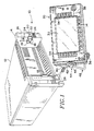
- FIG. 1 an electronic instrument 10 is shown having a main chassis 12 within which the electronics of the electronic instrument are contained.
- a front frame 14 is mounted to the front of the main chassis 12, the front frame having a relatively deep recess 16 exposed to the front and having opposing cutouts 18 on opposing internal faces of the recess.
- a latch 20 is fixedly mounted to the main chassis 12 at one end, with the other end having a ramp 22 and funnel 24 configuration extending through the cutout 18 so that it is exposed within and extends exterior to the recess 16 at the front edge.
- a display module 30, having a flat panel display 32 with recessed control buttons 34 surrounding the display, is electrically connected with the main chassis 12 via a detachable electrical cable 36 that connects to an electrical port 26 of the instrument 10.
- the display module 30 has a front panel section 38 and a back panel section 40 that mate with a tongue and groove joint to provide EMI shielding to the interior of the display module 30.
- Integral with the front panel section 38 are opposing ears 42 that align with the latches 20 when the display module 30 is installed within the front frame 14.
- Rotatably mounted on each ear 42 is a friction clutch assembly 44 that has a hub 46 with a configuration that closely matches a corresponding depression 28 in the latch 20.
- Integral with the clutch assembly 44 is a stand 48 so that the display module 30 may be free standing and tiltable when remoted from the electronic instrument 10.
- the stand 48 also serves to keep the opposing clutch assemblies 44 rotationally aligned with each other.
- the display module 30 is inserted into the chassis by aligning one hub 46 with its corresponding latch depression 28 and then sliding the opposing hub up the ramp 22, guided by the funnel 24, until it engages the opposing latch depression.
- the display module 30 may be tilted within the recess 16 by applying sufficient force to either the upper or lower edge of the front panel 38 to overcome the friction of the clutch assemblies 44.
- the angular tilt is limited only by the depth of the recess 16, and tilts of +/-30 o are obtainable.
- To release the display module 30 one of the clutch assemblies 44 is disengaged from its corresponding latch 20 by pressing outwardly on the ramp 22 and that end of the display module is slid out.
- An integral handle 50 in the back panel section 40 allows for easy one-handed operation and carrying of the display module 30.
- the friction of the clutch assemblies 44 is sufficient to allow operation of the control buttons 34 by an operator without changing the tilt of the display module 30 when the display module is mounted within the front frame 14.
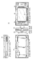
- the front frame 14 is shown in greater detail in Fig. 2.
- the cutout 18 is configured to match the depression 28 in the latch 20 and the hub 46 of the clutch assembly 44.
- the cutout 18 supports the display module 30 while the latch 20 retains it in the main chassis 12.
- a land 19 is built up internal to the recess 16 and partially surrounds the cutout 18, encompassing the back and a portion of each side.
- the front portion 15 of the land 19 is tapered inwardly toward the cutout 18 to match the funnel 24 configuration of the latch 20.
- the front frame 14 also includes air vents 17 to provide cooling for the display module 30 when mounted in the front frame.
- the latch 20 as shown in greater detail in Fig. 3, has a mounting end 21 for fixedly attaching the latch to the main chassis 12.
- the latch is of a relatively stiff material so that when the ramp end 22 is depressed under pressure, the latch returns to its original position when the pressure is removed. Slots 23 in the latch 20 near the attachment end 21 provide a less rigid portion of the latch where the maximum bending of the latch under pressure occurs.
- An integral support bar 25 provides additional strength and stiffening of the latch 20 at the ramp end 22. As stated above the configuration of the back edge 27 of the funnel 24 matches the front end 15 of the land 19 in the front frame 14.
- the clutch assembly 44 has an interior casing 52, an exterior casing 54 that includes the hub 46, and a spring 56, as shown in Fig. 4.
- the interior casing 52 is in the form of a shallow cap, or a disc, with a central depression 58 on one side. Within the central depression 58 are diametrical raised ribs 60 with a central circular portion 62 having a central hole 64. The opposite side of the central circular portion 62 has a countersunk depression (not shown) about the central hole 64.
- the exterior casing 54 has a tubular main portion 66 with slits 68 in the interior end that engage the raised ribs 60 of the interior casing 52. Along the axis of the tubular portion 66, as shown in Fig.
- a post 70 having a centrally threaded hole 72, the threaded hole being aligned with the central hole 64 of the interior case 52 when the interior and exterior cases are joined.
- Surrounding the tube 66 is an integral flange portion 74 that seals the exterior end of the tube, the hub 46 being an integral portion of the exterior part of the flange portion.
- a circular groove 76 in the interior part of the flange portion 74 surrounds the circumference of the tube 66. The groove 76 engages an opposing rim surrounding a hole 80 on the ear 42 of the front panel 38.
- the tubular portion 66 of the exterior casing 54 extends through the hole 80 in the ear portion 42 of the front panel 38 and engages the interior of the central depression 58 of the interior casing 52, with the slits 68 encompassing the ribs 60.
- the annular wave spring 56 Around the tube 66 is placed the annular wave spring 56.
- a screw 78 is inserted through the central hole 64 to threadedly engage the threaded hole 72 of the exterior casing 54 to securely hold the clutch assembly 44 together.
- the length of the tube 66 is determined so that the spring 56 is held against the display module 30 with sufficient friction to prevent movement when an operator touches the control buttons, but not so tight as to require too great a force to tilt the display module within the recess.
- the head of the screw 78 fits within the countersunk hole of the interior casing 52.
- the front panel 38 has the integral ear 42 with the hole 80 through which the tubular portion 66 of the exterior casing 54 of the clutch assembly 44 extends to engage the interior casing 52.
- An exterior bearing surface 82 of the ear 42 surrounding the hole 80 provides the surface against which the flange 74 exerts its frictional pressure on the exterior while the spring 56 exerts pressure on the interior annular surface.
- a groove 84 completely surrounds the back edge of the front panel 38, and the back panel 40 has a corresponding tongue to engage the groove to provide a sealed, EMI resistant display module 30 when the two panels are joined by suitable means.
- the present invention provides a multi-purpose display module for an electrical instrument that may be rotatably mounted within a recess at the front of the instrument to allow the display module to be tilted to any desirable angle, the mounting being in the form of a cantilever latch mounted on the instrument and extending into the recess, the latch retaining the display module in the instrument while the recess supports it.
- the latch has a depression that matches a hub on a clutch assembly mounted on the display module. By releasing the latch the display module may be removed from the instrument and set up on an integral stand remote from the instrument, the electrical connection between the instrument and the display module being maintained by an electrical cable of suitable length.
Landscapes
- Engineering & Computer Science (AREA)
- Computer Networks & Wireless Communication (AREA)
- Signal Processing (AREA)
- Devices For Indicating Variable Information By Combining Individual Elements (AREA)
- Mounting Of Printed Circuit Boards And The Like (AREA)
Applications Claiming Priority (2)
| Application Number | Priority Date | Filing Date | Title |
|---|---|---|---|
| US07/417,354 US4964018A (en) | 1989-10-05 | 1989-10-05 | Multi-purpose display module system for an electronic instrument |
| US417354 | 1995-04-05 |
Publications (3)
| Publication Number | Publication Date |
|---|---|
| EP0421630A2 true EP0421630A2 (fr) | 1991-04-10 |
| EP0421630A3 EP0421630A3 (en) | 1991-08-14 |
| EP0421630B1 EP0421630B1 (fr) | 1994-01-05 |
Family
ID=23653654
Family Applications (1)
| Application Number | Title | Priority Date | Filing Date |
|---|---|---|---|
| EP90310207A Expired - Lifetime EP0421630B1 (fr) | 1989-10-05 | 1990-09-18 | Système à usage multiple de module d'affichage pour un instrument électronique |
Country Status (4)
| Country | Link |
|---|---|
| US (1) | US4964018A (fr) |
| EP (1) | EP0421630B1 (fr) |
| JP (1) | JPH03129799A (fr) |
| DE (1) | DE69005774T2 (fr) |
Cited By (3)
| Publication number | Priority date | Publication date | Assignee | Title |
|---|---|---|---|---|
| EP0737908A1 (fr) * | 1995-04-12 | 1996-10-16 | Hewlett-Packard Company | Système d'ordinateur avec dispositif d'affichage interactif commandé à distance |
| EP0813136A3 (fr) * | 1996-05-13 | 2003-07-16 | Nematron Corporation | Poste de travail informatique industrielle |
| TWI461140B (zh) * | 2011-03-30 | 2014-11-11 | Inventec Corp | 可攜式電子裝置 |
Families Citing this family (35)
| Publication number | Priority date | Publication date | Assignee | Title |
|---|---|---|---|---|
| US5268816A (en) * | 1982-09-28 | 1993-12-07 | Lexmark International, Inc. | Movable display screen for a computer |
| FR2655212B1 (fr) * | 1989-11-29 | 1992-11-20 | Alcatel Transmission | Structure verticale compatible electromagnetiquement pour systeme d'exploitation d'un equipement de transmission, notamment par faisceaux hertziens. |
| US5229925A (en) * | 1991-07-19 | 1993-07-20 | Valcom, Inc. | Modular front panel and enclosure for electronic apparatus |
| JPH0536423U (ja) * | 1991-10-18 | 1993-05-18 | アンリツ株式会社 | 表示装置 |
| JPH05297284A (ja) * | 1992-04-20 | 1993-11-12 | Olympus Optical Co Ltd | 工業用内視鏡装置 |
| FR2692098B1 (fr) * | 1992-06-04 | 1994-07-22 | Alcatel Radiotelephone | Appareil electronique transformable pour montage mural ou en baie. |
| DE4221024C2 (de) * | 1992-06-26 | 1995-11-30 | Ruf Kg Wilhelm | Haltevorrichtung zur Lagerung eines durch eine drehbare Welle betätigbaren elektrischen Bauteils an einem Gegenstand |
| US5235495A (en) * | 1992-09-21 | 1993-08-10 | Telepad Corporation | Pen-based computer with handle/prop having ratchet locking mechanism |
| US5288049A (en) * | 1992-10-13 | 1994-02-22 | Hays Robert E | Secured monitor mounting bracket |
| US5724069A (en) * | 1994-07-15 | 1998-03-03 | Chen; Jack Y. | Special purpose terminal for interactive user interface |
| US5761045A (en) * | 1995-12-22 | 1998-06-02 | Apple Computer, Inc. | Modular, redundant, hot swappable, blind mate power supply system |
| US5805415A (en) * | 1996-10-03 | 1998-09-08 | Hewlett-Packard Company | Detachable flat panel computer display and support |
| US5949640A (en) * | 1997-08-19 | 1999-09-07 | Statpower Technologies Corp. | Power inverter with re-orientable display panel and AC port modules |
| DE19817945C1 (de) * | 1998-04-17 | 1999-11-18 | Siemens Ag | Schrank mit mindestens einem eingebauten elektrischen Gerät |
| US6185110B1 (en) * | 1999-01-29 | 2001-02-06 | Jin Liu | Mounting frame for mounting input/output device to conpactPCI-based computer |
| US6388878B1 (en) * | 2000-08-14 | 2002-05-14 | Cheng-Chun Chang | Measuring device in a mobile rack for hard disk |
| US6724635B2 (en) * | 2001-08-07 | 2004-04-20 | Hewlett-Packard Development Company, L.P. | LCD panel for a server system |
| EP1579747B1 (fr) * | 2003-01-03 | 2007-03-28 | Rhode & Schwarz GmbH & Co. Kg | Modules d'appareil de mesure et appareil de mesure |
| US7102592B2 (en) * | 2003-06-26 | 2006-09-05 | Compal Electronics, Inc. | Video signal converter for a detachable display module of a portable computer |
| US20050204596A1 (en) * | 2004-03-18 | 2005-09-22 | Peng Juen T | Portable seat back display |
| WO2005104762A2 (fr) * | 2004-04-28 | 2005-11-10 | Michael Krieger | Systeme d'alimentation electrique mobile |
| FR2870084B1 (fr) * | 2004-05-04 | 2006-06-16 | Schneider Toshiba Inverter | Variateur electronique de vitesse a agencement modulaire |
| KR101175728B1 (ko) * | 2006-01-20 | 2012-08-22 | 삼성전자주식회사 | 디스플레이 모듈의 전자파 차폐장치 및 그 제조방법 |
| US20070298706A1 (en) * | 2006-06-22 | 2007-12-27 | Springfield Precision Instruments, Inc. | Programmable energy saving register vent |
| JP4814761B2 (ja) * | 2006-11-15 | 2011-11-16 | 光洋電子工業株式会社 | 小型表示器を備えた表示器装置 |
| KR100724583B1 (ko) * | 2007-04-04 | 2007-06-04 | (주)프로콤 | 송수신부와 제어부가 분리 가능한 생활용 무전기 |
| US7612988B2 (en) * | 2007-04-05 | 2009-11-03 | Satin America Corporation | Switchgear with movable user interface module |
| US8079267B2 (en) * | 2007-07-31 | 2011-12-20 | Agilent Technologies, Inc. | Systems and methods for conducting simultaneous vibration and electrical testing |
| US8776358B2 (en) | 2007-08-06 | 2014-07-15 | Apple Inc. | Housing components for electronic devices |
| CN102053664A (zh) * | 2009-11-09 | 2011-05-11 | 鸿富锦精密工业(深圳)有限公司 | 电脑主机及其机箱 |
| US20110188197A1 (en) * | 2010-02-03 | 2011-08-04 | Craig Jackson | Integrated audio and video port for portable electonic devices |
| USD741268S1 (en) * | 2013-11-04 | 2015-10-20 | Maschinenfabrik Reinhausen Gmbh | Face panel for rack-mount controller |
| CN105690382A (zh) * | 2014-12-12 | 2016-06-22 | 精工爱普生株式会社 | 机器人控制装置 |
| DE102020108528A1 (de) | 2020-03-27 | 2021-09-30 | GMC-I Messtechnik GmbH | Messgerätanordnung umfassend eine Messgerätvorrichtung zur Messung elektrischer Messgrößen |
| CN112373303B (zh) * | 2020-10-13 | 2024-01-05 | 速珂智能科技(上海)有限公司 | 一种带gprs通讯以及报警器功能的显示仪表 |
Family Cites Families (9)
| Publication number | Priority date | Publication date | Assignee | Title |
|---|---|---|---|---|
| US2566064A (en) * | 1946-10-21 | 1951-08-28 | Gen Electric | Cabinet construction |
| US3856450A (en) * | 1972-11-06 | 1974-12-24 | Manbritt Ind Inc | Mold construction |
| US3831128A (en) * | 1973-07-23 | 1974-08-20 | Reliable Electric Co | Rotatable terminal block |
| US4231115A (en) * | 1978-11-27 | 1980-10-28 | General Aviation Electronics, Inc. | Modular radio |
| DE7908550U1 (de) * | 1979-03-27 | 1979-07-12 | Viessmann, Hans, 3559 Battenberg | Gehaeuse fuer insbesondere multivalente heizungsregelungen |
| US4667271A (en) * | 1982-09-16 | 1987-05-19 | Ampex Corporation | Adjustable front control panel for a tape transport component arrangement |
| DE3330587C2 (de) * | 1983-08-25 | 1986-09-18 | Rohde & Schwarz GmbH & Co KG, 8000 München | An einem Meßplatz in unterschiedlicher Höhe vor einem Benutzer abstellbares elektronisches Meßgerät |
| GB2150726B (en) * | 1983-11-30 | 1988-01-20 | Standard Telephones Cables Ltd | Office terminals |
| US4625259A (en) * | 1984-04-12 | 1986-11-25 | Prentice Corporation | Integral pivoting power supply |
-
1989
- 1989-10-05 US US07/417,354 patent/US4964018A/en not_active Expired - Fee Related
-
1990
- 1990-09-18 DE DE90310207T patent/DE69005774T2/de not_active Expired - Fee Related
- 1990-09-18 EP EP90310207A patent/EP0421630B1/fr not_active Expired - Lifetime
- 1990-10-04 JP JP2267428A patent/JPH03129799A/ja active Pending
Cited By (4)
| Publication number | Priority date | Publication date | Assignee | Title |
|---|---|---|---|---|
| EP0737908A1 (fr) * | 1995-04-12 | 1996-10-16 | Hewlett-Packard Company | Système d'ordinateur avec dispositif d'affichage interactif commandé à distance |
| US5850209A (en) * | 1995-04-12 | 1998-12-15 | Hewlett-Packard Company | Computer system having remotely operated interactive display |
| EP0813136A3 (fr) * | 1996-05-13 | 2003-07-16 | Nematron Corporation | Poste de travail informatique industrielle |
| TWI461140B (zh) * | 2011-03-30 | 2014-11-11 | Inventec Corp | 可攜式電子裝置 |
Also Published As
| Publication number | Publication date |
|---|---|
| EP0421630A3 (en) | 1991-08-14 |
| EP0421630B1 (fr) | 1994-01-05 |
| US4964018A (en) | 1990-10-16 |
| JPH03129799A (ja) | 1991-06-03 |
| DE69005774D1 (de) | 1994-02-17 |
| DE69005774T2 (de) | 1994-04-28 |
Similar Documents
| Publication | Publication Date | Title |
|---|---|---|
| US4964018A (en) | Multi-purpose display module system for an electronic instrument | |
| US6522529B1 (en) | Rotatable computer display apparatus and method | |
| US5119203A (en) | Monitor mounting fixture | |
| US6570627B1 (en) | Flat-type monitor | |
| US4759225A (en) | Torque tool and torque tool analyzer | |
| US4831736A (en) | Carriage for a computer mouse | |
| JP4495284B2 (ja) | ディスプレイ支持装置 | |
| US5168429A (en) | Electronic apparatus having a slidable pawl for removably connecting a display housing to a base housing | |
| CN105518757B (zh) | 云台遥控器及采用该云台遥控器的手持云台 | |
| US20090256970A1 (en) | Teleprompter | |
| EP0705563A1 (fr) | Dispositif destiné à la surveillance de la pression sanguine | |
| US4590378A (en) | Counterbalanced radiation detection device | |
| US5360194A (en) | Support assembly for optical equipment | |
| US4036459A (en) | Instrument swivel bracket | |
| US4683465A (en) | Data display terminal using a flat display panel | |
| CN221054715U (zh) | 脚架 | |
| CN218974144U (zh) | 一种高精密探针用检测装置 | |
| CN214335213U (zh) | 一种超声波距离探测仪 | |
| JPH0329722Y2 (fr) | ||
| US20060226307A1 (en) | Display apparatus | |
| CN215000422U (zh) | 一种相机云台调整结构 | |
| CN210347655U (zh) | 一种可拆装面板结构及血气分析仪 | |
| CN214583348U (zh) | 一种具备调节功能的环境质量检测设备 | |
| CN211749670U (zh) | 一种便携式c型臂系统 | |
| CN215066216U (zh) | 一种具有高倍高清电子显微镜系统的土壤检测仪 |
Legal Events
| Date | Code | Title | Description |
|---|---|---|---|
| PUAI | Public reference made under article 153(3) epc to a published international application that has entered the european phase |
Free format text: ORIGINAL CODE: 0009012 |
|
| AK | Designated contracting states |
Kind code of ref document: A2 Designated state(s): CH DE FR GB LI NL |
|
| PUAL | Search report despatched |
Free format text: ORIGINAL CODE: 0009013 |
|
| AK | Designated contracting states |
Kind code of ref document: A3 Designated state(s): CH DE FR GB LI NL |
|
| 17P | Request for examination filed |
Effective date: 19920213 |
|
| 17Q | First examination report despatched |
Effective date: 19920603 |
|
| GRAA | (expected) grant |
Free format text: ORIGINAL CODE: 0009210 |
|
| AK | Designated contracting states |
Kind code of ref document: B1 Designated state(s): CH DE FR GB LI NL |
|
| PG25 | Lapsed in a contracting state [announced via postgrant information from national office to epo] |
Ref country code: NL Effective date: 19940105 Ref country code: LI Effective date: 19940105 Ref country code: FR Effective date: 19940105 Ref country code: CH Effective date: 19940105 |
|
| REF | Corresponds to: |
Ref document number: 69005774 Country of ref document: DE Date of ref document: 19940217 |
|
| REG | Reference to a national code |
Ref country code: CH Ref legal event code: PL |
|
| EN | Fr: translation not filed | ||
| NLV1 | Nl: lapsed or annulled due to failure to fulfill the requirements of art. 29p and 29m of the patents act | ||
| PLBE | No opposition filed within time limit |
Free format text: ORIGINAL CODE: 0009261 |
|
| STAA | Information on the status of an ep patent application or granted ep patent |
Free format text: STATUS: NO OPPOSITION FILED WITHIN TIME LIMIT |
|
| 26N | No opposition filed | ||
| PGFP | Annual fee paid to national office [announced via postgrant information from national office to epo] |
Ref country code: GB Payment date: 19960820 Year of fee payment: 7 |
|
| PGFP | Annual fee paid to national office [announced via postgrant information from national office to epo] |
Ref country code: DE Payment date: 19960824 Year of fee payment: 7 |
|
| PG25 | Lapsed in a contracting state [announced via postgrant information from national office to epo] |
Ref country code: GB Free format text: LAPSE BECAUSE OF NON-PAYMENT OF DUE FEES Effective date: 19970918 |
|
| GBPC | Gb: european patent ceased through non-payment of renewal fee |
Effective date: 19970918 |
|
| PG25 | Lapsed in a contracting state [announced via postgrant information from national office to epo] |
Ref country code: DE Free format text: LAPSE BECAUSE OF NON-PAYMENT OF DUE FEES Effective date: 19980603 |