EP0421800A2 - "RTM"-Verarbeitungsanlage und Verfahren - Google Patents
"RTM"-Verarbeitungsanlage und Verfahren Download PDFInfo
- Publication number
- EP0421800A2 EP0421800A2 EP90310906A EP90310906A EP0421800A2 EP 0421800 A2 EP0421800 A2 EP 0421800A2 EP 90310906 A EP90310906 A EP 90310906A EP 90310906 A EP90310906 A EP 90310906A EP 0421800 A2 EP0421800 A2 EP 0421800A2
- Authority
- EP
- European Patent Office
- Prior art keywords
- mould
- shell
- frame
- halves
- mould half
- Prior art date
- Legal status (The legal status is an assumption and is not a legal conclusion. Google has not performed a legal analysis and makes no representation as to the accuracy of the status listed.)
- Granted
Links
- 238000000034 method Methods 0.000 title abstract description 8
- 238000009745 resin transfer moulding Methods 0.000 title abstract description 7
- 238000000465 moulding Methods 0.000 claims abstract description 21
- 229920005989 resin Polymers 0.000 claims abstract description 15
- 239000011347 resin Substances 0.000 claims abstract description 15
- 230000007246 mechanism Effects 0.000 claims abstract description 10
- 238000010438 heat treatment Methods 0.000 description 12
- 238000002347 injection Methods 0.000 description 6
- 239000007924 injection Substances 0.000 description 6
- 238000010276 construction Methods 0.000 description 4
- 125000006850 spacer group Chemical group 0.000 description 4
- 229910000831 Steel Inorganic materials 0.000 description 3
- 239000000463 material Substances 0.000 description 3
- 238000000926 separation method Methods 0.000 description 3
- 239000010959 steel Substances 0.000 description 3
- 230000000295 complement effect Effects 0.000 description 2
- 238000001816 cooling Methods 0.000 description 2
- 239000011152 fibreglass Substances 0.000 description 2
- 239000007788 liquid Substances 0.000 description 2
- 238000004519 manufacturing process Methods 0.000 description 2
- 230000002093 peripheral effect Effects 0.000 description 2
- 229920002430 Fibre-reinforced plastic Polymers 0.000 description 1
- 239000000853 adhesive Substances 0.000 description 1
- 230000001070 adhesive effect Effects 0.000 description 1
- 239000004411 aluminium Substances 0.000 description 1
- 229910052782 aluminium Inorganic materials 0.000 description 1
- XAGFODPZIPBFFR-UHFFFAOYSA-N aluminium Chemical compound [Al] XAGFODPZIPBFFR-UHFFFAOYSA-N 0.000 description 1
- 230000001276 controlling effect Effects 0.000 description 1
- 239000012809 cooling fluid Substances 0.000 description 1
- 239000000498 cooling water Substances 0.000 description 1
- 230000003247 decreasing effect Effects 0.000 description 1
- 238000010586 diagram Methods 0.000 description 1
- 239000003822 epoxy resin Substances 0.000 description 1
- 239000011151 fibre-reinforced plastic Substances 0.000 description 1
- 239000002657 fibrous material Substances 0.000 description 1
- 239000012467 final product Substances 0.000 description 1
- 239000012530 fluid Substances 0.000 description 1
- 239000003365 glass fiber Substances 0.000 description 1
- 238000007654 immersion Methods 0.000 description 1
- 229910052751 metal Inorganic materials 0.000 description 1
- 239000002184 metal Substances 0.000 description 1
- 239000004033 plastic Substances 0.000 description 1
- 229920003023 plastic Polymers 0.000 description 1
- 229920000647 polyepoxide Polymers 0.000 description 1
- 239000000047 product Substances 0.000 description 1
- 230000001105 regulatory effect Effects 0.000 description 1
- 239000012779 reinforcing material Substances 0.000 description 1
- 230000000717 retained effect Effects 0.000 description 1
- 239000007787 solid Substances 0.000 description 1
- 229920001187 thermosetting polymer Polymers 0.000 description 1
- 238000013022 venting Methods 0.000 description 1
- XLYOFNOQVPJJNP-UHFFFAOYSA-N water Substances O XLYOFNOQVPJJNP-UHFFFAOYSA-N 0.000 description 1
Images






Classifications
-
- B—PERFORMING OPERATIONS; TRANSPORTING
- B29—WORKING OF PLASTICS; WORKING OF SUBSTANCES IN A PLASTIC STATE IN GENERAL
- B29C—SHAPING OR JOINING OF PLASTICS; SHAPING OF MATERIAL IN A PLASTIC STATE, NOT OTHERWISE PROVIDED FOR; AFTER-TREATMENT OF THE SHAPED PRODUCTS, e.g. REPAIRING
- B29C70/00—Shaping composites, i.e. plastics material comprising reinforcements, fillers or preformed parts, e.g. inserts
- B29C70/04—Shaping composites, i.e. plastics material comprising reinforcements, fillers or preformed parts, e.g. inserts comprising reinforcements only, e.g. self-reinforcing plastics
- B29C70/28—Shaping operations therefor
- B29C70/40—Shaping or impregnating by compression not applied
- B29C70/42—Shaping or impregnating by compression not applied for producing articles of definite length, i.e. discrete articles
- B29C70/46—Shaping or impregnating by compression not applied for producing articles of definite length, i.e. discrete articles using matched moulds, e.g. for deforming sheet moulding compounds [SMC] or prepregs
- B29C70/48—Shaping or impregnating by compression not applied for producing articles of definite length, i.e. discrete articles using matched moulds, e.g. for deforming sheet moulding compounds [SMC] or prepregs and impregnating the reinforcements in the closed mould, e.g. resin transfer moulding [RTM], e.g. by vacuum
-
- B—PERFORMING OPERATIONS; TRANSPORTING
- B29—WORKING OF PLASTICS; WORKING OF SUBSTANCES IN A PLASTIC STATE IN GENERAL
- B29C—SHAPING OR JOINING OF PLASTICS; SHAPING OF MATERIAL IN A PLASTIC STATE, NOT OTHERWISE PROVIDED FOR; AFTER-TREATMENT OF THE SHAPED PRODUCTS, e.g. REPAIRING
- B29C33/00—Moulds or cores; Details thereof or accessories therefor
- B29C33/20—Opening, closing or clamping
- B29C33/202—Clamping means operating on closed or nearly closed mould parts, the clamping means being independently movable of the opening or closing means
-
- B—PERFORMING OPERATIONS; TRANSPORTING
- B29—WORKING OF PLASTICS; WORKING OF SUBSTANCES IN A PLASTIC STATE IN GENERAL
- B29C—SHAPING OR JOINING OF PLASTICS; SHAPING OF MATERIAL IN A PLASTIC STATE, NOT OTHERWISE PROVIDED FOR; AFTER-TREATMENT OF THE SHAPED PRODUCTS, e.g. REPAIRING
- B29C33/00—Moulds or cores; Details thereof or accessories therefor
- B29C33/20—Opening, closing or clamping
- B29C33/22—Opening, closing or clamping by rectilinear movement
- B29C33/24—Opening, closing or clamping by rectilinear movement using hydraulic or pneumatic means
-
- B—PERFORMING OPERATIONS; TRANSPORTING
- B29—WORKING OF PLASTICS; WORKING OF SUBSTANCES IN A PLASTIC STATE IN GENERAL
- B29C—SHAPING OR JOINING OF PLASTICS; SHAPING OF MATERIAL IN A PLASTIC STATE, NOT OTHERWISE PROVIDED FOR; AFTER-TREATMENT OF THE SHAPED PRODUCTS, e.g. REPAIRING
- B29C33/00—Moulds or cores; Details thereof or accessories therefor
- B29C33/56—Coatings, e.g. enameled or galvanised; Releasing, lubricating or separating agents
-
- B—PERFORMING OPERATIONS; TRANSPORTING
- B30—PRESSES
- B30B—PRESSES IN GENERAL
- B30B15/00—Details of, or accessories for, presses; Auxiliary measures in connection with pressing
- B30B15/007—Means for maintaining the press table, the press platen or the press ram against tilting or deflection
-
- B—PERFORMING OPERATIONS; TRANSPORTING
- B30—PRESSES
- B30B—PRESSES IN GENERAL
- B30B15/00—Details of, or accessories for, presses; Auxiliary measures in connection with pressing
- B30B15/16—Control arrangements for fluid-driven presses
- B30B15/24—Control arrangements for fluid-driven presses controlling the movement of a plurality of actuating members to maintain parallel movement of the platen or press beam
-
- B—PERFORMING OPERATIONS; TRANSPORTING
- B29—WORKING OF PLASTICS; WORKING OF SUBSTANCES IN A PLASTIC STATE IN GENERAL
- B29C—SHAPING OR JOINING OF PLASTICS; SHAPING OF MATERIAL IN A PLASTIC STATE, NOT OTHERWISE PROVIDED FOR; AFTER-TREATMENT OF THE SHAPED PRODUCTS, e.g. REPAIRING
- B29C33/00—Moulds or cores; Details thereof or accessories therefor
- B29C33/34—Moulds or cores; Details thereof or accessories therefor movable, e.g. to or from the moulding station
- B29C33/36—Moulds or cores; Details thereof or accessories therefor movable, e.g. to or from the moulding station continuously movable in one direction, e.g. in a closed circuit
Definitions
- This invention relates to moulding equipment, particularly resin transfer moulding equipment.
- a mould cavity is formed from two separable mould halves. Plastics material is introduced into the mould cavity and allowed to cure. The two mould halves are then separated to allow removal of the cured moulding.
- resin transfer moulding a dry preform of fibrous material, such as glass fibre, is first loaded into the mould cavity and liquid thermosetting resin is used to impregnate the preform and to form the final product.
- GB-1353746 discloses equipment for producing fibreglass mouldings in which a pair of dies are held in a desired relative position so as to define a moulding cavity by means of steel frames which give rigidity to the dies.
- a mat of fibreglass is loaded into the mould cavity, the dies are clamped together and resin is injected into the cavity through an injection socket positioned centrally in one of the dies.
- Resin is supplied from a tanks which may be mounted on a trolley or carriage for movement from mould to mould to facilitate line production.
- Each mould is custom-built for each product, and, being separated from the resin injection system, is unsuitable for high speed production.
- US-3380117 and US-3473196 disclose automatic moulding machines in which two mould halves are mounted in a frame for movement vertically into and out of a closed position in which they define a mould cavity into which moulding material may be introduced from a transfer system mounted on the machine.
- An hydraulic cylinder is used to lower the upper mould half, and pressure in the cylinder maintains the two mould halves in contact during the moulding operation.
- GB-2158389 and GB-2064415 disclose moulding equipment in which the two mould halves are mounted on platens that are slidable horizontally on a frame towards and away from a closed position by means of hydraulic cylinders.
- the platens carry clamps for locking the two mould halves together in the closed position.
- actuation of the clamps increases the closing forces between the twc mould halves.
- resin transfer moulding equipment comprises a frame, first and second mould halves mounted in the frame, means for moving the mould halves into and out of a closed position in which they define a mould cavity into which resin may be introduced, and means for clamping the mould halves together in the closed position, the means for moving mould halves being disengagable from the mould halves when the clamping means is engaged.
- the means for moving the mould halves offers no resistance to the clamping means, thereby facilitating an accurate alignment of the mould halves in their closed position.
- the means for moving the mould halves comprises at least one lifting jack moveable into engagement with the second mould half to raise it relative to the first mould half.
- a drive mechanism is preferably included for transferring movement from one lifting jack to the other lifting jack or jacks.
- the lifting jacks facilitate the separation of the mould halves, and the drive mechanism ensures that the separation occurs evenly, which also contributes to a reduction in cycle time for the moulding process.
- the frame preferably comprises a plurality of upright pillars on each of which is mounted a carriage capable of travelling along the pillar, and each carriage is connected to the second mould and to a respective one of the lifting jacks.
- the drive mechanism preferably comprises chain drives mounted on the frame and interconnecting the carriages.
- each mould half comprising a shell defining a mould surface and a support for the shell, the support being sufficiently rigid to prevent deformation of the shell during the moulding process.
- the shells are removably mounted on the supports so that the same equipment can be used to produce different mouldings simply by interchanging the shells.
- the first mould half may be mounted on one or more stands the height of which is adjustable.
- the first mould half may be mounted for movement out of the frame, for example on rollers, for replacement by another mould half carrying a different shell.
- the shells of at least one mould half, and preferably both, may comprise means for heating the mould surface, for example in the form of a plurality of heating elements and means for controlling individually the temperatures of the heating elements.
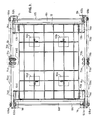
- resin transfer moulding equipment comprises a frame defined by four hollow rolled steel upright pillars 1a-d of rectangular cross-section secured at their feet to a concrete bed 5 and bolted at their upper ends to an H-frame composed of four hollow rolled steel cross-members 6a-d.
- a first mould half 8 is fixed to the bed 5 by four stands 10a-d.
- Each stand comprises two X-section beams bolted together and upright L-section locating element mounted on the top of each of the upper beams 10.
- the height of the first mould half 8 above the bed 5 can be adjusted by removing one or both the beams in each stand, or by inserting shims (not shown) between the stands and the first mould half 8.
- a second mould half 12 is housed within the frame for vertical movement towards and away from the first mould half, as indicated by solid and broken lines in Figures 1 and 2.
- Each corner of the second mould half 12 carries a mounting bracket 13a-d.
- Carriage pins 14a-d project laterally from each bracket and rest in a respective one of four carriages 15a-d, each of which can travel up and down the pillars 1a-d.
- Each carriage is retained in its raised position by a latch mechanism, one of which is illustrated in detail in Figure 18, comprising a bolt 3 mounted within the upright pillar 1 for movement between an extended position, in which it projects through an aperture in the pillar 1 to engage the lower edge of the carriage 15, and a retracted position.
- the bolt 3 is biased into the extended position by a spring 4,and may be retracted by a pneumatic cylinder 7.
- the lower leading edge of the bolt 3 is chamfered so that upward movement of the carriage 15 past the bolt drives the bolt into the retracted position.
- the two mould halves 8,12 are of similar construction, each comprising a series of vertical metal plates arranged in a rectangular grid which forms a rigid support 9,11 for a shell 17, 18, which are illustrated in more detail in Figures 4 to 9.
- the shell 17 of the first mould half is illustrated in Figures 4 to 7.
- the shell is a rectangular plaque mould suitable for producing flat panels of fibre-reinforced plastics material measuring 4mm x 100cm x150 cm.
- Other configurations of shell can of course be used to produce articles of different shapes.
- Non-planar shells would be mounted on a supporting structure preferably in the form c,f a frame complementary in shape to the reverse face of tle shell, and secured to the support 9, 11.
- the shell 17 has a chromium-plated upper moulding surface 19 and a peripheral rectangular recesses or gallery for receiving a spacer element 20, and a seal 21, as best seen in Figure 5.
- the peripheral recess is provided with apertures 22 (see Figure 6) through the shell at regular intervals, and the spacer and seal 20,21 are configured to expose one or more of the apertures to permit venting of the mould in use.
- Further apertures 23,23 along the centre lines of the shell 17 are provided for the injection of resin into the mould or for measuring instruments, such as thermocouples or transducers.
- the rear surface of the shell 17 is provided with a series of parallel grooves 24 each of which receives a tubular heating element (not shown) through which heated fluid, such as oil, at a predetermined temperature can be passed.
- the heating elements are secured in the recesses by a heat-conducting adhesive, such as an aluminium-filled epoxy resin. The flow of heating or cooling fluid through the heating elements can be controlled so that any required temperature gradient can be established across the shell.
- the shell 18 for the second mould half 12 is illustrated in Figures 8 and 9.
- This shell is also a rectangular plaque mould having a plane chromium-plated lower moulding surface 25 and a rear surface having parallel recesses 26 for tubular heating elements.
- a series of apertures 27 arranged on the lateral and longitudinal centre line of the shell are provided for the injection of resin.
- Sensors such as thermocouples. and pressure transducers (not shown) may be attached to the shells to enable the progress of the injection process to be monitored.
- Both shells 17,18 are provided with bolt holes to permit the shells to be bolted to the supports.
- the heating system for the shells 17 is illustrated in more detail in Figure 20.
- a similar system is provided for the other shell 18.
- oil is held in a reservoir 150 which contains a heat exchange element 151 through which cooling water can be circulated.
- the flow of water through the heat exchange element is regulated by a thermostatically-controlled valve 153.
- Oil is pumped from the reservoir by a pump 155 along a supply line 156 over an electrically-operated immersion heater 157 and into the array of heating elements 158 in the shell 17. Each element may be opened and closed by a valve 159 so that a desired temperature gradient may be established across the mould surface. Oil emerging from the heating elements is returned to the pump for re-circulation along a return line 160, excess oil being returned via a pump relief line 161. Both the return line 160 and the pump relief line 161 contain check valves 163,164. Hot oil may be returned to the reservoir from the return line through a cooling valve 165 .
- the cooling valve is opened and closed by an electronic temperature controller 166, operable in resporse to a thermostat 169 in the supply line immediately downstream of the heater 157.
- the temperature controller 166 also controls the heater 157 so that the temperature of the oil circulating in the system is either increased, by switching on the heater 157, or decreased by returning hot oil the reservoir through the valve 165.
- the carriages 15a-d are of similar construction, which is illustrated in detail in Figures 10 to 12. Each carriage comprises two parallel side plates 30,30′ disposed on two opposite sides of the upright pillar 1 along which it travels. Each plate carries two bearing plates 31,32,31′,32′ each of which overlies one of the other two sides of the pillar 1 so that the side plates and bearing plates embrace opposite sides of the pillar.
- the bearing plates 31,31′32,32′ each carry an upper roller 33, 34, 33′,34′ and a lower roller 35,36,35′,36′, which guide the carriage 15 along the pillar. Further guidance for the carriage is provided by two further vertically-spaced rollers 37,38,37′38′ mounted in bearing blocks 39,40,39′40′ on each of the side plates 30,31.
- the side plates 30,31 are bolted to upper and lower spacer bars 42,43 ( Figure 12) on one side of the pillar, and to upper and lower anchor blocks 44,45 on the other side of the pillar.
- the inwardly-facing edges of the side plates 30,31 are also bolted to a bracket 46 (Fig 13) which is provided with a semi-circular recess for receiving one of the carriage pins 14 on the second mould half 12.Each carriage 15a-d may be moved along the upright pillar 1 by one of four lifting jacks 50a-d of similar construction.
- each jack is pivotally connected to the foot of the pillar l (as illustrated in detail with respect to one jack 50a in Figure 15), the upper end of each jack is bolted to the bottom of the bracket 46 on the carriage 15. All four lifting jacks 50a-d are operable hydraulically from a conventional hydraulic control system (not illustrated).
- the carriages 15a-d are interconnected by a drive mechanism which transfers the movement of one lifting jack to the others.
- the drive mechanism comprises four drive chains 60a-d indicated in broken lines in the drawings. Each drive chain 60a-d is connected at each end to the upper and lower anchor blocks 44,45 of one of the carriages 15a-d.
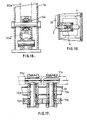
- Each drive chain 60a-d passes upwardly alongside one of the upright pillars 1a-d, over one of four first gear wheels 62a-d mounted in adjustable bearings on top of the pillars 1a-d (illustrated in detail in Figures 14 and 15), down the hollow interior of the pillar, around an idler wheel 64 mounted for rotation in the foot of the pillar 1 (illustrated in detail in Figure 16), through an aperture in the foot of the pillar and upwardly alongside the inner wall of the pillar to the lower anchor block 46 on the carriage 15. Adjustment of the bearings of the gear wheels 62a-d sets the tension in the chains 60a-d to a required level.
- the four first gear wheels 62a-d are coupled together in pairs by two drive shafts 65,66 ( Figures 1 and 2) mounted in self-aligning bearings 69 ( Figure 15) adjacent the cross members 6b and 6d and extending along opposite sides of the frame.
- the ends of the drive shafts 65,66 carry second gear wheels 68a-d.
- Each of the second gear wheels is connected by a drive chains 70a-d to one of four transfer wheels 71a-d (illustrated in detail in Figure 17) which are fixed to shafts 72a-d mounted for rotation in needle bearings towards the centres of the front and rear crossmembers 6a and 6d.
- the inner ends of the shafts 72a-d carry gear wheels 73a-d which mesh with the gear wheel on the adjacent drive shaft.
- the upper and lower mould halves 12 and 18 may be clamped together in their closed position by six clamps 80, two of which are mounted on each of the longer sides of the mould halves, one further clamp being mounted on each of the shorter sides of the mould halves, as illustrated in Figures 1 and 2.
- One clamp 80 is illustrated in more detail in Figures 19 and 20.
- the clamp comprises an upper part 81 and a lower part 82 bolted to the upper and lower mould halves 12,8 respectively.
- the lower part 82 comprises an hydraulic cylinder 85 from which a piston rod 86 projects vertically upwardly through a hollow cylindrical seat 87, which has a conical upper surface 88.
- the upper surface of the seat 87 is received within a collar 90 secured to the upper part 81 of the clamp.
- the lower surface of the collar 90 has a conical surface complementary to the upper surface of the seat 87 so that,as the mould halves close, the two parts of the clamp are guided into alignment.
- the upper end of the piston rod 86 carries a dolly 95 having a spherical head 96 and a cylindrical body 97.
- the head 96 extends into a locking ring 100 which rests on the upper part of the body 97.
- the locking ring can slide partially into the upper end of the collar 90 until a shoulder formed on the external surface of the locking ring engages the upper edge of the collar 90.
- the internal surface of the locking ring is tapered to form a conical seat.
- the upper part 81 of the clamp carries a pneumatic cylinder 110 having a piston rod that carries a collet 112.
- the lower end of the collet 112 is tapered externally to match the seat formed by the internal surface of the locking ring 100, and has a spherical internal recess for receiving the head of the dolly 95.
- Four axial slots in the end of the collet allow the collet to expand whilst the head 96 of the dolly is inserted into the collet 112.
- the shells 17, 18 are bolted to. their respective supports and, depending upon the nature of the resin to be used in the moulding process, heated to an operating temperature.
- a preform of fibrous reinforcing material is loaded into the shell 17b of the first mould half.
- the pneumatic cylinders 7 of the latch mechanisms for the carriages 15a-d are then operated to retract the bolts 7, and the lifting jacks are operated to lower the carriages and the second mould half 12 so that the moulding surface 25 of the shell of the second mould half contacts the spacers and seals 20,21 of the shell 17 on the lower mould half.
- the seats 87 of the clamps 80 engage with their respective collars 90 and align the two mould halves accurately.
- the clamps 80 are actuated.
- the hydraulic cylinder 85 is initially actuated to extend the dolly 95.
- the pneumatic piston 110 on the upper part of the clamp is actuated so that the collet 112 engages the head 96 of the dolly and the seat of the locking ring 100.
- the hydraulic cylinder 85 on the lower part of the clamp is then actuated to withdraw the piston 86 so that the locking ring slides into collar 90.
- Liquid resin is then injected into the cavity formed. by the two shells 17,18 through one or more of the apertures 23 or 27 of the shells.
- Relatively low pressure is used to inject the resin, for example 2-10 bar, typically 5 bar.
- the rigidity of the supports of the shells is sufficient to prevent distortion of the shells 17,18 during the injection of resin.
- the quality of the moulding is therefore maintained.
- the resin is allowed to cure and the lifting jacks are operated to raise the second mould half 12.
- the upward movement of each carriage 15a-d is transmitted to all the other carriages through the drive chains 60a-d and 70a-d, the drive shafts 65,66 and the gear wheels 62a-d, 68a-d and 73a-d. Consequently, even if the second mould half should stick to the first mould half during separation of the mould halves, the second mould half will be maintained in a horizontal orientation, thereby reducing the risk of damage to the moulding when the two mould halves are separated.
Landscapes
- Engineering & Computer Science (AREA)
- Mechanical Engineering (AREA)
- Chemical & Material Sciences (AREA)
- Composite Materials (AREA)
- Moulds For Moulding Plastics Or The Like (AREA)
- Injection Moulding Of Plastics Or The Like (AREA)
Applications Claiming Priority (2)
| Application Number | Priority Date | Filing Date | Title |
|---|---|---|---|
| GB898922584A GB8922584D0 (en) | 1989-10-06 | 1989-10-06 | Resin transfer moulding equipment |
| GB8922584 | 1989-10-06 |
Publications (3)
| Publication Number | Publication Date |
|---|---|
| EP0421800A2 true EP0421800A2 (de) | 1991-04-10 |
| EP0421800A3 EP0421800A3 (en) | 1991-12-11 |
| EP0421800B1 EP0421800B1 (de) | 1995-09-06 |
Family
ID=10664191
Family Applications (3)
| Application Number | Title | Priority Date | Filing Date |
|---|---|---|---|
| EP90310905A Expired - Lifetime EP0421799B1 (de) | 1989-10-06 | 1990-10-04 | "RTM"-Verarbeitungsanlage |
| EP19900310907 Expired - Lifetime EP0421801B1 (de) | 1989-10-06 | 1990-10-04 | "RTM" Verarbeitungsanlage |
| EP19900310906 Expired - Lifetime EP0421800B1 (de) | 1989-10-06 | 1990-10-04 | "RTM"-Verarbeitungsanlage und Verfahren |
Family Applications Before (2)
| Application Number | Title | Priority Date | Filing Date |
|---|---|---|---|
| EP90310905A Expired - Lifetime EP0421799B1 (de) | 1989-10-06 | 1990-10-04 | "RTM"-Verarbeitungsanlage |
| EP19900310907 Expired - Lifetime EP0421801B1 (de) | 1989-10-06 | 1990-10-04 | "RTM" Verarbeitungsanlage |
Country Status (4)
| Country | Link |
|---|---|
| EP (3) | EP0421799B1 (de) |
| DE (3) | DE69022153T2 (de) |
| ES (3) | ES2076331T3 (de) |
| GB (1) | GB8922584D0 (de) |
Families Citing this family (2)
| Publication number | Priority date | Publication date | Assignee | Title |
|---|---|---|---|---|
| US5234332A (en) * | 1991-04-01 | 1993-08-10 | The Dow Chemical Company | Molding process for multiple molds |
| GB9510496D0 (en) * | 1995-05-24 | 1995-07-19 | Ford Motor Co | Resin transfer moulding |
Family Cites Families (4)
| Publication number | Priority date | Publication date | Assignee | Title |
|---|---|---|---|---|
| US3956058A (en) * | 1974-09-13 | 1976-05-11 | Heinrich Wemhoener | Multiple-piston press for synthetic-resin coating of large surface-area workpieces |
| IT1108148B (it) * | 1978-07-11 | 1985-12-02 | Descrovi Mario | Struttura di macchina a stampaggio |
| FR2555496A1 (fr) * | 1983-11-30 | 1985-05-31 | Gruet Michel | Procede de moulage avec mise en oeuvre d'un moule perdu |
| DE3712959A1 (de) * | 1987-04-02 | 1988-10-20 | Schock & Co Gmbh | Muldenfoermiger kunststoff-sanitaergegenstand, insbesondere badewanne |
-
1989
- 1989-10-06 GB GB898922584A patent/GB8922584D0/en active Pending
-
1990
- 1990-10-04 EP EP90310905A patent/EP0421799B1/de not_active Expired - Lifetime
- 1990-10-04 ES ES90310906T patent/ES2076331T3/es not_active Expired - Lifetime
- 1990-10-04 DE DE69022153T patent/DE69022153T2/de not_active Expired - Fee Related
- 1990-10-04 EP EP19900310907 patent/EP0421801B1/de not_active Expired - Lifetime
- 1990-10-04 ES ES90310905T patent/ES2077651T3/es not_active Expired - Lifetime
- 1990-10-04 EP EP19900310906 patent/EP0421800B1/de not_active Expired - Lifetime
- 1990-10-04 DE DE69022154T patent/DE69022154T2/de not_active Expired - Fee Related
- 1990-10-04 DE DE69022156T patent/DE69022156T2/de not_active Expired - Fee Related
- 1990-10-04 ES ES90310907T patent/ES2076332T3/es not_active Expired - Lifetime
Also Published As
| Publication number | Publication date |
|---|---|
| EP0421800B1 (de) | 1995-09-06 |
| DE69022156D1 (de) | 1995-10-12 |
| EP0421799B1 (de) | 1995-09-06 |
| EP0421799A2 (de) | 1991-04-10 |
| EP0421801B1 (de) | 1995-09-06 |
| DE69022156T2 (de) | 1996-02-15 |
| ES2076331T3 (es) | 1995-11-01 |
| ES2076332T3 (es) | 1995-11-01 |
| EP0421799A3 (en) | 1992-04-15 |
| GB8922584D0 (en) | 1989-11-22 |
| DE69022153D1 (de) | 1995-10-12 |
| EP0421801A2 (de) | 1991-04-10 |
| DE69022153T2 (de) | 1996-02-15 |
| DE69022154T2 (de) | 1996-02-15 |
| EP0421800A3 (en) | 1991-12-11 |
| DE69022154D1 (de) | 1995-10-12 |
| ES2077651T3 (es) | 1995-12-01 |
| EP0421801A3 (en) | 1991-12-11 |
Similar Documents
| Publication | Publication Date | Title |
|---|---|---|
| CN206484700U (zh) | T梁液压脱模机构 | |
| DE69415263T2 (de) | Verfahren und Vorrichtung zur Schaumkunststoffherstellung | |
| CN100572021C (zh) | 一种立柱卡板锁模式液压轮胎硫化机及其调模方法 | |
| EP2886282A1 (de) | Reifenvulkanisierungsvorrichtung | |
| CN111761713B (zh) | 一种轻质墙板加工生产装置 | |
| KR910006941B1 (ko) | 다이캐스팅장치 | |
| KR101403557B1 (ko) | 성형물자동인출 및 금형 온도유지방법과 그 장치 | |
| EP0421800B1 (de) | "RTM"-Verarbeitungsanlage und Verfahren | |
| CN108237664A (zh) | 大型注射模具移模顶出系统、大型注射机不间断生产方法 | |
| DE69905329T2 (de) | Reifenvulkanisiervorrichtung | |
| CN106427011B (zh) | 一种复合材料成形机 | |
| EP2590790B1 (de) | Verfahren zum laden und entladen einer gussform auf einer schaumkunststoffformmaschine | |
| JPS63212519A (ja) | プラスチック製品、特に熱可塑性、熱硬化性およびポリウレタン高分子製品を成形するための成形機およびその方法 | |
| CN120587395A (zh) | 用于大型铸件多块大型铁型的覆砂造型线及其工作方法 | |
| CN113146940A (zh) | 用于注塑机的快速换模机构 | |
| CN201537997U (zh) | 液压式轮胎定型硫化机主机结构 | |
| CA1165081A (en) | Press and process for vulcanizing annular elements | |
| KR102365924B1 (ko) | 고무 성형용 진공 유압프레스 | |
| CN211868416U (zh) | 一种圆形pu空滤芯生产线 | |
| CN210758773U (zh) | 一种泡沫复合板的加压成型生产系统 | |
| GB2108422A (en) | Compression moulding and coating plastics sheet | |
| JP3901283B2 (ja) | パンチングプレスにおける金型交換装置 | |
| CN216682952U (zh) | 隔震橡胶支座快速脱模设备 | |
| CN216938036U (zh) | 一种真空成型设备的轨道式换模车 | |
| CN223314532U (zh) | 一种干粉成型液压机 |
Legal Events
| Date | Code | Title | Description |
|---|---|---|---|
| PUAI | Public reference made under article 153(3) epc to a published international application that has entered the european phase |
Free format text: ORIGINAL CODE: 0009012 |
|
| AK | Designated contracting states |
Kind code of ref document: A2 Designated state(s): BE CH DE ES FR GB IT LI NL SE |
|
| PUAL | Search report despatched |
Free format text: ORIGINAL CODE: 0009013 |
|
| AK | Designated contracting states |
Kind code of ref document: A3 Designated state(s): BE CH DE ES FR GB IT LI NL SE |
|
| 17P | Request for examination filed |
Effective date: 19920527 |
|
| 17Q | First examination report despatched |
Effective date: 19930721 |
|
| GRAA | (expected) grant |
Free format text: ORIGINAL CODE: 0009210 |
|
| AK | Designated contracting states |
Kind code of ref document: B1 Designated state(s): BE CH DE ES FR GB IT LI NL SE |
|
| REF | Corresponds to: |
Ref document number: 69022154 Country of ref document: DE Date of ref document: 19951012 |
|
| ITF | It: translation for a ep patent filed | ||
| REG | Reference to a national code |
Ref country code: ES Ref legal event code: FG2A Ref document number: 2076331 Country of ref document: ES Kind code of ref document: T3 |
|
| ET | Fr: translation filed | ||
| PLBE | No opposition filed within time limit |
Free format text: ORIGINAL CODE: 0009261 |
|
| STAA | Information on the status of an ep patent application or granted ep patent |
Free format text: STATUS: NO OPPOSITION FILED WITHIN TIME LIMIT |
|
| 26N | No opposition filed | ||
| REG | Reference to a national code |
Ref country code: GB Ref legal event code: 746 Effective date: 19960907 |
|
| REG | Reference to a national code |
Ref country code: FR Ref legal event code: D6 |
|
| PGFP | Annual fee paid to national office [announced via postgrant information from national office to epo] |
Ref country code: NL Payment date: 19980914 Year of fee payment: 9 |
|
| PGFP | Annual fee paid to national office [announced via postgrant information from national office to epo] |
Ref country code: SE Payment date: 19980918 Year of fee payment: 9 |
|
| PGFP | Annual fee paid to national office [announced via postgrant information from national office to epo] |
Ref country code: BE Payment date: 19980925 Year of fee payment: 9 |
|
| PGFP | Annual fee paid to national office [announced via postgrant information from national office to epo] |
Ref country code: CH Payment date: 19980929 Year of fee payment: 9 |
|
| PGFP | Annual fee paid to national office [announced via postgrant information from national office to epo] |
Ref country code: ES Payment date: 19981020 Year of fee payment: 9 |
|
| PG25 | Lapsed in a contracting state [announced via postgrant information from national office to epo] |
Ref country code: ES Free format text: LAPSE BECAUSE OF NON-PAYMENT OF DUE FEES Effective date: 19991005 |
|
| PG25 | Lapsed in a contracting state [announced via postgrant information from national office to epo] |
Ref country code: SE Free format text: THE PATENT HAS BEEN ANNULLED BY A DECISION OF A NATIONAL AUTHORITY Effective date: 19991030 |
|
| PG25 | Lapsed in a contracting state [announced via postgrant information from national office to epo] |
Ref country code: BE Free format text: LAPSE BECAUSE OF NON-PAYMENT OF DUE FEES Effective date: 19991031 Ref country code: LI Free format text: LAPSE BECAUSE OF NON-PAYMENT OF DUE FEES Effective date: 19991031 Ref country code: CH Free format text: LAPSE BECAUSE OF NON-PAYMENT OF DUE FEES Effective date: 19991031 |
|
| BERE | Be: lapsed |
Owner name: FORD MOTOR CY LTD Effective date: 19991031 |
|
| PG25 | Lapsed in a contracting state [announced via postgrant information from national office to epo] |
Ref country code: NL Free format text: LAPSE BECAUSE OF NON-PAYMENT OF DUE FEES Effective date: 20000501 |
|
| REG | Reference to a national code |
Ref country code: FR Ref legal event code: CD Ref country code: FR Ref legal event code: TP |
|
| REG | Reference to a national code |
Ref country code: CH Ref legal event code: PL |
|
| EUG | Se: european patent has lapsed |
Ref document number: 90310906.4 |
|
| NLV4 | Nl: lapsed or anulled due to non-payment of the annual fee |
Effective date: 20000501 |
|
| REG | Reference to a national code |
Ref country code: GB Ref legal event code: IF02 |
|
| REG | Reference to a national code |
Ref country code: ES Ref legal event code: FD2A Effective date: 20001113 |
|
| PG25 | Lapsed in a contracting state [announced via postgrant information from national office to epo] |
Ref country code: IT Free format text: LAPSE BECAUSE OF NON-PAYMENT OF DUE FEES;WARNING: LAPSES OF ITALIAN PATENTS WITH EFFECTIVE DATE BEFORE 2007 MAY HAVE OCCURRED AT ANY TIME BEFORE 2007. THE CORRECT EFFECTIVE DATE MAY BE DIFFERENT FROM THE ONE RECORDED. Effective date: 20051004 |
|
| REG | Reference to a national code |
Ref country code: FR Ref legal event code: CD Ref country code: FR Ref legal event code: CA |
|
| PGFP | Annual fee paid to national office [announced via postgrant information from national office to epo] |
Ref country code: GB Payment date: 20080915 Year of fee payment: 19 |
|
| PGFP | Annual fee paid to national office [announced via postgrant information from national office to epo] |
Ref country code: DE Payment date: 20081031 Year of fee payment: 19 |
|
| PGFP | Annual fee paid to national office [announced via postgrant information from national office to epo] |
Ref country code: FR Payment date: 20081006 Year of fee payment: 19 |
|
| REG | Reference to a national code |
Ref country code: FR Ref legal event code: ST Effective date: 20100630 |
|
| PG25 | Lapsed in a contracting state [announced via postgrant information from national office to epo] |
Ref country code: FR Free format text: LAPSE BECAUSE OF NON-PAYMENT OF DUE FEES Effective date: 20091102 Ref country code: DE Free format text: LAPSE BECAUSE OF NON-PAYMENT OF DUE FEES Effective date: 20100501 |
|
| PG25 | Lapsed in a contracting state [announced via postgrant information from national office to epo] |
Ref country code: GB Free format text: LAPSE BECAUSE OF NON-PAYMENT OF DUE FEES Effective date: 20091004 |