EP0421822A2 - Procédé et dispositif pour l'injection d'un fluide de traitement de puits et pour la mise en place d'un filtre à gravier en une seule manoeuvre - Google Patents
Procédé et dispositif pour l'injection d'un fluide de traitement de puits et pour la mise en place d'un filtre à gravier en une seule manoeuvre Download PDFInfo
- Publication number
- EP0421822A2 EP0421822A2 EP90310978A EP90310978A EP0421822A2 EP 0421822 A2 EP0421822 A2 EP 0421822A2 EP 90310978 A EP90310978 A EP 90310978A EP 90310978 A EP90310978 A EP 90310978A EP 0421822 A2 EP0421822 A2 EP 0421822A2
- Authority
- EP
- European Patent Office
- Prior art keywords
- fluid
- conduit
- well
- isolator
- communicating
- Prior art date
- Legal status (The legal status is an assumption and is not a legal conclusion. Google has not performed a legal analysis and makes no representation as to the accuracy of the status listed.)
- Granted
Links
Images


Classifications
-
- E—FIXED CONSTRUCTIONS
- E21—EARTH OR ROCK DRILLING; MINING
- E21B—EARTH OR ROCK DRILLING; OBTAINING OIL, GAS, WATER, SOLUBLE OR MELTABLE MATERIALS OR A SLURRY OF MINERALS FROM WELLS
- E21B37/00—Methods or apparatus for cleaning boreholes or wells
- E21B37/08—Methods or apparatus for cleaning boreholes or wells cleaning in situ of down-hole filters, screens, e.g. casing perforations, or gravel packs
-
- E—FIXED CONSTRUCTIONS
- E21—EARTH OR ROCK DRILLING; MINING
- E21B—EARTH OR ROCK DRILLING; OBTAINING OIL, GAS, WATER, SOLUBLE OR MELTABLE MATERIALS OR A SLURRY OF MINERALS FROM WELLS
- E21B43/00—Methods or apparatus for obtaining oil, gas, water, soluble or meltable materials or a slurry of minerals from wells
- E21B43/02—Subsoil filtering
- E21B43/04—Gravelling of wells
Definitions
- the invention is directed to a method and apparatus for first treating a well production zone, such as, for example, removing lost circulation material temporarily plugging perforations in the well and, thereafter, selectively gravel packing said well.
- a lost circulation material which typically may be a solution of carboxymethylcellulose, guar gum, or other lost circulation material which is well known to those skilled in the art, is circulated into the well and spotted across the perforations for temporarily sealing them or, in the case of uncased wells, is spotted across the open production zone.
- Such lost circulation material is also required to protect the perforations and the porous production zone from the adverse effects of fluids which are required to be injected into the well during and after removal of the perforating equipment to maintain the well in an overbalanced condition for control thereof prior to effective setting of other completion equipment.
- gravel packing In wells in which gravel packing is required as part of the completion operation to prevent particulate matter contained within the production flow from entering the completion equipment to the top of the well, it is necessary to gravel pack said wells by placing gravel exteriorly of the completion equipment and adjacent the perforations.
- Such gravel will be sized to prevent particulate matter within the production fluids from passing interiorly through a ported, slotted or screen member of the completion equipment which, itself, is sized to prevent the gravel from passing interiorly into the completion equipment, yet permitting the production fluid to freely pass therethrough into the completion equipment for production to the top of the well.
- the lost circulation material Prior to such gravel packing operation, the lost circulation material must be removed from the perforations or the open hole production zone. It has been found that prior apparatuses and methods for removal of the lost circulation material have not been entirely satisfactory because they inject the lost circulation material removal fluid in such a manner that it contacts the perforations at their uppermost portion and fluid is induced through such uppermost perforations, thence through the production zone, resulting in lost circulation. Once circulation is lost in such a manner, it is impossible, or extremely difficult, to remove the remaining lost circulation material in the other or lowermost perforations.
- the present invention is directed to abating this problem by providing a method and means for removal of the lost circulation material or other treatment material and treatment fluid in a manner that the lost circulation material removal fluid first contacts the lowermost of the perforations before contact with the uppermost perforations. In this manner, the lowermost perforations are cleared and, thereafter, the lost circulation material removal fluid is thereafter permitted to treat the uppermost perforations, from top to bottom. Lost circulation will not occur in such a procedure because any lost circulation material within and behind the perforations which is being removed during the first step, i.e. bottom to top of the lowermost perforations, will fall down into the treated void. Such shifting of the lost circulation material can also be expected to occur when the lost circulation material is treated from top to bottom by contact of the lost circulation treating fluid with the uppermost perforations thereby eliminating, or greatly reducing, the hazards of lost circulation.
- the present invention in essence, provides apparatus and method for removal of a treatment fluid from a production zone by first directing a removal fluid in one direction to contact one end of the production zone and, thereafter by directing the removal fluid in another direction to contact the other end and remainder of the production zone to remove the balance of the treatment fluid or treatment material, i.e., lost circulation material.
- the present method and apparatus also has the desired feature of thereafter permitting gravel packing of the production zone without retrieval of the equipment to the top of the well and subsequent tripping into the well with the gravel packing equipment.
- the present invention provides a method and apparatus for injection of fluid within a subterranean well for removal of lost circulation material or other treatment material and/or first perforated well conduit section traversing a production zone, or, in uncased well, across or within the production zone formation by first initiating removal of the material either upwardly from the lowermost or downwardly from the uppermost portion of the section and by subsequent continuation of removal of the material in the other direction from the other of the uppermost and lowermost portion of the section.
- the method comprises the steps of assembling a second conduit which carries a zone isolator and fluid communicating means comprising first and second communicating members.
- the second conduit is run into the well until the isolator is positioned above the production zone with the first communicating member substantially adjacent to the perforations and the second communicating member being in proximity to the lowermost end of the perforations.
- the isolator, or well packer is sealingly secured within and against the first well conduit above the zone.
- a first injection path is formed for the lost circulation material removal fluid which extends from the top of the well through the interior of the communicating means and out only the exterior of the second communicating member and into the lowermost of the perforations for contact with the removal of the lost circulation material.
- a second injection path is formed for the lost circulation removal material fluid which extends from the top of the well through the interior of only the first communicating member of the communicating means while preventing the fluid from passing from the interior to the exterior of the second communicating member, the second injection path for the fluid continuing out of the first communicating member and into the other of the perforations for contact with and removal of the remainder of the lost circulation material.
- a gravel pack fluid flow path is formed which extends from the surface downhole through the interior of the isolator, around the exterior of the communicating means, and a return fluid flow path for the gravel pack fluid is established through the interior of the communicating means and backup hole to the top of the well.
- Gravel is mixed with a gravel pack fluid and the mixture is flowed in the gravel pack fluid flow path until the gravel is deposited in the well below the isolator means and exterior of the communicating means with the gravel pack fluid returning through the interior of the communicating means within the return fluid flow path up hole to the top of the well.
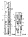
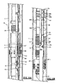
- FIG. 1A and 1B there is shown in position within a longitudinally extending well W a first perforated well conduit section C extending from the top of the well (not shown) through a production zone PZ with a longitudinally extending section of circumferentially implaced perforations P shot therethrough for communication to production within the production zone PZ.
- the perforations P are, for purposes of the present method, provided in an uppermost portion of perforations UP and a lowermost portion of perforations LP, the line between each of the portions of the perforations UP, LP, being, of course, indefinite, and being determined by the amount of treatment and positions of the apparatus for treatment for removal of the lost circulation material, as hereinafter provided.
- the perforating equipment (not shown) is withdrawn from the well.
- the perforating equipment may either be wireline, or conveyed into the well on tubing, the particular method of perforating the well not being a part of the present invention.
- the perforations Prior to withdrawal of the perforating equipment, the perforations are temporarily plugged by means of circulation into the well of a lost circulation material, such as fluid containing carboxymethylcellulose, or the like, and such material LCM is temporarily implaced within the perforations to block fluid communication there across.
- a second conduit 10 which may be a tubular work string, production tubing, or a wireline is introduced within the interior of the well W and the well conduit section C, concentrically.
- the second conduit 10 carries at its lowermost end a zone isolator 11, tail pipe section 11a therebelow and fluid communicating means 12 with fluid communicating member 12a and 12b.
- the fluid communicating means 12 will include the two screens 12a and 12b and the upper screen 12a will be in proximity to the uppermost end of the perforations P by being positioned across the upper position UP of the perforations P.
- the fluid communicating means will then include as the second communicating member the lower screen 12b and another flow passage or port such as cross-over port 18c and its interrelated fluid flow passages, as the first fluid communicating member.
- the port 18c will be positioned in proximity to the uppermost end of the perforations by actually being placed somewhat above such perforations P, as shown in Figs. 1A, 1B.
- a sump latching and securing device 13 which is stabbed through the hollow interior SP-1 of a sump packer mechanism SP which serves to locate the bottom of the well W below the production zone PZ.
- the lowermost end of the tail pipe 11a is stabbed through the interior SP-1 of the sump packer SP such that the sump latching and securing device 13 collet mechanism will flex outwardly upon passage through the lowermost end of the sump packer SP to prevent the tool from passing upwardly until the latching mechanism is activated, in a known manner, to permit retrieval of the tail pipe section 11a and zone isolator 11 from the position as shown in Figs. 1A and 1B.
- the zone isolator 11, tail pipe section 11a, fluid communication means 12, together with the securing device 13, may be run into the well on the second conduit 10 which may be either an electric line or wireline. If the conduit 10 is such an electric or wireline, the zone isolator 11 will be set using such line in a known fashion, and the line will be retrieved to the top of the well. Thereafter, a work string or production string will be run into the well and secured in a known manner to the zone isolator 11.
- the zone isolator 11, or well packer may be one of a number of commercially available devices, its purposes being to sealingly isolate the production zone PZ from the interior of the well thereabove, it being sufficient that is provide a sealing means, such as a section of an elastomeric material 27 and means, such as slips 26, for gripping and securing the isolator 11 in position against longitudinal and/or rotational movement within the well above the zone PZ.
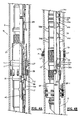
- Such packer is hydraulically activated to the set position (Fig. 3A) by means of a ball 20 (Fig. 2B) which is pumped or gravitated to a seating position on a setting sleeve 19 which is shearably secured to an inner mandrel member 36 longitudinally positioned within the tail pipe section 11a.
- fluid pressure is increased within the conduit 10 such that fluid may enter a piston chamber 30 through a port 31 in the setting mechanism portion of the zone isolator 11 to act upon a piston setting sleeve 29 to actuate the slips 26 outwardly and into gripping engagement with the well conduit C and move the packing mechanism seal 27 for sealing securement along the interior wall of the well conduit section C.
- hydraulic pressure is increased over the amount which is predeterminedly calculated and required to set the isolator 11 such that the ball seat 19 is shearingly disengaged within the interior of the inner mandrel 36 and it drops, together with the ball 20, to the lowermost end of the inner mandrel 36, as shown in Fig. 3B.
- the tail pipe section 11a has an inwardly extending indicator means 25 having an internal diameter less than the interior diameter of the tail pipe section 11a with an upwardly facing indicating surface 25b and a lower facing indicator surface 25a thereon.
- the inner mandrel 36 has a series of longitudinally spaced outwardly beveled flexible indicating means, 14a, 14b and 14c which, when they contact the respective faces 25a, 25b of the locating means 25 cause resistance to longitudinal movement of the conduit 10, thereby indicating at the top of the well that the mandrel 36 is at a predetermined and known position within the tail pipe section 11a for performing various operations in which a desired flow path is selected according to the position of the inner mandrel 36 relative to the tail pipe section 11a and isolator 11.
- the uppermost indicator 14c is positioned on the upper face 25b of the locator means 25 thereby indicating to the operator at the top of the well that the apparatus is in the position for initial treatment of the lowermost perforations LP, and is also in the position shown in Fig. 7B, during treatment of the well for removal of the lost circulation material, or during the gravel packing operation (Fig. 10B).
- the conduit 10 is manipulated such that the tail pipe 11a is moved upwardly from, for example, the position shown in Fig. 7B, to the position shown in Fig.
- the middle indicator 14b will contact the uppermost locating face 25b of the locating means 25 to indicate to the operator that the apparatus is in the position shown in, for example Fig. 8B.
- the flow path through the apparatus and the well would then be as shown by the arrows in Figs. 8A and 8B.
- the apparatus When the apparatus is moved to its uppermost position by means of manipulation of the conduit 10 to move the tail pipe section 11a such that the lowermost indicator 14a may be positioned on the upper face 25b of a locator means 25, the apparatus is in the position shown in Fig. 9B to prevent circulation of fluid interiorly through the isolator 11, but through the annular area above the isolator 11 and into the interior of the conduit 10 for washing out of the interior of the well W above the isolator 11.
- the flow path for fluid would be as shown in Figs. 9A and 9B with the apparatus in this position.
- the tail pipe section 11a will move correspondingly within the well W and the indicators 14a, 14b and 14c will contact and pass the lower face 25a of the locating means 25, indicating to the operator that only slight continued pickup of the tubing conduit 10 is necessary and that light set down may be implaced until the selected indicator, 14a, 14b, or 14c contacts the upper face 25b of the locating means 25 to resist further downward movement of the conduit 10 to indicate to the operator that the selected positioning of the tail pipe 11a and the apparatus are at the desired position within the well for the selected operation.
- the inner mandrel 36 also has an outwardly extending locating mechanism 24 placed circumferentially around the exterior of the mandrel 36 and somewhat below the lowermost indicator means 14a for contact with a companion upwardly facing shoulder 23a of a seal bore receptacle 23.
- the inner mandrel 36 Upon engagement of the shoulders 24, 23a the inner mandrel 36 will be prevented from further downward longitudinal movement within the tail pipe section 11a, and the operator will know that the inner mandrel 36 is in position whereby a set of chevron or other configured sealed member 36a placed circumferentially around the exterior of the inner mandrel 36 below the member 24 will be within a receptacle for sealing securement within the interior of the seal receptacle 23, thereby isolating the first and second fluid communication members 12a and 12b relative to the interior of the inner mandrel 36.
- the inner mandrel 36 has below the seal section 36a a series of ports 22 positioned just above its lowermost sealed end 36b. It is through these ports 22 that fluid will flow in a manner hereinafter described. It should be noted that the ports 22 are positioned slightly above the position of the isolator 11 setting ball and seat 20, 19 when same are shearingly removed from the interior of the inner mandrel 36 after the setting of the isolator 11, as described above.
- a series of centralizers 36b are selectively longitudinally positioned around the exterior or the tail pipe section 11a.
- a cross-over tool assembly includes the inner mandrel 36 having a long longitudinally extending set of seals 36a for sealing within the interior of the isolator 11 as the conduit 10 is manipulated to position for providing the various fluid flow paths as hereinafter described.
- the cross-over tool is defined by concentrically disposed tubing members T-1 and T-2 which extend downwardly out of the interior of the isolator 11 and within the uppermost end of the tail pipe section 11a.
- a seal seat 18 is provided thereon for receipt of a ball member 18b (Fig.
- the conduit 10 is manipulated after the isolator 11 is hydraulically set. Such manipulation preferably is in the form of rotational movement in a first direction to permit a floating securing nut 28 to become unthreaded relative to the housing of the isolator 11. Once the threads relative to the nut 28 and housing of the isolator 11 are broken, the conduit 10 may be picked up to separate a setting sleeve 29 and permit fluid flow into the annulus between the second conduit 10 and the well conduit C above the isolator 11, as shown in, for example, Fig. 7A.
- fluid may flow upward and out of the uppermost end of the cross-over tool through at annular area between the concentric members T-1, T-2 of the cross-over tool at opening 33, thence in the annular area 34 above the isolator 11 defined between the interior of the conduit C and the exterior of the conduit 10 for return to the top of the well.
- a flapper valve mechanism 40 is shown in open posittion (Fig. 7A).
- the flapper mechanism 40 is spring biased closed, but is urged open by upward flow of fluid, as shown by the arrows in Fig. 7A.
- the isolator 11 When the apparatus is positioned within the well W as shown in Figs. 1A, 1B, the isolator 11 is above the production zone PZ and the fluid communicating means 12 has its uppermost member 12a in proximity to uppermost end of the perforations P, with the lowermost fluid communicating means 12b positioned somewhat below and in proximity to the lowermost portions LP of the perforations P.
- the seals 36a on the exterior of the inner mandrel 36 are sealingly received within the seal receptacle 23.
- the ball 20 for the setting of the hydraulic isolator 11 is gravitated or pumped down the interior of the conduit 10 and is sealingly positioned upon the ball seat or sleeve 19. Fluid pressure within the interior of the conduit 10 is increased and passes through the port 31 into the piston chamber 30 to urge the setting sleeve 29 down relative to the seal mechanism 27 and slip assembly 26 to secure the slips into gripping engagement along the interior of the conduit C, as shown in Fig. 3A.
- the cross-over tool and conduit 10 are disengaged from the interior of the packing element 11 by rotationally manipulating the conduit 10 to free the nut 28 from threaded engagement within the interior of the uppermost portion of the isolator 11.
- the conduit 10 is picked up until the uppermost indicator 14c passes above the indicator means 25.
- set down weight is applied, slightly, until the lowermost face of the upper indicator 14c rests upon the upper face 25b of the locator 25 and the operator at the top of the well thus receives an indication of weight resistance relative to movement of the conduit 10, thus indicating that the apparatus is in the position shown in Figs.
- a valve at the top of the well may close the tubing casing annulus defined between the interior of the perforated well conduit section C and the exterior of the concentrically disposed second conduit 10 may be manipulated to closed position, thus preventing fluid returns to the top of the well through this annular area above the zone isolator 11.
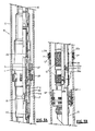
- the fluid containing lost circulation removal chemical such as a solution of 5% active hydrochloric acid or an unsaturated viscous brine, or the like, may continue to be introduced through the interior of the conduit 10 for passage through the inner mandrel 36 and outwardly thereof through the ports 22, then from the interior of the tail pipe 11a to the exterior thereof through the lowermost fluid communicating means 12b.
- the volume of this annular area and the interior of the conduit 10 and inner mandrel 36 will be known, as well as the positions of the lowermost perforations LP relative to the uppermost end of the sump packer SP. Accordingly, the amount of fluid which is required to treat only the lowermost portions of the perforations LP may be calculated and such introduced through the conduit 10. With the annular valve at the top of the well in the closed position, such fluid may be "squeezed” upon increase of pressure into such lowermost portions of the perforations LP for removal of the lost circulation material LCM, as shown in Figs. 4A-4B. Pressure may be increased within the conduit 10 to "squeeze" the fluid containing the lost circulation material removal fluid into the lower perforations LP, as shown in either Figs.
- the port 33 is sealingly positioned within the interior of the isolator 11 to prevent fluid communication through the interior of the isolator 11 and the annular area thereabove to the top of the well.
- the annular valve at the top of the well may be left open, and the conduit 10 with the cross-over means and inner mandrel 36 positioned with the indicator 24 placed upon the uppermost face 23a of the seal bore receptacle 23.
- a cross-over tool port opening ball 18b is placed within the interior of the conduit 10 and permitted to sealingly rest upon a companion uppermost facing seat 18 which is shearably secured to the interior of the innermost concentric member of the cross-over assembly.
- a companion uppermost facing seat 18 which is shearably secured to the interior of the innermost concentric member of the cross-over assembly.
- fluid will not be permitted to pass interiorly through the inner mandrel 36 below the ball 18b and its seat 18, but such fluid will be permitted to pass inwardly through the conduit 10, outwardly of the cross-over means by means of the port 18c, thence through a port 17 within the tail pipe assembly 11a to the annular area defined below the isolator 11 by the interior of the well perforated conduit section C and the exterior of the tail pipe assembly 11a.
- the fluid will now pass downwardly until it comes into contact with that section of the perforations above the lowermost portion LP of the perforations P and identified as the uppermost portion of the perforations UP which have not been previously treated by means of the squeezing of the fluid as shown in, for example, the position of the tool in Figs. 5A-5B.
- the lost circulation removal fluid will contact and enter into and throughout the various perforations and will remove such lost circulation material LCM as it is either removal through such upper perforations UP, or drops within the zone for passage through the lowermost perforations LP.
- the fluid flow will pass below the perforations LP, into the lowermost fluid communicating means 12b, thence within the interior of the inner mandrel 36 through the ports 22 and upwardly interior of the inner mandrel 36 thence through the cross-over tool and between the concentric members T-1, T-2, thereof until it passes through the upper end 33 of the concentrically disposed cross-over tool members and into the annulus 34 above the isolator 11, thence into the annular area 34 to the top of the well.
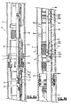
- the fluid can be "squeezed" into the upper perforations UP and lower perforations LP by having the tool in the position as shown in Figs. 7A and 7B and by closing the valve at the top of the well controlling the tubing-casing annulus.
- the main purpose of establishing the flow path as shown in Figs. 7A-7B from the position shown in Figs. 4A-4B or 5A-5B, is to permit the fluid to pass in the direction shown by the arrows in Figs. 8A-8B, to wash out the lost circulation material after the lost circulation material removing fluid has been squeezed or injected into the perforations by means of the position of the tool.
- the washing position is as shown in Figs. 7A-7B.
- the apparatus is moved to the position shown in Figs. 8A-8B and the uppermost portion of the perforations UP are treated with the fluid for removal of the lost circulation material LCM.
- the inner mandrel 36 has been moved upwardly such that the seal 36a are not sealing engaged within the receptacle 23.
- the tool After completion of the removal of the lost circulation material LCM from the uppermost portions UP of the perforations P by positioning the tool as shown in Figs. 8A-8B, the tool is moved to the position shown in Figs. 9A-9B by picking up completely on the conduit 10 to raise same until the port 18c is above the uppermost end of the isolator 11. Seals 36b are still positioned within the interior of the isolator 11, thus preventing fluid from passing inwardly of the interior 11 and to the well below the isolator 11. The purpose of positioning the tool as shown in Figs. 9A-9B in such position is to wash out the annular area of the tool above the isolator 11 to remove any of the fluid which has contained the lost circulation removal fluid.
- the tool may be repositioned to the position shown in Figs. 10A-10B (which is also the same position of the tool as shown in Figs. 7A-7B) where a gravel packing fluid and gravel are placed into the uppermost end of the conduit 10 at the top of the well and pumped through the conduit 10 for passage out of the port 18c in the cross-over tool and through the port 17 in the tail pipe section 11a, such that gravel may be deposited above the sump packer SP in the annular area defined by the interior of the casing C and the exterior of the tail pipe section 11a until the lower fluid communicating means 12b is covered with gravel.
- a gravel packing fluid and gravel are placed into the uppermost end of the conduit 10 at the top of the well and pumped through the conduit 10 for passage out of the port 18c in the cross-over tool and through the port 17 in the tail pipe section 11a, such that gravel may be deposited above the sump packer SP in the annular area defined by the interior of the casing C and the exterior of the tail pipe section 11a until the lower fluid
- the conduit 10 may be picked up and moved to position to remove the seal 36a out of the seal receptacle 23 to the position shown in Figs. 11A-11B (which is also the position shown in Figs. 8A-8B).
- the gravel packing fluid may be continued to be pumped to cover the exterior of the fluid communicating means member 12a and the fluid passing to the top of the well in the same fluid flow path as described in Figs. 10A-10B and as shown in Figs. 11A-11B.
- the tool may then be shifted to the position shown in Figs. 9A-9B for cleaning out of the annular are above the well isolator 11.
- the conduit 10 with the inner mandrel 36 carried thereon may be completely removed from the well, the well killed, and production tubing run into an stabbed into the uppermost end of the isolator 11 for subsequent production of the well through the fluid communicating means 12 and the interior of the tail pipe 11a.
- the fluid communicating members 12a and 12b may take a variety of forms. They may be provided in the form of ported or slotted tubing members, or may be wire wrapped screen having circumferentially extending open slots therethrough, or any other readily available forms known to those skilled in the art.
- hydraulically actuated packer While a hydraulically actuated packer is preferably utilized, it will be appreciated that mechanically actuated packers may also be utilized to perform the method of this invention. Such packers may be set and/or retrieved by mechanical action including a number of variations of tubing reciprocation, or incorporation of electrical impulse energized formats for a portion or all of the setting and/or retrieval modes.
- the fluid used to remove the material preferably is injected into the perforations until a loss of circulation is indicated by means of a substantial drop control pressure within the conduit 10. This loss of pressure will indicate that the material LCM has been effectively driven out of the lower perforations LP to the extent that the zone is taken fluid.
- the upper perforations UP containing the lost circulation material LCM may be subjected to the fluid until the material LCM is removed therefrom, as further indicated by substantial pressure drop within the conduit 10 during this second treatment step.
Landscapes
- Geology (AREA)
- Life Sciences & Earth Sciences (AREA)
- Engineering & Computer Science (AREA)
- Mining & Mineral Resources (AREA)
- Environmental & Geological Engineering (AREA)
- Fluid Mechanics (AREA)
- Physics & Mathematics (AREA)
- General Life Sciences & Earth Sciences (AREA)
- Geochemistry & Mineralogy (AREA)
- Pipe Accessories (AREA)
- Physical Or Chemical Processes And Apparatus (AREA)
- Extraction Or Liquid Replacement (AREA)
- Feeding, Discharge, Calcimining, Fusing, And Gas-Generation Devices (AREA)
Applications Claiming Priority (2)
| Application Number | Priority Date | Filing Date | Title |
|---|---|---|---|
| US417657 | 1989-10-05 | ||
| US07/417,657 US4951750A (en) | 1989-10-05 | 1989-10-05 | Method and apparatus for single trip injection of fluid for well treatment and for gravel packing thereafter |
Publications (3)
| Publication Number | Publication Date |
|---|---|
| EP0421822A2 true EP0421822A2 (fr) | 1991-04-10 |
| EP0421822A3 EP0421822A3 (en) | 1991-10-23 |
| EP0421822B1 EP0421822B1 (fr) | 1996-05-08 |
Family
ID=23654886
Family Applications (1)
| Application Number | Title | Priority Date | Filing Date |
|---|---|---|---|
| EP90310978A Expired - Lifetime EP0421822B1 (fr) | 1989-10-05 | 1990-10-05 | Procédé et dispositif pour l'injection d'un fluide de traitement de puits et pour la mise en place d'un filtre à gravier en une seule manoeuvre |
Country Status (4)
| Country | Link |
|---|---|
| US (1) | US4951750A (fr) |
| EP (1) | EP0421822B1 (fr) |
| AT (1) | ATE137838T1 (fr) |
| DE (1) | DE69026895D1 (fr) |
Cited By (5)
| Publication number | Priority date | Publication date | Assignee | Title |
|---|---|---|---|---|
| EP1132571A1 (fr) * | 2000-03-07 | 2001-09-12 | Halliburton Energy Services, Inc. | Procédé et appareil pour la fracturation et installation de filtre à gravier |
| US6427775B1 (en) | 1997-10-16 | 2002-08-06 | Halliburton Energy Services, Inc. | Methods and apparatus for completing wells in unconsolidated subterranean zones |
| US6557635B2 (en) | 1997-10-16 | 2003-05-06 | Halliburton Energy Services, Inc. | Methods for completing wells in unconsolidated subterranean zones |
| US6776236B1 (en) | 2002-10-16 | 2004-08-17 | Halliburton Energy Services, Inc. | Methods of completing wells in unconsolidated formations |
| WO2022169588A1 (fr) * | 2021-02-05 | 2022-08-11 | Schlumberger Technology Corporation | Système et procédé de stimulation de multiples zones |
Families Citing this family (17)
| Publication number | Priority date | Publication date | Assignee | Title |
|---|---|---|---|---|
| US5174379A (en) * | 1991-02-11 | 1992-12-29 | Otis Engineering Corporation | Gravel packing and perforating a well in a single trip |
| FR2676664B1 (fr) * | 1991-05-22 | 1995-01-27 | Vaillant Materiels Vincent | Dispositif autorisant le controle et l'action d'effets vibratoires sur des machines destinees notamment a la fabrication de produits destines a etre vibres et compactes. |
| US5332038A (en) * | 1992-08-06 | 1994-07-26 | Baker Hughes Incorporated | Gravel packing system |
| US5343949A (en) * | 1992-09-10 | 1994-09-06 | Halliburton Company | Isolation washpipe for earth well completions and method for use in gravel packing a well |
| US5360069A (en) * | 1993-03-30 | 1994-11-01 | Baker Hughes Incorporated | Failsafe liner installation assembly and method |
| US5341880A (en) * | 1993-07-16 | 1994-08-30 | Halliburton Company | Sand screen structure with quick connection section joints therein |
| US5595246A (en) * | 1995-02-14 | 1997-01-21 | Baker Hughes Incorporated | One trip cement and gravel pack system |
| US6241013B1 (en) * | 1998-08-25 | 2001-06-05 | Halliburton Energy Services, Inc. | One-trip squeeze pack system and method of use |
| US6176307B1 (en) * | 1999-02-08 | 2001-01-23 | Union Oil Company Of California | Tubing-conveyed gravel packing tool and method |
| US6286598B1 (en) * | 1999-09-29 | 2001-09-11 | Halliburton Energy Services, Inc. | Single trip perforating and fracturing/gravel packing |
| US7021389B2 (en) * | 2003-02-24 | 2006-04-04 | Bj Services Company | Bi-directional ball seat system and method |
| US7311153B2 (en) * | 2004-06-18 | 2007-12-25 | Schlumberger Technology Corporation | Flow-biased sequencing valve |
| US7565835B2 (en) * | 2004-11-17 | 2009-07-28 | Schlumberger Technology Corporation | Method and apparatus for balanced pressure sampling |
| US7845399B2 (en) * | 2008-10-28 | 2010-12-07 | Morley Sebree | Downhole well pump |
| US9115549B2 (en) | 2012-06-28 | 2015-08-25 | Team Oil Tools, L.P. | Method and apparatus for injecting gas into a reservoir |
| US9388661B2 (en) * | 2012-07-31 | 2016-07-12 | Schlumberger Technology Corporation | Methods and systems for treating a wellbore |
| US9528339B2 (en) * | 2013-12-05 | 2016-12-27 | Jeffrey J. Brown | Downhole fishing tool and method of use |
Family Cites Families (14)
| Publication number | Priority date | Publication date | Assignee | Title |
|---|---|---|---|---|
| US3710862A (en) * | 1971-06-07 | 1973-01-16 | Otis Eng Corp | Method and apparatus for treating and preparing wells for production |
| US3818986A (en) * | 1971-11-01 | 1974-06-25 | Dresser Ind | Selective well treating and gravel packing apparatus |
| US3913675A (en) * | 1974-10-21 | 1975-10-21 | Dresser Ind | Methods and apparatus for sand control in underground boreholes |
| US3963076A (en) * | 1975-03-07 | 1976-06-15 | Baker Oil Tools, Inc. | Method and apparatus for gravel packing well bores |
| US4027732A (en) * | 1975-08-06 | 1977-06-07 | Kajan Specialty Company, Inc. | Tool for washing perforations in cased well bore |
| US4279306A (en) * | 1979-08-10 | 1981-07-21 | Top Tool Company, Inc. | Well washing tool and method |
| US4431058A (en) * | 1981-03-16 | 1984-02-14 | Baker International Corporation | Wash tool method for subterranean wells |
| US4541486A (en) * | 1981-04-03 | 1985-09-17 | Baker Oil Tools, Inc. | One trip perforating and gravel pack system |
| US4484625A (en) * | 1982-04-20 | 1984-11-27 | The Western Company Of North America | Well casing perforated zone washing apparatus |
| US4519451A (en) * | 1983-05-09 | 1985-05-28 | Otis Engineering Corporation | Well treating equipment and methods |
| US4570714A (en) * | 1983-12-22 | 1986-02-18 | Geo Vann, Inc. | Gravel pack assembly |
| US4566538A (en) * | 1984-03-26 | 1986-01-28 | Baker Oil Tools, Inc. | Fail-safe one trip perforating and gravel pack system |
| US4733723A (en) * | 1986-07-18 | 1988-03-29 | Callegari Sr Stephen R | Gravel pack assembly |
| US4815538A (en) * | 1988-06-16 | 1989-03-28 | The Cavins Corporation | Wash tool for well having perforated casing |
-
1989
- 1989-10-05 US US07/417,657 patent/US4951750A/en not_active Expired - Fee Related
-
1990
- 1990-10-05 AT AT90310978T patent/ATE137838T1/de not_active IP Right Cessation
- 1990-10-05 DE DE69026895T patent/DE69026895D1/de not_active Expired - Lifetime
- 1990-10-05 EP EP90310978A patent/EP0421822B1/fr not_active Expired - Lifetime
Cited By (10)
| Publication number | Priority date | Publication date | Assignee | Title |
|---|---|---|---|---|
| US6427775B1 (en) | 1997-10-16 | 2002-08-06 | Halliburton Energy Services, Inc. | Methods and apparatus for completing wells in unconsolidated subterranean zones |
| US6481494B1 (en) | 1997-10-16 | 2002-11-19 | Halliburton Energy Services, Inc. | Method and apparatus for frac/gravel packs |
| US6540022B2 (en) | 1997-10-16 | 2003-04-01 | Halliburton Energy Services, Inc. | Method and apparatus for frac/gravel packs |
| US6557635B2 (en) | 1997-10-16 | 2003-05-06 | Halliburton Energy Services, Inc. | Methods for completing wells in unconsolidated subterranean zones |
| US6571872B2 (en) | 1997-10-16 | 2003-06-03 | Halliburton Energy Services, Inc. | Apparatus for completing wells in unconsolidated subterranean zones |
| US6755245B2 (en) | 1997-10-16 | 2004-06-29 | Halliburton Energy Services, Inc. | Apparatus for completing wells in unconsolidated subterranean zones |
| EP1132571A1 (fr) * | 2000-03-07 | 2001-09-12 | Halliburton Energy Services, Inc. | Procédé et appareil pour la fracturation et installation de filtre à gravier |
| US6776236B1 (en) | 2002-10-16 | 2004-08-17 | Halliburton Energy Services, Inc. | Methods of completing wells in unconsolidated formations |
| WO2022169588A1 (fr) * | 2021-02-05 | 2022-08-11 | Schlumberger Technology Corporation | Système et procédé de stimulation de multiples zones |
| US12123290B2 (en) | 2021-02-05 | 2024-10-22 | Schlumberger Technology Corporation | System and method for stimulating multiple zones |
Also Published As
| Publication number | Publication date |
|---|---|
| ATE137838T1 (de) | 1996-05-15 |
| EP0421822A3 (en) | 1991-10-23 |
| US4951750A (en) | 1990-08-28 |
| EP0421822B1 (fr) | 1996-05-08 |
| DE69026895D1 (de) | 1996-06-13 |
Similar Documents
| Publication | Publication Date | Title |
|---|---|---|
| US4951750A (en) | Method and apparatus for single trip injection of fluid for well treatment and for gravel packing thereafter | |
| EP0796980B1 (fr) | Méthode et dispositif pour isoler des zones | |
| US7096945B2 (en) | Sand control screen assembly and treatment method using the same | |
| US4401158A (en) | One trip multi-zone gravel packing apparatus | |
| US6886634B2 (en) | Sand control screen assembly having an internal isolation member and treatment method using the same | |
| US6719051B2 (en) | Sand control screen assembly and treatment method using the same | |
| US6899176B2 (en) | Sand control screen assembly and treatment method using the same | |
| US6176307B1 (en) | Tubing-conveyed gravel packing tool and method | |
| US6725929B2 (en) | Circulation tool for use in gravel packing of wellbores | |
| US4372384A (en) | Well completion method and apparatus | |
| US6772837B2 (en) | Screen assembly having diverter members and method for progressively treating an interval of a welibore | |
| CA2416040C (fr) | Procede pour traiter les intervalles multiples dans un trou de forage | |
| US6776238B2 (en) | Single trip method for selectively fracture packing multiple formations traversed by a wellbore | |
| US7191833B2 (en) | Sand control screen assembly having fluid loss control capability and method for use of same | |
| US4771829A (en) | Well liner with selective isolation screen | |
| US6230803B1 (en) | Apparatus and method for treating and gravel-packing closely spaced zones | |
| US6241013B1 (en) | One-trip squeeze pack system and method of use | |
| AU2004203024B2 (en) | Method and apparatus for treating a well | |
| US20040003922A1 (en) | Method for selectively treating two producing intervals in a single trip | |
| US4510999A (en) | Well cleanup and completion method and apparatus | |
| WO2001049970A1 (fr) | Dispositif et procede de traitement et de gravillonnage de zones etroitement espacees | |
| EP0823538A2 (fr) | Procédé pour la stimulation d'un puits souterrain | |
| AU2022252168B2 (en) | Open hole multi-zone single trip completion system | |
| GB2358033A (en) | A perforation apparatus |
Legal Events
| Date | Code | Title | Description |
|---|---|---|---|
| PUAI | Public reference made under article 153(3) epc to a published international application that has entered the european phase |
Free format text: ORIGINAL CODE: 0009012 |
|
| AK | Designated contracting states |
Kind code of ref document: A2 Designated state(s): AT BE CH DE DK ES FR GB GR IT LI LU NL SE |
|
| PUAL | Search report despatched |
Free format text: ORIGINAL CODE: 0009013 |
|
| AK | Designated contracting states |
Kind code of ref document: A3 Designated state(s): AT BE CH DE DK ES FR GB GR IT LI LU NL SE |
|
| 17P | Request for examination filed |
Effective date: 19920414 |
|
| 17Q | First examination report despatched |
Effective date: 19940414 |
|
| GRAH | Despatch of communication of intention to grant a patent |
Free format text: ORIGINAL CODE: EPIDOS IGRA |
|
| GRAA | (expected) grant |
Free format text: ORIGINAL CODE: 0009210 |
|
| AK | Designated contracting states |
Kind code of ref document: B1 Designated state(s): AT BE CH DE DK ES FR GB GR IT LI LU NL SE |
|
| PG25 | Lapsed in a contracting state [announced via postgrant information from national office to epo] |
Ref country code: IT Free format text: LAPSE BECAUSE OF FAILURE TO SUBMIT A TRANSLATION OF THE DESCRIPTION OR TO PAY THE FEE WITHIN THE PRE;WARNING: LAPSES OF ITALIAN PATENTS WITH EFFECTIVE DATE BEFORE 2007 MAY HAVE OCCURRED AT ANY TIME BEFORE 2007. THE CORRECT EFFECTIVE DATE MAY BE DIFFERENT FROM THE ONE RECORDED.SCRIBED TIME-LIMIT Effective date: 19960508 Ref country code: GR Free format text: LAPSE BECAUSE OF FAILURE TO SUBMIT A TRANSLATION OF THE DESCRIPTION OR TO PAY THE FEE WITHIN THE PRESCRIBED TIME-LIMIT Effective date: 19960508 Ref country code: NL Free format text: LAPSE BECAUSE OF FAILURE TO SUBMIT A TRANSLATION OF THE DESCRIPTION OR TO PAY THE FEE WITHIN THE PRESCRIBED TIME-LIMIT Effective date: 19960508 Ref country code: DK Effective date: 19960508 Ref country code: FR Effective date: 19960508 Ref country code: BE Effective date: 19960508 Ref country code: LI Effective date: 19960508 Ref country code: ES Free format text: THE PATENT HAS BEEN ANNULLED BY A DECISION OF A NATIONAL AUTHORITY Effective date: 19960508 Ref country code: CH Effective date: 19960508 Ref country code: AT Effective date: 19960508 |
|
| REF | Corresponds to: |
Ref document number: 137838 Country of ref document: AT Date of ref document: 19960515 Kind code of ref document: T |
|
| REF | Corresponds to: |
Ref document number: 69026895 Country of ref document: DE Date of ref document: 19960613 |
|
| PG25 | Lapsed in a contracting state [announced via postgrant information from national office to epo] |
Ref country code: SE Effective date: 19960808 |
|
| PG25 | Lapsed in a contracting state [announced via postgrant information from national office to epo] |
Ref country code: DE Effective date: 19960809 |
|
| NLV1 | Nl: lapsed or annulled due to failure to fulfill the requirements of art. 29p and 29m of the patents act | ||
| EN | Fr: translation not filed | ||
| PG25 | Lapsed in a contracting state [announced via postgrant information from national office to epo] |
Ref country code: GB Effective date: 19961005 |
|
| PG25 | Lapsed in a contracting state [announced via postgrant information from national office to epo] |
Ref country code: LU Free format text: LAPSE BECAUSE OF NON-PAYMENT OF DUE FEES Effective date: 19961031 |
|
| REG | Reference to a national code |
Ref country code: CH Ref legal event code: PL |
|
| PLBE | No opposition filed within time limit |
Free format text: ORIGINAL CODE: 0009261 |
|
| STAA | Information on the status of an ep patent application or granted ep patent |
Free format text: STATUS: NO OPPOSITION FILED WITHIN TIME LIMIT |
|
| 26N | No opposition filed | ||
| GBPC | Gb: european patent ceased through non-payment of renewal fee |
Effective date: 19961005 |