EP0421942A1 - Instrument pour le nettoyage de la surface des dents - Google Patents
Instrument pour le nettoyage de la surface des dents Download PDFInfo
- Publication number
- EP0421942A1 EP0421942A1 EP90830098A EP90830098A EP0421942A1 EP 0421942 A1 EP0421942 A1 EP 0421942A1 EP 90830098 A EP90830098 A EP 90830098A EP 90830098 A EP90830098 A EP 90830098A EP 0421942 A1 EP0421942 A1 EP 0421942A1
- Authority
- EP
- European Patent Office
- Prior art keywords
- duct
- reservoir
- powder
- spray head
- instrument
- Prior art date
- Legal status (The legal status is an assumption and is not a legal conclusion. Google has not performed a legal analysis and makes no representation as to the accuracy of the status listed.)
- Withdrawn
Links
- 238000004140 cleaning Methods 0.000 title claims description 5
- 239000000843 powder Substances 0.000 claims abstract description 34
- 239000007921 spray Substances 0.000 claims abstract description 23
- 239000011800 void material Substances 0.000 claims abstract description 10
- 239000000203 mixture Substances 0.000 claims description 16
- XLYOFNOQVPJJNP-UHFFFAOYSA-N water Substances O XLYOFNOQVPJJNP-UHFFFAOYSA-N 0.000 claims description 12
- 238000007789 sealing Methods 0.000 claims description 3
- 239000002131 composite material Substances 0.000 claims description 2
- 239000012530 fluid Substances 0.000 claims description 2
- 230000000694 effects Effects 0.000 abstract description 2
- 238000001356 surgical procedure Methods 0.000 description 4
- 238000013461 design Methods 0.000 description 3
- 238000010276 construction Methods 0.000 description 1
- 230000008878 coupling Effects 0.000 description 1
- 238000010168 coupling process Methods 0.000 description 1
- 238000005859 coupling reaction Methods 0.000 description 1
- 230000001747 exhibiting effect Effects 0.000 description 1
- 238000010348 incorporation Methods 0.000 description 1
- 238000003780 insertion Methods 0.000 description 1
- 230000037431 insertion Effects 0.000 description 1
- 238000000034 method Methods 0.000 description 1
- NJPPVKZQTLUDBO-UHFFFAOYSA-N novaluron Chemical compound C1=C(Cl)C(OC(F)(F)C(OC(F)(F)F)F)=CC=C1NC(=O)NC(=O)C1=C(F)C=CC=C1F NJPPVKZQTLUDBO-UHFFFAOYSA-N 0.000 description 1
- 238000012856 packing Methods 0.000 description 1
- 150000003839 salts Chemical class 0.000 description 1
- 238000005488 sandblasting Methods 0.000 description 1
Images

Classifications
-
- A—HUMAN NECESSITIES
- A61—MEDICAL OR VETERINARY SCIENCE; HYGIENE
- A61C—DENTISTRY; APPARATUS OR METHODS FOR ORAL OR DENTAL HYGIENE
- A61C3/00—Dental tools or instruments
- A61C3/02—Tooth drilling or cutting instruments; Instruments acting like a sandblast machine
- A61C3/025—Instruments acting like a sandblast machine, e.g. for cleaning, polishing or cutting teeth
Definitions
- the present invention relates to a dental surgery instrument for cleaning teeth.
- Conventional dental surgery equipment embraces a wide variety of instruments designed to clean the surfaces of teeth employing what is essentially a sand-blasting technique.
- such instruments will consist in a fixed (or table-top) component, and a handpiece, as disclosed in US 3 882 638, for example.
- the stationary component comprises a reservoir, containing a powder that can be entrained in air in such a way as to form a mixture high in abrasive power and thus suitable for cleaning purposes, and a swirl chamber, charged with the powder by means of compressed air and duly provided with respective openings for receipt of the compressed air and discharge of the air-and-powder mixture.
- the handpiece is the cleaning instrument proper; this comprises a fitting at one end for attachment of the powder supply line and a water supply line, and at the remaining end, a nozzle from which the air-powder mixture and water are sprayed.
- the powder supply line is relatively long, and as a result, prone to encrustation along its entire length; more exactly, the powders used in such abrasive mixtures (preferably water-soluble salts) are liable to absorb moisture during passage to the handpiece, causing not only encrustation but even complete blockage, especially at the nozzle.
- abrasive mixtures preferably water-soluble salts
- EP 182 983 discloses an improvement on the design outlined above, whereby the powder reservoir and swirl chamber are incorporated directly into the handpiece, located between the air and water supply ducts and the spray nozzle, and interconnected by way of a drilled plate which both partitions-off the swirl chamber and ensures correct distribution and metering of the powder into the chamber; also, the powder reservoir accommodates a plunger biased forward by compressed air, the purpose of which is to drive the powder toward the plate and thus take up the volume left vacant by each discharge of the contents of the reservoir into the chamber, and from the chamber through a pipe to the nozzle.
- This embodiment also betrays drawbacks from the servicing standpoint, and in addition, is unsound architecturally; with the swirl chamber located in close proximity to the nozzle, the operator has problems gaining access to the outlet pipes in the event of blockage occurring (the volume occupied by the bowl of the swirl chamber is relatively large).
- EP 163 610 discloses a handpiece with a plurality of swirl chambers positioned in series one with the next and designed to enable a thorough and uniform mixture of powder and compressed air, as well as to ensure a steady output from the nozzle regardless of the state of the reservoir and the position at which the handpiece is held.
- the same specification includes an alternative embodiment in which use is made of a replaceable powder cartridge, of which the end is pierced by air inlet and mixture outlet ducts in the handpiece at the moment of insertion.
- the patent handpiece thus described is complex in construction, in the case of the permanent chamber design, whilst the replaceable cartridge design is problematical in embodiment.
- the object of the present invention is to overcome the drawbacks described above through the adoption of an instrument that will be more economical, more easily handled, and technically more dependable.
- a handpiece as characterized in the appended claims, which is provided with a powder metering element adjacent to the spray head, comprising at least one first duct that connects on the one hand with a reservoir and emerges on the other into a corresponding second duct connecting with the mixture outlet pipe to the nozzle, thereby forming a single coaxially aligned duct extending from the reservoir to the nozzle pipe.
- the first and second ducts are of dissimilar diameter at the point where the one joins the other such that the void between them can be connected directly to the handpiece air inlet and the area beyond the emergence of the first duct evacuated, thus drawing powder out of the reservoir by suction and entraining it into the nozzle pipe.
- a significant advantage afforded by the invention is that of exploiting the compressed air supplied to the handpiece to draw powder from the reservoir and into the nozzle pipe by negative pressure, thus eliminating the problem of internal blockages, as entrainment occurs at a point close to the nozzle, and dispensing with the need to incorporate further ducts into the handpiece for the purpose of driving the plunger toward the swirl chamber pneumatically.
- the invention relates to a dental surgery instrument which cleans the external surfaces of teeth by investing them with a mixture of abrasive powder and air, sprayed together with water.
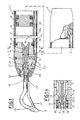
- a dental surgery instrument comprises a handpiece, denoted 1 in its entirety, of which one end carries a fitting 2 for the connection of two inlet ducts 3 and 4 (air and water respectively) to the compressed air and spray circuits of a surgery apparatus pedestal; the fitting 2 is not shown in detail, being conventional, but will be a universal type used to couple several different handpieces 1.
- the opposite end is fitted with a spray head 5 from which independent outlet pipes 26 and 27 extend forward through dissimilar routes (as discernible in fig 1) carrying the abrasive mixture and water, respectively, to a single nozzle 6.
- the reservoir 7 denotes an interchangeable reservoir accommodated internally of the handpiece 1 which, in the example illustrated, is nothing other than a simple tube of cylindrical shape, open at each end, containing the powder for the abrasive mixture and located between the fitting 2 and the spray head 5.
- the reservoir 7 is provided internally with a plunger 8, capable of movement fully end to end and in circumferential contact with the inside cylindrical wall by way of seals 33 (conventional in embodiment), in such a way as to combine with the spray head 5 in ensuring that the area containing the powder is maintained absolutely fluid-tight.
- the handpiece 1 is provided with a powder metering element 9 located next to the spray head 5, consisting substantially in a bushing 14 permanently associated via screw threads with a corresponding socket 15, positioned centrally in the spray head.
- the bushing 14 affords a first longitudinal duct 10, exhibiting a funnel shaped section 10a of which the greater diameter is directed toward the reservoir 7 and extending into a first tube 17 of which one end projects forward, beyond the metering element 9, from the part of the bushing 14 nearest the nozzle 6.
- 11 denotes a second duct afforded by the forward part of the spray head 5, communicating on the one hand with the first duct 10 and connected coaxially to the mixture outlet pipe 26 on the other, which consists in a second tube 18 emerging at one end directly into the pipe 26.
- the second tube 18 is accommodated internally of a second bushing 19 permanently inserted in a corresponding socket 20 afforded by the end section of the spray head 5.
- This same bushing 19 also exhibits a sleeve 21 at the end facing the metering element 9, and more exactly, the forward end of the element is loosely surrounded by the sleeve 21 in such a way that a void 12 is created between the two (see fig 1a).
- first duct 10 and the second duct 11 combine to create a coaxially composite duct extending from the reservoir 7 through to the pipe 26 by which the powder-air mixture is carried to the nozzle.
- the first duct 10 and the second duct 11 are of dissimilar diameter, at least where the one emerges into the other, in such a way as to combine with the sleeve 21 and the first bushing 14 in creating the void 12; the void in turn is isolated from the reservoir 7, on the one hand, by conventional type seals 16 (e.g. flexible O-rings) circumferentially encircling the first bushing 14, and from the spray head 5 on the other, by further circumferential seals 39 that encircle the second bushing 19.
- conventional type seals 16 e.g. flexible O-rings
- the void 12 is connected directly to the air inlet duct 3 which, like the water inlet duct 4, extends parallel with the reservoir 7 through the length of the handpiece 1 from the end fitting 2 to the spray head 5, at which point it is routed to the void 12 by way of the relative socket 15; the water duct 4, on the other hand, runs parallel with the air inlet duct 3 up to the head 5 (see figs 2 and 3) before continuing through the head (phantom line of fig 1) to join the relative pipe 27.
- the air inlet duct 3 which, like the water inlet duct 4, extends parallel with the reservoir 7 through the length of the handpiece 1 from the end fitting 2 to the spray head 5, at which point it is routed to the void 12 by way of the relative socket 15; the water duct 4, on the other hand, runs parallel with the air inlet duct 3 up to the head 5 (see figs 2 and 3) before continuing through the head (phantom line of fig 1) to join the relative pipe 27.
- this is embodied as a cylindrical tube with open ends; thus, the one reservoir 7 can be refilled an unlimited number of times simply by turning it through 180° to position the plunger 8 at the opposite end, and packing with fresh powder.
- Reassembly of the reservoir and handpiece involves no more than applying axial pressure to slip the open end of the tube over the spray head 5, which is fashioned with a shoulder 30 and carries O-ring type sealing means 31 to ensure the necessary fluid tight fit.
- the user can assemble the remaining component of the handpiece 1, which consists in a cylindrical sheath 1a that is slipped over the reservoir 7 firmly onto the head 5, and made fast by way of a conventional bayonet coupling; this done, it remains simply to connect the fitting 2.
- Treatment can commence at this point, and with air supplied to the handpiece 1, entering through the relative duct 3 (see arrow F1) and reaching the void 12, negative pressure will be generated at the point where the first duct 10 emerges into the second duct 11, the effect of which is to evacuate powder from the reservoir 7, propelling it through the two ducts 10 and 11 toward the outlet pipe 26; the resulting mixture of air and powder is thus flung into the pipe 26 and out to the nozzle 6, where it combines with water from the remaining pipe 27 (see arrow F2 in fig 1) to generate the spray projected ultimately from the nozzle 6.
Landscapes
- Health & Medical Sciences (AREA)
- Oral & Maxillofacial Surgery (AREA)
- Dentistry (AREA)
- Epidemiology (AREA)
- Life Sciences & Earth Sciences (AREA)
- Animal Behavior & Ethology (AREA)
- General Health & Medical Sciences (AREA)
- Public Health (AREA)
- Veterinary Medicine (AREA)
- Dental Tools And Instruments Or Auxiliary Dental Instruments (AREA)
- Dental Preparations (AREA)
- Paper (AREA)
Applications Claiming Priority (2)
| Application Number | Priority Date | Filing Date | Title |
|---|---|---|---|
| IT364689 | 1989-10-06 | ||
| IT3646A IT1235912B (it) | 1989-10-06 | 1989-10-06 | Apparecchiatura per la pulizia delle superfici dentali |
Publications (1)
| Publication Number | Publication Date |
|---|---|
| EP0421942A1 true EP0421942A1 (fr) | 1991-04-10 |
Family
ID=11111078
Family Applications (1)
| Application Number | Title | Priority Date | Filing Date |
|---|---|---|---|
| EP90830098A Withdrawn EP0421942A1 (fr) | 1989-10-06 | 1990-03-13 | Instrument pour le nettoyage de la surface des dents |
Country Status (2)
| Country | Link |
|---|---|
| EP (1) | EP0421942A1 (fr) |
| IT (1) | IT1235912B (fr) |
Cited By (1)
| Publication number | Priority date | Publication date | Assignee | Title |
|---|---|---|---|---|
| FR2712172A1 (fr) * | 1993-11-09 | 1995-05-19 | Rabier Nicolas | Dispositif de micro-abrasion cutanée en circuit ouvert. |
Citations (3)
| Publication number | Priority date | Publication date | Assignee | Title |
|---|---|---|---|---|
| EP0072487A1 (fr) * | 1981-08-14 | 1983-02-23 | Siemens Aktiengesellschaft | Appareil pour traiter, notamment nettoyer la surface de pièces, plus particulièrement des dents |
| WO1985002107A1 (fr) * | 1983-11-11 | 1985-05-23 | Sven Karl Lennart Goof | Instrument de nettoyage des dents |
| EP0248638A2 (fr) * | 1986-06-03 | 1987-12-09 | Moshe Meller | Instrument de nettoyage utilisant un liquide abrasif préparé, une méthode de nettoyage et un liquide de nettoyage abrasif |
-
1989
- 1989-10-06 IT IT3646A patent/IT1235912B/it active IP Right Grant
-
1990
- 1990-03-13 EP EP90830098A patent/EP0421942A1/fr not_active Withdrawn
Patent Citations (3)
| Publication number | Priority date | Publication date | Assignee | Title |
|---|---|---|---|---|
| EP0072487A1 (fr) * | 1981-08-14 | 1983-02-23 | Siemens Aktiengesellschaft | Appareil pour traiter, notamment nettoyer la surface de pièces, plus particulièrement des dents |
| WO1985002107A1 (fr) * | 1983-11-11 | 1985-05-23 | Sven Karl Lennart Goof | Instrument de nettoyage des dents |
| EP0248638A2 (fr) * | 1986-06-03 | 1987-12-09 | Moshe Meller | Instrument de nettoyage utilisant un liquide abrasif préparé, une méthode de nettoyage et un liquide de nettoyage abrasif |
Cited By (1)
| Publication number | Priority date | Publication date | Assignee | Title |
|---|---|---|---|---|
| FR2712172A1 (fr) * | 1993-11-09 | 1995-05-19 | Rabier Nicolas | Dispositif de micro-abrasion cutanée en circuit ouvert. |
Also Published As
| Publication number | Publication date |
|---|---|
| IT1235912B (it) | 1992-12-02 |
| IT8903646A0 (it) | 1989-10-06 |
| IT8903646A1 (it) | 1991-04-06 |
Similar Documents
| Publication | Publication Date | Title |
|---|---|---|
| US4340365A (en) | Spraying and suction cleansing device | |
| US4978297A (en) | Handpiece with additive chamber | |
| US6149509A (en) | Removable nozzle for a sandblaster handpiece | |
| US4984984A (en) | Dental tool and nozzle therefor | |
| US4648840A (en) | Dental polisher combining pressurized fluid and abrasive flow | |
| US4462803A (en) | Device for cleaning teeth | |
| US4540365A (en) | Dental cleansing system | |
| US4007529A (en) | Motor-driven dental handpiece | |
| US3120705A (en) | High-speed angle-handpieces for dental purposes | |
| US9119690B2 (en) | Fluid-operated medical or dental handheld element | |
| US5897317A (en) | Dental handpiece with disposable filter cartridge | |
| DE59712107D1 (de) | Medizinisches oder dentales Handinstrument | |
| US6293856B1 (en) | Disposable, multi-conduit particulate matter propelling apparatus | |
| EP1047527B1 (fr) | Dispositif de projection de matiere particulaire | |
| US6485303B1 (en) | Intraoral dental abrading instrument | |
| US4892112A (en) | Hand tool for cleaning disinfecting and/or lubricating | |
| KR100580900B1 (ko) | 다수의 진공 발생 유니트 | |
| JPS5940018B2 (ja) | 歯科用空気圧モ−タ装置 | |
| US5941702A (en) | Air-abrading tool | |
| US20040076922A1 (en) | Functional handpiece having a light emission element at its forward end | |
| US6287180B1 (en) | Handheld apparatus for propelling particulate matter against a surface of a patient's tooth, and method | |
| EP0421942A1 (fr) | Instrument pour le nettoyage de la surface des dents | |
| WO2008115129A1 (fr) | Dispositif de polissage dentaire | |
| EP1354565A1 (fr) | Pièce à main pour nettoyer les surfaces dentaires | |
| EP0015672A1 (fr) | Dispositif vibratoire, porte-outil et appareil dentaire de nettoyage en étant équipé |
Legal Events
| Date | Code | Title | Description |
|---|---|---|---|
| PUAI | Public reference made under article 153(3) epc to a published international application that has entered the european phase |
Free format text: ORIGINAL CODE: 0009012 |
|
| 17P | Request for examination filed |
Effective date: 19910129 |
|
| AK | Designated contracting states |
Kind code of ref document: A1 Designated state(s): CH DE ES FR GB GR LI SE |
|
| 17Q | First examination report despatched |
Effective date: 19920701 |
|
| STAA | Information on the status of an ep patent application or granted ep patent |
Free format text: STATUS: THE APPLICATION HAS BEEN WITHDRAWN |
|
| 18W | Application withdrawn |
Withdrawal date: 19930730 |