EP0421943B1 - Verfahren und Vorrichtung zum automatischen Einziehen von Kettfäden - Google Patents
Verfahren und Vorrichtung zum automatischen Einziehen von Kettfäden Download PDFInfo
- Publication number
- EP0421943B1 EP0421943B1 EP90830374A EP90830374A EP0421943B1 EP 0421943 B1 EP0421943 B1 EP 0421943B1 EP 90830374 A EP90830374 A EP 90830374A EP 90830374 A EP90830374 A EP 90830374A EP 0421943 B1 EP0421943 B1 EP 0421943B1
- Authority
- EP
- European Patent Office
- Prior art keywords
- wire
- comb
- harnesses
- fact
- return
- Prior art date
- Legal status (The legal status is an assumption and is not a legal conclusion. Google has not performed a legal analysis and makes no representation as to the accuracy of the status listed.)
- Expired - Lifetime
Links
Images




Classifications
-
- D—TEXTILES; PAPER
- D03—WEAVING
- D03J—AUXILIARY WEAVING APPARATUS; WEAVERS' TOOLS; SHUTTLES
- D03J1/00—Auxiliary apparatus combined with or associated with looms
- D03J1/14—Apparatus for threading warp stop-motion droppers, healds, or reeds
Definitions
- the present invention relates to a method for the automatic retraction of warp threads and to a machine for implementing said method.
- US Pat. No. 3,867,745 describes a process for re-entering threads of reduced length through the weaving elements of a loom, in a predetermined sequence, leaving the end of each thread for knotting the thread on the of the chain.
- US Pat. No. 3,787,938 describes a device for tucking in threads of reduced length through the weaving elements of a loom, in a predetermined sequence, leaving the end of each thread for the knotting the thread on the warp beam.
- the object of the present invention is to propose an automatic method of retracting the warp yarns for flat, open healds and a machine for implementing said method which is autonomous in its operation and therefore of reduced cost.
- said pieces of wire are obtained from a spool or from two spools of different color.
- the advantages obtained thanks to the invention essentially consist in the fact that the tuck-in threads are obtained from a coil and therefore allow the elimination of the use of the warp beam and the corresponding accessories; that the wire used can be chosen as being the most suitable for tuck-in, especially with regard to its resistance, and thus making it possible to eliminate or at least to minimize breakage; that it is possible to prepare the trade in advance, that is to say even in the absence of a chain or for the production of samples; that the preparation operations are simpler and more economical compared to those required by the automatic machines known today, owing to the fact that they are limited to the positioning of the heald frames and of the comb, to the knotting and the laying of the strips , which can be done by any unskilled worker; that it is possible to quickly enter a large number of heddles and to arrange them according to any programmed storage.
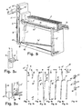
- FIG. 1 shows a schematic plan view of an automatic take-in machine according to the invention
- FIG. 2 shows the detailed view of a heddle for the re-entry machine of FIG. 1
- - FIG. 3 shows the detailed view of a heald in the heald frame corresponding with the thread passed through the eyelet
- FIG. 4 shows the schematic view of the heald pack and the comb after tuck-in, passage and tacking
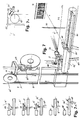
- FIG. 5 shows the feed group of the pieces of wire
- FIG. 5A shows the detailed view of the gunner wire for the group in Fig. 5
- - FIG. 5B shows the detailed view of the derailleur for the group in FIG. 5
- FIGS. 6A-6H show, schematically, the phases of forming a piece of wire folded in half and of passing the two wires; detail of the functioning of the wire clamp with shears for the group of FIG. 5;
- - FIG. 6L schematically represents, the detail of the operation of the wire clamp with shears for the group of FIG. 5;
- FIG. 7 shows the detailed view of the wire clamp and the loading device for the group in FIG. 5;
- FIG. 7A shows the operation of the wire clamp and the diverter for the group of FIG.
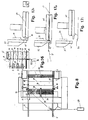
- FIG. 9 shows the detailed view of a beam selector
- - FIG. 10 shows the sectional view along line AA of FIG. 9
- - FIG. 11 shows the side view of the selector of FIG. 9
- - FIG. 12A-12G represent, in succession, the phases of selection of a boom with the selector of FIG. 9
- FIG. 13 shows the detailed front view of a wedge-shaped selector
- - FIG. 14 shows the side view of the selector of FIG. 13
- FIG. 15A shows the sectional view along line AA of FIG. 13; - FIG.
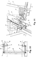
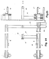
- FIG. 22 shows the detailed view of the control of the needle of the switch of FIG. 21; - FIG. 23 shows the overview of the actuation means; - FIG. 24 shows the detailed view of the beam transport means; - FIG. 25 shows the side view of the means of FIG. 24.
- the two parts of each piece of wire have approximately the same length and extend so as to present an approximately vertical section and an approximately horizontal section, the head and tail portions. of each piece belonging to said second section.
- said threading 5 ' provides for tensioning a cord 54' inside the loop formed by each piece of wire and to move alternately up and down, relative to the plane of tuck-in, a second cord 54 stretched perpendicular to the wires 5 'of tuck-in, with inversion of the movement with each wire 5' tucked in: said cord 54 being movable longitudinally, with distance from the retraction head, or otherwise immobile longitudinally.
- a closed ring belt extending horizontally and whose movement is such that its lower part, on which are placed on the pieces of wire, moves from left to right in Fig. 5.
- the group for positioning the comb 16 relative to the passette 17, and with reference to FIGS. 18.19A of the accompanying drawings, includes: -a comb 16 mounted with the teeth in a vertical position on a carriage 35 free to slide on a horizontal track 56, parallel to the heddle frames 2 and whose displacement forward intermittent is obtained from an electric motor 34 with the cooperation of a clutch 33 and so that the clutch 33, when the electric motor 34 is deactivated, first of all releases the carriage 35 with the comb 16 during the separation of the teeth by the spacer 32, then blocks the carriage 35 during the passage of the wire and the retraction of the spacer 32, and finally, when the electric motor 34 is actuated, allows the carriage to be moved forward 35 with a pitch equal to that of the teeth of the comb 16.
- the operation is as follows.
- the service selector 10 takes a rail 30 from one of the channels 11 and the vice 65 positions it with the eyelet 25 opposite the slot 97 'of the corresponding stop 97; simultaneously, the comb 16 is positioned with the teeth to pass opposite the free end of the passette 17 and with the spacer element 32 inserted between these teeth; after which the passette 17, in its forward stroke, is introduced between the teeth of the comb thus spaced apart, then the slot of the stop 97 and finally in the eyelet 25 of the stringer 30 until it reaches and takes the wire 5 ' which is provided to it by the display element of the wire 48; in the return stroke, the passette 17 retracts the heald and passes through the comb, after which it is stripped of the thread by the thread removal element 19.
- the needle 14 of the 'switch 22, corresponding to the selector 10 which took the heald 30, predisposes the transfer thereof to the heald frame 2 of the corresponding group of frames which is predetermined by the handing-over and the pusher 73, which is associated with the pusher 73, the vice 65, the element for removing the wire 19 and the passette 17 is obtained by means of a variable speed motor 120 with interposition of the belt 121, the cams 111,114,116 and the rocker arms 104- 106 as illustrated in Figs. 23 to 25 of the accompanying drawings.
Landscapes
- Engineering & Computer Science (AREA)
- Textile Engineering (AREA)
- Auxiliary Weaving Apparatuses, Weavers' Tools, And Shuttles (AREA)
- Warping, Beaming, Or Leasing (AREA)
- Manufacture, Treatment Of Glass Fibers (AREA)
- Load-Engaging Elements For Cranes (AREA)
- Pressure Welding/Diffusion-Bonding (AREA)
- Grinding Of Cylindrical And Plane Surfaces (AREA)
- Spinning Or Twisting Of Yarns (AREA)
- Looms (AREA)
- Treatment Of Fiber Materials (AREA)
Claims (14)
- Verfahren zum automatischen Einziehen von Kettfäden, das folgende Schritte umfaßt:
Zuführen der Einziehfäden,
Einziehen der Litzen und Hindurchführen durch den Webkamm, und
Auswahl und Wiedereinsetzen der einzelnen Litzen, dadurch gekennzeichnet, daß das Zuführen der Einziehfäden folgende Schritte umfaßt:- Ausbilden von doppelt gefalteten Fadenstücken (5', 5') ausgehend vom Faden (5) wenigstens eines Fadenspeichers, wie z.B. einer Spule (46), und Hindurchführen des Kopfes und danach des Endstückes eines jeden Stücks durch eine oder mehrere entsprechende Litzen (30) und zwischen den entsprechenden Zähnen des Webkamms (16);- Einflechten und Spannen der so gebildeten und hindurchgeführten Fäden (5'),- fortschreitendes Entfernen der verschiedenen auf diese Weise hindurchgeführten und eingeflochtenen Fäden (5'), vom Einziehkopf,daß das Hindurchführen durch den Webkamm den Schritt umfaßt, daß der Webkamm (16) dadurch automatisch richtig positioniert wird, daß eine erste vorausgehende, in einer Richtung ausgeführte Verschiebung mit konstanter Schrittweite erfolgt, worauf gegebenenfalls einen zweite entsprechende Verschiebung folgt oder nicht, um eine genaue Ausrichtung zwischen der Vertikalachse eines jeden zwischen zwei Zähnen des Webkamms eingeschlossenen Zwischenraums und der Vertikalachse des Einziehnadelabschnittes zu erzielen,
daß die Auswahl der einzuziehenden Litzen den Schritt umfaßt, daß die Litzen in mehreren Gruppen bündelweise gespeichert werden, und
daß das Wiedereinsetzen den Schritt umfaßt, daß die eingezogenen Litzen direkt aus der Bahn (11) des entsprechenden Speichers in die Bahn (22) einer entsprechenden Gruppe von Litzenrahmen übergeführt und dabei ständig geführt gehalten werden. - Verfahren nach Anspruch 1, dadurch gekenn zeichnet, daß die beiden Teile (5'), die die Fadenstücke bilden, ungefähr die gleiche Länge besitzen, wobei ein Abschnitt vorzugsweise im wesentlichen vertikal und ein Abschnitt im wesentlichen horizontal verläuft.
- Verfahren nach Anspruch 1, dadurch gekenn zeichnet, daß besagtes Einflechten den Schritt umfaßt, daß eine Schnur (54') im Inneren der Schlinge gespannt wird, die von jedem Fadenstück gebildet wird, und daß mit einer hin- und hergehenden, bezüglich der Einziehebene vertikalen Bewegung das Ende einer zweiten Schnur (54) verschoben wird, die senkrecht zum Einziehfaden (5') gespannt ist, wobei die Bewegung nach dem Einziehen eines jeden Fadens (5') umgekehrt wird.
- Verfahren nach Anspruch 3, dadurch gekenn zeichnet, daß der Schritt vorgesehen ist, besagte Spannschnur (54) in Längsrichtung, in Richtung vom Einziehkopf weg zu verschieben oder nicht.
- Maschine zum automatischen Einziehen von Kettfäden mit einer Zuführanordnung für die Einziehfäden, einer Zuführanordnung für die einzuziehenden Litzen, einer Positionieranordnung für den Webkamm, einer Anordnung zum Einziehen der Litzen und zum Hindurchführen durch den Webkamm, einer Anordnung zum Wiedereinsetzen der eingezogenen Litzen, dadurch gekennzeich net, daß die Zuführanordnung für die Einziehfäden Einrichtungen umfaßt, die dazu dienen, der Einziehnadel (17) den Kopf und danach das Endstück der doppelt gefalteten Fadenstücke (5', 5'), die von wenigstens einem Fadenspeicher, wie z.B. einer Spule oder einer Spindel (46) erhalten werden, vermittels einer Fadenzieheinrichtung (21) und einer Fadenklemme (23) mit einer Schere (23') zuzuführen, mit zwei horizontalen Gewindestangen (42, 42'), die sich in unterschiedlicher Höhe befinden und sich in Übereinstimmung drehen, um getrennt die beiden Teile (5', 5') der Fadenstücke zu tragen und sie in fortschreitender Weise vom Einziehkopf zu entfernen; mit einer Ausrückvorrichtung (40), die dazu dient, die in Ausbildung befindlichen Fadenstücke von der besagten Fadenzieheinrichtung (21) zur unteren Gewindestange (42) zu übertragen;
daß die besagte Zuführanordnung für die einzuziehenden Litzen (30) ein Mehrfachmagazin mit mehreren Seite an Seite angeordneten Bahnen (11) für die Bewegung der aufgehängten Litzen (30) umfaßt, wobei jede Bahn bis zu einer entsprechenden Gruppe von mehreren Litzenrahmen (2) verlängert und eine eine entsprechende Mehrfachweiche (22) mit einer Weichenzunge (14) zwischengeschaltet ist, und
daß die Positionieranordnung für den Webkamm einen Schlitten (35) umfaßt, der den Webkamm (16) mit senkrechten Zähnen so trägt, daß er frei ist, sich auf einer horizontalen und zu besagten Rahmen (2) parallelen Bahn während des durch eine Spreizvorrichtung (32) bewirkten Öffnens der Zähne zu verschieben, und dessen intermittierende Vorwärtsverschiebung mit einer Kupplung (33) von einem Elektromotor (34) abgeleitet wird. - Maschine nach Anspruch 5, dadurch gekenn zeichnet, daß die Fadenzieheinrichtung (21) an einem ringförmig geschlossenen Riemen (8), der sich senkrecht erstreckt, in der Weise befestigt ist, daß sie den Faden (5) zwischen dem Speicher (46) und der Fadenklemme (23) in der Nähe des Anfangs ihrer nach unten gerichteten Bewegung abfängt, und daß die Ausrückvorrichtung (40) ein Keil mit oben liegender Spitze ist, der eine geneigte Seite aufweist, die zum freien Ende der unteren Gewindestange (42) hin orientiert ist und sich bis unter dieses freie Ende erstreckt, wobei sich der Keil an einer Stelle befindet, die es ermöglicht, daß er den von der Fadenzieheinrichtung (21) gehaltenen Faden (5) in der Nähe des Endes ihrer nach unten gerichteten Bewegung abfängt.
- Maschine nach den Ansprüchen 5 und 6, dadurch ge kennzeichnet, daß die besagte untere Gewindestange (42) frei vorragend so angeordnet ist, daß sich ihr freies Ende in geringem Abstand von besagtem Zahnriemen (8) in der Nähe des Endes seines sich nach unten bewegenden Abschnitts befindet.
- Maschine nach Anspruch 7, dadurch gekenn zeichnet, daß an besagter unterer Gewindestange (42) eine darüberliegende Halteschnur (54') so befestigt und gespannt ist, daß sie sich im Inneren der von den Fadenstücken (5', 5') gebildeten Schlaufe befindet.
- Maschine nach den Ansprüchen 5 bis 8, dadurch ge kennzeichnet, daß sie anstelle der besagten unteren Gewindestange (42) einen ringförmig geschlossenen, sich horizontal erstreckenden Riemen umfaßt, dessen Bewegung besagte Fadenstücke (5, 5'), die auf seinem unteren Teil reitend aufsitzen, mitnimmt und von besagter Ausrückvorrichtung (40) wegbewegt.
- Maschine nach Anspruch 5, dadurch gekenn zeichnet, daß die besagte Anordnung zum Zuführen der Einziehfäden unter anderem ein Element (49) umfaßt, das so ausgebildet ist, daß es den Faden (5') der Einziehnadel (17) mit einer hin- und hergehenden Bewegung in der Weise darbietet, daß sich das aktive Ende in einer horizontalen Ebene oberhalb der Einziehnadel (17) und in einer solchen Position befindet, daß es während seiner aktiven Bewegung den ersten Teil des Stücks (5') des Fadens in der Zone zwischen der Fadenzieheinrichtung (21) und der Fadenklemme (23) bzw. den zweiten Teil des Fadenstücks in der Zone zwischen der Fadenklemme (23) und der unteren Gewindestange (42) erfaßt.
- Maschine nach Anspruch 5, dadurch gekenn zeichnet, daß besagte Anordnung zum Zuführen der Einziehfäden unter anderem Mittel zum Durchflechten der Fäden (5') mit einem Kurbelmechanismus (51) mit einer hin- und hergehenden Bewegung um eine horizontale Achse mit einem vorkragenden Arm umfaßt, dessen eines Ende an einer Schnur (54) und dessen anderes Ende an einem Ständer (9') befestigt ist, der die Gewindestangen (42, 42') trägt, oder aber beweglich ist, wobei ein sich Wegbewegen vom Einziehkopf erfolgt.
- Maschine nach Anspruch 5, dadurch gekenn zeichnet, daß die Anordnung zum Zuführen der Einziehfäden unter anderem eine Ablenkwippe (49) umfaßt, die dazu ausgebildet ist, jeden Faden (5') nach dem Einziehen vom Einziehkopf wegzubewegen.
- Maschine nach den Ansprüchen 5 und 12, dadurch gekennzeichnet, daß besagte Anordnung zum Zuführen der Einziehfäden unter anderem Mittel umfaßt, die dazu dienen, mit einem zwei Abschnitte (50, 50') umfassenden Bürstenspanner die Einziehfäden (5') zu spannen, wobei die Borsten des Bürstenspanners tangentiell auf die obere Gewindestange (42') einwirken, und der Abschnitt (50') unter der Steuerung der Ablenkwippe (49) anhebbar ist.
- Maschine nach Anspruch 5, dadurch gekenn zeichnet, daß jede Weichenzunge (14) der besagten Weichenanordnungen (22) vermittels eines Scharniers an der entsprechenden Schiene der betreffenden Bahn (11) der Litzenspeicher (30) angelenkt ist, und daß ihre Oszillationsbewegung von einem entsprechenden elektrischen Schrittmotor (98) vermittels einer Transmission mit Riemen (95) und Riemenscheiben (94) sowie einem Schwinghebel (74) abgeleitet ist.
Priority Applications (1)
| Application Number | Priority Date | Filing Date | Title |
|---|---|---|---|
| AT90830374T ATE104373T1 (de) | 1989-09-29 | 1990-08-10 | Verfahren und vorrichtung zum automatischen einziehen von kettfaeden. |
Applications Claiming Priority (2)
| Application Number | Priority Date | Filing Date | Title |
|---|---|---|---|
| IT953489 | 1989-09-29 | ||
| IT8909534A IT1233750B (it) | 1989-09-29 | 1989-09-29 | Metodo di incorsatura automatica e macchina per attuare il detto metodo |
Publications (2)
| Publication Number | Publication Date |
|---|---|
| EP0421943A1 EP0421943A1 (de) | 1991-04-10 |
| EP0421943B1 true EP0421943B1 (de) | 1994-04-13 |
Family
ID=11131786
Family Applications (1)
| Application Number | Title | Priority Date | Filing Date |
|---|---|---|---|
| EP90830374A Expired - Lifetime EP0421943B1 (de) | 1989-09-29 | 1990-08-10 | Verfahren und Vorrichtung zum automatischen Einziehen von Kettfäden |
Country Status (8)
| Country | Link |
|---|---|
| US (1) | US5136762A (de) |
| EP (1) | EP0421943B1 (de) |
| JP (1) | JP2942611B2 (de) |
| AT (1) | ATE104373T1 (de) |
| DE (1) | DE69008100T2 (de) |
| DK (1) | DK0421943T3 (de) |
| ES (1) | ES2055403T3 (de) |
| IT (1) | IT1233750B (de) |
Families Citing this family (18)
| Publication number | Priority date | Publication date | Assignee | Title |
|---|---|---|---|---|
| CH682577A5 (de) * | 1990-09-17 | 1993-10-15 | Zellweger Uster Ag | Vorrichtung zur Handhabung von Litzen oder Lamellen in einer Kettfadeneinziehmaschine. |
| CH682929A5 (de) * | 1991-02-22 | 1993-12-15 | Zellweger Uster Ag | Vorrichtung zum Einziehen von Kettfäden in ein Webblatt. |
| TW216808B (de) * | 1991-10-24 | 1993-12-01 | Teijin Ltd | |
| CH687714A5 (de) * | 1993-09-13 | 1997-01-31 | Stsubli Ag Zweigwerk Sargans | Vorrichtung zur Handhabung von Litzen fuer Kettfadeneinziehmaschinen. |
| CH690783A5 (de) * | 1995-12-21 | 2001-01-15 | Staeubli Ag Zweigwerk Sargans | Verfahren und Vorrichtung zum Einziehen von Kettfäden. |
| IT1286547B1 (it) * | 1996-02-09 | 1998-07-15 | El & M S P A | Metodo e dispositivo per la passatura dei fili attraverso i denti di un pettine doppio in una macchina incorsatrice automatica |
| DE50111691D1 (de) * | 2000-06-20 | 2007-02-01 | Staeubli Ag Pfaeffikon | Vorrichtung und verfahren zur einführung von kettfäden in ein webblatt |
| US20030121131A1 (en) * | 2001-12-03 | 2003-07-03 | Japan Storage Battery Co., Ltd. | Apparatus for producing a grid for a battery plate, and method of producing the same |
| EP2199443B1 (de) * | 2008-12-19 | 2016-03-16 | Stäubli AG Pfäffikon | Mobile Einzieheinheit |
| WO2010150582A1 (ja) * | 2009-06-25 | 2010-12-29 | 株式会社藤堂製作所 | 種糸としての経糸の自動引込み装置、及び種糸としての経糸の自動引込み方法 |
| EP2730687B1 (de) * | 2012-11-08 | 2015-09-16 | Groz-Beckert KG | Litze für eine Webmaschine, insbesondere eine Rundwebmaschine |
| CN103590172B (zh) * | 2013-11-25 | 2015-06-03 | 天津工业大学 | 碳纤维多层角联织机的收纱装置 |
| CN106087210B (zh) * | 2016-07-29 | 2017-10-24 | 江阴市通源纺机有限公司 | 自动纱线穿综设备 |
| PT3754071T (pt) * | 2019-06-17 | 2022-05-11 | Groz Beckert Kg | Método, dispositivo, carro móvel e máquina de remeter |
| ES2951844T3 (es) | 2019-06-17 | 2023-10-25 | Groz Beckert Kg | Dispositivo y procedimiento para manejar elementos de marco de lizos |
| ES2976198T3 (es) | 2019-06-19 | 2024-07-26 | Groz Beckert Kg | Dispositivo y procedimiento para manipular elementos de tejeduría |
| EP3754073B1 (de) * | 2019-06-19 | 2022-03-02 | Groz-Beckert KG | Vorrichtung und verfahren zur handhabung von webgeschirrelementen |
| ES2913413T3 (es) * | 2019-06-19 | 2022-06-02 | Groz Beckert Kg | Dispositivo para manipular accesorios de tejeduría y máquina de remetido |
Family Cites Families (8)
| Publication number | Priority date | Publication date | Assignee | Title |
|---|---|---|---|---|
| US2828527A (en) * | 1954-08-18 | 1958-04-01 | Zellweger Uster Ag | Device for presenting healds to a hook for drawing-in warp threads |
| US3121936A (en) * | 1959-08-31 | 1964-02-25 | Zellwerger Ltd | Method and apparatus for automatically threading the healds of a loom |
| CH479735A (de) * | 1968-12-20 | 1969-10-15 | Zellweger Uster Ag | Webketteneinziehmaschine |
| FR2076681A5 (en) * | 1970-01-23 | 1971-10-15 | Blin Et Blin | Warping machine for loom - supplies short lengths of warp yarn |
| GB1352332A (en) * | 1970-02-03 | 1974-05-08 | Wool Ind Res Assoc | Production of woven structures |
| US3867745A (en) * | 1972-06-12 | 1975-02-25 | Barber Colman Co | Method for drawing in warp threads |
| US3787938A (en) * | 1972-06-12 | 1974-01-29 | Barber Colman Co | Method and apparatus for drawing in warp threads |
| JPS6420359A (en) * | 1987-07-10 | 1989-01-24 | Teijin Seiki Co Ltd | Heald transfer apparatus |
-
1989
- 1989-09-29 IT IT8909534A patent/IT1233750B/it active
-
1990
- 1990-08-10 DK DK90830374.6T patent/DK0421943T3/da active
- 1990-08-10 ES ES90830374T patent/ES2055403T3/es not_active Expired - Lifetime
- 1990-08-10 EP EP90830374A patent/EP0421943B1/de not_active Expired - Lifetime
- 1990-08-10 AT AT90830374T patent/ATE104373T1/de active
- 1990-08-10 DE DE69008100T patent/DE69008100T2/de not_active Expired - Fee Related
- 1990-09-26 US US07/588,663 patent/US5136762A/en not_active Expired - Lifetime
- 1990-09-28 JP JP2262941A patent/JP2942611B2/ja not_active Expired - Fee Related
Also Published As
| Publication number | Publication date |
|---|---|
| DK0421943T3 (da) | 1994-08-08 |
| US5136762A (en) | 1992-08-11 |
| EP0421943A1 (de) | 1991-04-10 |
| ES2055403T3 (es) | 1994-08-16 |
| JPH03227434A (ja) | 1991-10-08 |
| DE69008100T2 (de) | 1994-11-17 |
| JP2942611B2 (ja) | 1999-08-30 |
| IT8909534A0 (it) | 1989-09-29 |
| DE69008100D1 (de) | 1994-05-19 |
| ATE104373T1 (de) | 1994-04-15 |
| IT1233750B (it) | 1992-04-14 |
Similar Documents
| Publication | Publication Date | Title |
|---|---|---|
| EP0421943A1 (de) | Verfahren und Vorrichtung zum automatischen Einziehen von Kettfäden | |
| KR100388656B1 (ko) | 전자제어샘플정경기,정경방법및회전식크릴 | |
| FR2553314A1 (fr) | Methode et machine de fabrication d'etriers | |
| FR2930950A1 (fr) | Machine de rentrage | |
| FR2554463A1 (fr) | Sangles tissees avec retrecissements transversaux localises, obtenues sur metiers automatiques a faucilles et leur procede de realisation | |
| BE1003884A5 (fr) | Procede de tuftage et dispositif pour la mise en oeuvre de ce procede. | |
| RU2051236C1 (ru) | Швейная машина | |
| FR2524014A1 (fr) | Dispositif pour dissocier et preparer des fils de chaine en vue de leur insertion dans les lices et lamelles de metiers a tisser | |
| FR2597290A1 (fr) | Procede et appareil de fabrication de faisceaux de conducteurs | |
| US3583735A (en) | Machine for binding and tying up packages or bundles | |
| DE602005001359T2 (de) | Nähmaschine mit automatischem Einfädler | |
| FR2785914A1 (fr) | Dispositif d'amenee d'une couche de fils multicouche, multi-axiale a l'emplacement de tricotage d'un metier a tricoter chaine | |
| FR2678649A1 (fr) | Machine a broder. | |
| FR2714396A1 (fr) | Dispositif de sélection de trame sur un métier à tisser. | |
| US3777682A (en) | Machine for sewing up netting webs | |
| CH571605A5 (en) | Pile fabric mfr - partic carpets,by the application of pile or nap fibres to an adhesive-coated substrate | |
| JPH0813303A (ja) | 編網機の下鉤駆動装置 | |
| US4723798A (en) | Automatic machines for tying various types of sausages | |
| FR2580000A1 (de) | ||
| US6671937B1 (en) | Rotary creel for electronically controlled sample warper | |
| BE1012809A4 (fr) | Systeme selecteur de fil axminster. | |
| FR2792340A1 (fr) | Mecanisme d'echange de fil dans un ourdissoir d'echantillonnage commande electroniquement | |
| US1823911A (en) | Embroidery machine | |
| CA1258363A (fr) | Dispositifs regulateurs de fils de chaine et de thermo-fixation des rubans a boucles auto- aggrippantes, adaptables au metier a tricoter | |
| FR2504563A1 (fr) | Procede de tricotage d'un article a refermer sur lui-meme, et machine a tricoter pour la mise en oeuvre du procede |
Legal Events
| Date | Code | Title | Description |
|---|---|---|---|
| PUAI | Public reference made under article 153(3) epc to a published international application that has entered the european phase |
Free format text: ORIGINAL CODE: 0009012 |
|
| AK | Designated contracting states |
Kind code of ref document: A1 Designated state(s): AT BE CH DE DK ES FR GB GR IT LI NL SE |
|
| 17P | Request for examination filed |
Effective date: 19910504 |
|
| 17Q | First examination report despatched |
Effective date: 19930401 |
|
| GRAA | (expected) grant |
Free format text: ORIGINAL CODE: 0009210 |
|
| AK | Designated contracting states |
Kind code of ref document: B1 Designated state(s): AT BE CH DE DK ES FR GB GR IT LI NL SE |
|
| REF | Corresponds to: |
Ref document number: 104373 Country of ref document: AT Date of ref document: 19940415 Kind code of ref document: T |
|
| REF | Corresponds to: |
Ref document number: 69008100 Country of ref document: DE Date of ref document: 19940519 |
|
| ITF | It: translation for a ep patent filed | ||
| GBT | Gb: translation of ep patent filed (gb section 77(6)(a)/1977) |
Effective date: 19940620 |
|
| REG | Reference to a national code |
Ref country code: DK Ref legal event code: T3 |
|
| REG | Reference to a national code |
Ref country code: ES Ref legal event code: FG2A Ref document number: 2055403 Country of ref document: ES Kind code of ref document: T3 |
|
| REG | Reference to a national code |
Ref country code: GR Ref legal event code: FG4A Free format text: 3012355 |
|
| EAL | Se: european patent in force in sweden |
Ref document number: 90830374.6 |
|
| PLBE | No opposition filed within time limit |
Free format text: ORIGINAL CODE: 0009261 |
|
| STAA | Information on the status of an ep patent application or granted ep patent |
Free format text: STATUS: NO OPPOSITION FILED WITHIN TIME LIMIT |
|
| 26N | No opposition filed | ||
| REG | Reference to a national code |
Ref country code: CH Ref legal event code: PUE Owner name: EL & M S.P.A. TRANSFER- PATCORP S.A. Ref country code: CH Ref legal event code: PFA Free format text: EL & M S.R.L. TRANSFER- EL & M S.P.A. |
|
| NLS | Nl: assignments of ep-patents |
Owner name: PATCORP S.A. |
|
| NLT1 | Nl: modifications of names registered in virtue of documents presented to the patent office pursuant to art. 16 a, paragraph 1 |
Owner name: EL.& M. S.P.A. |
|
| REG | Reference to a national code |
Ref country code: GB Ref legal event code: 732E |
|
| REG | Reference to a national code |
Ref country code: FR Ref legal event code: CD Ref country code: FR Ref legal event code: TP Ref country code: FR Ref legal event code: CJ |
|
| REG | Reference to a national code |
Ref country code: ES Ref legal event code: PC2A |
|
| PGFP | Annual fee paid to national office [announced via postgrant information from national office to epo] |
Ref country code: GB Payment date: 19980804 Year of fee payment: 9 |
|
| PGFP | Annual fee paid to national office [announced via postgrant information from national office to epo] |
Ref country code: NL Payment date: 19980817 Year of fee payment: 9 |
|
| PGFP | Annual fee paid to national office [announced via postgrant information from national office to epo] |
Ref country code: DK Payment date: 19980819 Year of fee payment: 9 |
|
| PGFP | Annual fee paid to national office [announced via postgrant information from national office to epo] |
Ref country code: AT Payment date: 19980825 Year of fee payment: 9 |
|
| PGFP | Annual fee paid to national office [announced via postgrant information from national office to epo] |
Ref country code: GR Payment date: 19980831 Year of fee payment: 9 Ref country code: SE Payment date: 19980831 Year of fee payment: 9 |
|
| PGFP | Annual fee paid to national office [announced via postgrant information from national office to epo] |
Ref country code: BE Payment date: 19981016 Year of fee payment: 9 |
|
| PGFP | Annual fee paid to national office [announced via postgrant information from national office to epo] |
Ref country code: CH Payment date: 19981119 Year of fee payment: 9 |
|
| BECH | Be: change of holder |
Free format text: 980519 S.A. *PATCORP |
|
| PG25 | Lapsed in a contracting state [announced via postgrant information from national office to epo] |
Ref country code: AT Free format text: LAPSE BECAUSE OF NON-PAYMENT OF DUE FEES Effective date: 19990810 Ref country code: GB Free format text: LAPSE BECAUSE OF NON-PAYMENT OF DUE FEES Effective date: 19990810 |
|
| PG25 | Lapsed in a contracting state [announced via postgrant information from national office to epo] |
Ref country code: SE Free format text: THE PATENT HAS BEEN ANNULLED BY A DECISION OF A NATIONAL AUTHORITY Effective date: 19990830 |
|
| PG25 | Lapsed in a contracting state [announced via postgrant information from national office to epo] |
Ref country code: GR Free format text: LAPSE BECAUSE OF NON-PAYMENT OF DUE FEES Effective date: 19990831 Ref country code: LI Free format text: LAPSE BECAUSE OF NON-PAYMENT OF DUE FEES Effective date: 19990831 Ref country code: CH Free format text: LAPSE BECAUSE OF NON-PAYMENT OF DUE FEES Effective date: 19990831 Ref country code: DK Free format text: LAPSE BECAUSE OF NON-PAYMENT OF DUE FEES Effective date: 19990831 Ref country code: BE Free format text: LAPSE BECAUSE OF NON-PAYMENT OF DUE FEES Effective date: 19990831 |
|
| BERE | Be: lapsed |
Owner name: S.A. PATCORP Effective date: 19990831 |
|
| PG25 | Lapsed in a contracting state [announced via postgrant information from national office to epo] |
Ref country code: NL Free format text: LAPSE BECAUSE OF NON-PAYMENT OF DUE FEES Effective date: 20000301 |
|
| GBPC | Gb: european patent ceased through non-payment of renewal fee |
Effective date: 19990810 |
|
| REG | Reference to a national code |
Ref country code: CH Ref legal event code: PL |
|
| REG | Reference to a national code |
Ref country code: DK Ref legal event code: EBP |
|
| EUG | Se: european patent has lapsed |
Ref document number: 90830374.6 |
|
| NLV4 | Nl: lapsed or anulled due to non-payment of the annual fee |
Effective date: 20000301 |
|
| REG | Reference to a national code |
Ref country code: ES Ref legal event code: PC2A |
|
| REG | Reference to a national code |
Ref country code: FR Ref legal event code: TP |
|
| PG25 | Lapsed in a contracting state [announced via postgrant information from national office to epo] |
Ref country code: IT Free format text: LAPSE BECAUSE OF NON-PAYMENT OF DUE FEES;WARNING: LAPSES OF ITALIAN PATENTS WITH EFFECTIVE DATE BEFORE 2007 MAY HAVE OCCURRED AT ANY TIME BEFORE 2007. THE CORRECT EFFECTIVE DATE MAY BE DIFFERENT FROM THE ONE RECORDED. Effective date: 20050810 |
|
| PGFP | Annual fee paid to national office [announced via postgrant information from national office to epo] |
Ref country code: DE Payment date: 20080822 Year of fee payment: 19 Ref country code: ES Payment date: 20080828 Year of fee payment: 19 |
|
| PGFP | Annual fee paid to national office [announced via postgrant information from national office to epo] |
Ref country code: FR Payment date: 20080813 Year of fee payment: 19 |
|
| PGRI | Patent reinstated in contracting state [announced from national office to epo] |
Ref country code: IT Effective date: 20090401 |
|
| REG | Reference to a national code |
Ref country code: ES Ref legal event code: PC2A |
|
| PGFP | Annual fee paid to national office [announced via postgrant information from national office to epo] |
Ref country code: IT Payment date: 20080729 Year of fee payment: 19 |
|
| REG | Reference to a national code |
Ref country code: FR Ref legal event code: TP |
|
| REG | Reference to a national code |
Ref country code: FR Ref legal event code: ST Effective date: 20100430 |
|
| PG25 | Lapsed in a contracting state [announced via postgrant information from national office to epo] |
Ref country code: FR Free format text: LAPSE BECAUSE OF NON-PAYMENT OF DUE FEES Effective date: 20090831 Ref country code: DE Free format text: LAPSE BECAUSE OF NON-PAYMENT OF DUE FEES Effective date: 20100302 |
|
| REG | Reference to a national code |
Ref country code: ES Ref legal event code: FD2A Effective date: 20090811 |
|
| PG25 | Lapsed in a contracting state [announced via postgrant information from national office to epo] |
Ref country code: IT Free format text: LAPSE BECAUSE OF NON-PAYMENT OF DUE FEES Effective date: 20090810 |
|
| PG25 | Lapsed in a contracting state [announced via postgrant information from national office to epo] |
Ref country code: ES Free format text: LAPSE BECAUSE OF NON-PAYMENT OF DUE FEES Effective date: 20090811 |