EP0421948B1 - An operating linkage for the gearbox of a commercial vehicle with a safety system for preventing the gears from becoming disengaged - Google Patents
An operating linkage for the gearbox of a commercial vehicle with a safety system for preventing the gears from becoming disengaged Download PDFInfo
- Publication number
- EP0421948B1 EP0421948B1 EP19900830408 EP90830408A EP0421948B1 EP 0421948 B1 EP0421948 B1 EP 0421948B1 EP 19900830408 EP19900830408 EP 19900830408 EP 90830408 A EP90830408 A EP 90830408A EP 0421948 B1 EP0421948 B1 EP 0421948B1
- Authority
- EP
- European Patent Office
- Prior art keywords
- connecting rod
- pivot axis
- edge
- slider
- gears
- Prior art date
- Legal status (The legal status is an assumption and is not a legal conclusion. Google has not performed a legal analysis and makes no representation as to the accuracy of the status listed.)
- Expired - Lifetime
Links
- 230000005540 biological transmission Effects 0.000 claims description 8
- 239000002184 metal Substances 0.000 claims description 3
- 230000006835 compression Effects 0.000 description 1
- 238000007906 compression Methods 0.000 description 1
- 230000007935 neutral effect Effects 0.000 description 1
Images

Classifications
-
- F—MECHANICAL ENGINEERING; LIGHTING; HEATING; WEAPONS; BLASTING
- F16—ENGINEERING ELEMENTS AND UNITS; GENERAL MEASURES FOR PRODUCING AND MAINTAINING EFFECTIVE FUNCTIONING OF MACHINES OR INSTALLATIONS; THERMAL INSULATION IN GENERAL
- F16H—GEARING
- F16H61/00—Control functions within control units of change-speed- or reversing-gearings for conveying rotary motion ; Control of exclusively fluid gearing, friction gearing, gearings with endless flexible members or other particular types of gearing
- F16H61/26—Generation or transmission of movements for final actuating mechanisms
-
- F—MECHANICAL ENGINEERING; LIGHTING; HEATING; WEAPONS; BLASTING
- F16—ENGINEERING ELEMENTS AND UNITS; GENERAL MEASURES FOR PRODUCING AND MAINTAINING EFFECTIVE FUNCTIONING OF MACHINES OR INSTALLATIONS; THERMAL INSULATION IN GENERAL
- F16H—GEARING
- F16H59/00—Control inputs to control units of change-speed- or reversing-gearings for conveying rotary motion
- F16H59/02—Selector apparatus
- F16H59/04—Ratio selector apparatus
- F16H59/042—Ratio selector apparatus comprising a final actuating mechanism
Definitions
- the present invention relates to an operating linkage for the gearboxes of commercial vehicles comprising the features as outlined in the preamble of claim 1.
- Such an operating linkage is known from DE-C 35 19 749.
- the object of the present invention is to further develop a generic linkage of the type specified at the beginning of the description which is simply and cheaply without increasing the loads applied to the gear lever by the user.
- the linkage preferably includes a push rod supported slidably by the connecting rod and parallel thereto, a cam element fixed to the support structure and having a profiled edge parallel to the plane of articulation of the connecting rod, the edge having a first portion whose average radial distance from the pivot axis of the connecting rod is greater than the average radial distance therefrom of two adjacent second portions of the edge connected to the first portion, and a spring interposed between the push rod and the connecting rod and adapted to urge the push rod against the edge of the cam element, the pivoting of the connecting rod compressing the spring when the push rod slides from one of the two second edge portions of the cam element towards the first portion.
- the safety system operates only during the stage of disengagement of the gears, whilst the loads on the gear lever remain unchanged during the engagement stage.
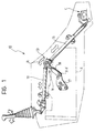
- a linkage, generally indicated 10, for operating the gearbox C of a commercial vehicle comprises first and second transmission levers 11 and 12 interposed between the selector of the gearbox C and the manual gear lever, indicated L in the drawings, situated in the driver's cab of the vehicle.
- a linkage of this type which includes a joint 13 between the levers 11 and 12 comprising a spherical support element rotatable within a tubular body which forms part of the cross member of the joint, is described and illustrated in European Patent Application EP-A-0 376 902 filed by the Applicant and to which reference is made (published on 04/07/90).
- the joint 13 between the transmission levers 11 and 12 is formed in correspondence with a connecting rod 16 interposed between a mounting 17 fixed to the structure A of the vehicle, in this case, the engine block, and the articulation joint between the transmission levers.
- the connecting rod 16 pivots about the horizontal axis X-X of the connecting rod, its pivoting movement being indicated by the arrow R in Figure 1.
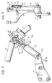
- an elongate plate-like arm 18 is also fixed to the mounting 17 and has a first end 18a keyed rigidly to the mounting 17 in correspondence with the lower end of the connecting rod 16 (with reference to the installed configuration of the linkage) and a second end 18b with a substantially V-shaped cam profile 19 defining a central portion 19a and two side portions 19b.
- the average radial distance of the central portion 19a of the cam 19 from the axis of rotation X-X of the connecting rod 16 is greater than the average distance therefrom of the adjacent portions 19b connected thereto.
- the connecting rod 16 has a tubular seat 21 which has an axis Y-Y substantially parallel to the connecting rod itself and in which is slidable a push rod 22 with a sperhical end 22a in frontal contact with the cam profile 19 at the end 18b of the arm 18.
- a helical spring 24 is interposed between the push rod 22 and a screw adjustment device 23 for urging the end 22a of the push rod 22 against the cam 19 with a predetermined force.
- the gearbox is in neutral, which is the condition of maximum compression of the spring 24 by the cam profile 19.
- the connecting rod 16 pivots clockwise or anticlockwise (with reference to Figures 1 and 2) so that the push rod 22a slides over the cam profile 19 towards the portion 19b of that profile and progressively "unloads” the spring 24.
- the force required for the push rod 22 to compress the spring 24 again by sliding along on the cam profile 19 prevents any accidental disengagement of the gears.
- the arm 18 has two holes 26 with axes parallel to the axis of articulation X-X of the connecting rod 16, arranged at equal radial distances from that axis and interconnected by inclined planes perpendicular to the connecting rod 16.
- the connecting rod 16 Adjacent the joint 13 between the transmission levers 11 and 12, the connecting rod 16 has a tubular seat 27 which has an axis Z-Z parallel to the axis of articulation X-X of the connecting rod 16 and in which a metal ball 28 can slide.
- the ball is urged towards a face 18c of the arm 18 by a helical spring 30 which is housed in the tubular seat 27 and reacts against a resilient split ring 31 provided at one end of the tubular seat 27.
Landscapes
- Engineering & Computer Science (AREA)
- General Engineering & Computer Science (AREA)
- Mechanical Engineering (AREA)
- Gear-Shifting Mechanisms (AREA)
- Agricultural Machines (AREA)
- Chairs For Special Purposes, Such As Reclining Chairs (AREA)
Applications Claiming Priority (2)
| Application Number | Priority Date | Filing Date | Title |
|---|---|---|---|
| IT5336389U IT217191Z2 (it) | 1989-09-25 | 1989-09-25 | Gruppo di rinvio e comando del cam bio di veicoli industriali con si stema di sicurezza per evitare l autodisinnesto delle marce |
| IT5336389U | 1989-09-25 |
Publications (2)
| Publication Number | Publication Date |
|---|---|
| EP0421948A1 EP0421948A1 (en) | 1991-04-10 |
| EP0421948B1 true EP0421948B1 (en) | 1995-02-08 |
Family
ID=11282153
Family Applications (1)
| Application Number | Title | Priority Date | Filing Date |
|---|---|---|---|
| EP19900830408 Expired - Lifetime EP0421948B1 (en) | 1989-09-25 | 1990-09-18 | An operating linkage for the gearbox of a commercial vehicle with a safety system for preventing the gears from becoming disengaged |
Country Status (4)
| Country | Link |
|---|---|
| EP (1) | EP0421948B1 (it) |
| DE (1) | DE69016733T2 (it) |
| ES (1) | ES2067724T3 (it) |
| IT (1) | IT217191Z2 (it) |
Families Citing this family (3)
| Publication number | Priority date | Publication date | Assignee | Title |
|---|---|---|---|---|
| SE468468B (sv) * | 1991-05-21 | 1993-01-25 | Saab Automobile | Laenksystem foer oeverfoering av vaexlingsroerelser mellan ett fordons vaexelspak och vaexellaada |
| SE512356C2 (sv) | 1998-07-29 | 2000-03-06 | Volvo Lastvagnar Ab | Växlingsmekanism för en fordonsväxellåda |
| BRPI0621734B1 (pt) * | 2006-06-02 | 2019-04-02 | Volvo Do Brasil Veículos Ltda | Mecanismo de mudança de marchas para prevenção de desengate de marcha não intencional em uma caixa de marchas de veículo |
Family Cites Families (8)
| Publication number | Priority date | Publication date | Assignee | Title |
|---|---|---|---|---|
| FR893743A (fr) * | 1943-05-10 | 1944-10-24 | Dispositif pour la commande à distance du changement de vitesse sur les véhicules automobiles | |
| US2615346A (en) * | 1945-10-29 | 1952-10-28 | Borg Warner | Transmission |
| US3837235A (en) * | 1973-02-12 | 1974-09-24 | Massey Ferguson Inc | Hydrostatic transmission control |
| DE2527407A1 (de) * | 1975-06-20 | 1977-01-13 | Daimler Benz Ag | Schaltgestaenge fuer fahrzeuge, insbesondere fuer nutzkraftwagen mit kippbaren fahrerhaeusern |
| US4531423A (en) * | 1983-10-06 | 1985-07-30 | Borg-Warner Corporation | Spring-assisted shift apparatus |
| DE3416628A1 (de) * | 1984-05-05 | 1985-11-07 | Iveco Magirus AG, 7900 Ulm | Getriebe-fernschaltung fuer nutzfahrzeuge |
| DE3519749C1 (de) * | 1985-06-01 | 1986-09-25 | Adam Opel AG, 6090 Rüsselsheim | Getriebeschalteinrichtung |
| IT214962Z2 (it) * | 1988-12-27 | 1990-07-30 | Iveco Fiat | Gruppo di rinvio per il comando del cambio di veicoli industriali |
-
1989
- 1989-09-25 IT IT5336389U patent/IT217191Z2/it active
-
1990
- 1990-09-18 EP EP19900830408 patent/EP0421948B1/en not_active Expired - Lifetime
- 1990-09-18 DE DE1990616733 patent/DE69016733T2/de not_active Expired - Fee Related
- 1990-09-18 ES ES90830408T patent/ES2067724T3/es not_active Expired - Lifetime
Also Published As
| Publication number | Publication date |
|---|---|
| DE69016733D1 (de) | 1995-03-23 |
| ES2067724T3 (es) | 1995-04-01 |
| EP0421948A1 (en) | 1991-04-10 |
| IT8953363V0 (it) | 1989-09-25 |
| IT217191Z2 (it) | 1991-11-12 |
| DE69016733T2 (de) | 1995-09-21 |
Similar Documents
| Publication | Publication Date | Title |
|---|---|---|
| EP0117341B1 (en) | Transmission shifting mechanism | |
| EP0823359B1 (en) | Park brake actuating mechanism for a power transmission | |
| US3988945A (en) | Control lever system, particularly for vehicle brakes | |
| US4846012A (en) | Actuating linkage for a clutch | |
| US7137313B2 (en) | Shifting device for transmitting shift commands to an automatic transmission | |
| US4719999A (en) | Parking device for automatic transmission | |
| US6116111A (en) | Longitudinal adjuster on the core of an actuating-pull mechanism | |
| US4232571A (en) | Floor mounted shift control mechanism with drive transmitting cables | |
| CA1146048A (en) | Transmission shift control | |
| EP0421948B1 (en) | An operating linkage for the gearbox of a commercial vehicle with a safety system for preventing the gears from becoming disengaged | |
| EP0831240A1 (en) | Self-adjusting device for terminals of control cables | |
| US5884529A (en) | Shifting device for an automatic transmission of a motor vehicle | |
| USRE31451E (en) | Manual transmission shifter for operating a transmission with elongated actuators such as flexible cables | |
| US7882760B2 (en) | Shifting device for an automatic transmission of a motor vehicle | |
| GB2156901A (en) | Continuously variable adjustable hinge | |
| EP0104024B1 (en) | Variable mechanical advantage shift lever | |
| US5161657A (en) | Arrangement on a brake pedal for the locking and release of a shift device of a change gear of a motor vehicle | |
| US5870929A (en) | Gear-shift device for an automatic gearbox | |
| WO2000001959A3 (de) | Schalthebel mit sperrstange | |
| WO2001020186A1 (en) | Effort reduction system for the actuation of the clutch pedal for motor vehicles | |
| US6220112B1 (en) | Throttle controlled transmission lockout | |
| US4191271A (en) | Gearshift linkages for tilt-car vehicles | |
| US4509624A (en) | Parking brake safety mechanism for automatic transmissions | |
| US4502346A (en) | Variable mechanical advantage torque arm | |
| US4488448A (en) | Decoupling device for gearshift linkages |
Legal Events
| Date | Code | Title | Description |
|---|---|---|---|
| PUAI | Public reference made under article 153(3) epc to a published international application that has entered the european phase |
Free format text: ORIGINAL CODE: 0009012 |
|
| AK | Designated contracting states |
Kind code of ref document: A1 Designated state(s): DE ES FR GB IT NL SE |
|
| 17P | Request for examination filed |
Effective date: 19910724 |
|
| 17Q | First examination report despatched |
Effective date: 19930513 |
|
| GRAA | (expected) grant |
Free format text: ORIGINAL CODE: 0009210 |
|
| AK | Designated contracting states |
Kind code of ref document: B1 Designated state(s): DE ES FR GB IT NL SE |
|
| ITF | It: translation for a ep patent filed | ||
| REF | Corresponds to: |
Ref document number: 69016733 Country of ref document: DE Date of ref document: 19950323 |
|
| REG | Reference to a national code |
Ref country code: ES Ref legal event code: FG2A Ref document number: 2067724 Country of ref document: ES Kind code of ref document: T3 |
|
| ET | Fr: translation filed | ||
| PLBE | No opposition filed within time limit |
Free format text: ORIGINAL CODE: 0009261 |
|
| STAA | Information on the status of an ep patent application or granted ep patent |
Free format text: STATUS: NO OPPOSITION FILED WITHIN TIME LIMIT |
|
| 26N | No opposition filed | ||
| REG | Reference to a national code |
Ref country code: GB Ref legal event code: IF02 |
|
| NLT1 | Nl: modifications of names registered in virtue of documents presented to the patent office pursuant to art. 16 a, paragraph 1 |
Owner name: IVECO S.P.A. |
|
| REG | Reference to a national code |
Ref country code: FR Ref legal event code: CD |
|
| PGFP | Annual fee paid to national office [announced via postgrant information from national office to epo] |
Ref country code: GB Payment date: 20050906 Year of fee payment: 16 Ref country code: SE Payment date: 20050906 Year of fee payment: 16 |
|
| PGFP | Annual fee paid to national office [announced via postgrant information from national office to epo] |
Ref country code: ES Payment date: 20050908 Year of fee payment: 16 |
|
| PGFP | Annual fee paid to national office [announced via postgrant information from national office to epo] |
Ref country code: NL Payment date: 20050909 Year of fee payment: 16 |
|
| PGFP | Annual fee paid to national office [announced via postgrant information from national office to epo] |
Ref country code: FR Payment date: 20050914 Year of fee payment: 16 |
|
| PG25 | Lapsed in a contracting state [announced via postgrant information from national office to epo] |
Ref country code: IT Free format text: LAPSE BECAUSE OF NON-PAYMENT OF DUE FEES;WARNING: LAPSES OF ITALIAN PATENTS WITH EFFECTIVE DATE BEFORE 2007 MAY HAVE OCCURRED AT ANY TIME BEFORE 2007. THE CORRECT EFFECTIVE DATE MAY BE DIFFERENT FROM THE ONE RECORDED. Effective date: 20050918 |
|
| PGFP | Annual fee paid to national office [announced via postgrant information from national office to epo] |
Ref country code: DE Payment date: 20050920 Year of fee payment: 16 |
|
| PG25 | Lapsed in a contracting state [announced via postgrant information from national office to epo] |
Ref country code: SE Free format text: LAPSE BECAUSE OF NON-PAYMENT OF DUE FEES Effective date: 20060919 |
|
| PG25 | Lapsed in a contracting state [announced via postgrant information from national office to epo] |
Ref country code: NL Free format text: LAPSE BECAUSE OF NON-PAYMENT OF DUE FEES Effective date: 20070401 |
|
| PG25 | Lapsed in a contracting state [announced via postgrant information from national office to epo] |
Ref country code: DE Free format text: LAPSE BECAUSE OF NON-PAYMENT OF DUE FEES Effective date: 20070403 |
|
| EUG | Se: european patent has lapsed | ||
| GBPC | Gb: european patent ceased through non-payment of renewal fee |
Effective date: 20060918 |
|
| NLV4 | Nl: lapsed or anulled due to non-payment of the annual fee |
Effective date: 20070401 |
|
| REG | Reference to a national code |
Ref country code: FR Ref legal event code: ST Effective date: 20070531 |
|
| PG25 | Lapsed in a contracting state [announced via postgrant information from national office to epo] |
Ref country code: GB Free format text: LAPSE BECAUSE OF NON-PAYMENT OF DUE FEES Effective date: 20060918 |
|
| REG | Reference to a national code |
Ref country code: ES Ref legal event code: FD2A Effective date: 20060919 |
|
| PG25 | Lapsed in a contracting state [announced via postgrant information from national office to epo] |
Ref country code: ES Free format text: LAPSE BECAUSE OF NON-PAYMENT OF DUE FEES Effective date: 20060919 |
|
| PG25 | Lapsed in a contracting state [announced via postgrant information from national office to epo] |
Ref country code: FR Free format text: LAPSE BECAUSE OF NON-PAYMENT OF DUE FEES Effective date: 20061002 |
|
| PGFP | Annual fee paid to national office [announced via postgrant information from national office to epo] |
Ref country code: IT Payment date: 20090903 Year of fee payment: 20 |
|
| PGRI | Patent reinstated in contracting state [announced from national office to epo] |
Ref country code: IT Effective date: 20110616 |