EP0421955B1 - Water-tube heat exchanger for a motor vehicle air-conditioning system, having a header with a baffle for dividing the flow - Google Patents
Water-tube heat exchanger for a motor vehicle air-conditioning system, having a header with a baffle for dividing the flow Download PDFInfo
- Publication number
- EP0421955B1 EP0421955B1 EP90830429A EP90830429A EP0421955B1 EP 0421955 B1 EP0421955 B1 EP 0421955B1 EP 90830429 A EP90830429 A EP 90830429A EP 90830429 A EP90830429 A EP 90830429A EP 0421955 B1 EP0421955 B1 EP 0421955B1
- Authority
- EP
- European Patent Office
- Prior art keywords
- baffle
- liquid
- tubes
- header
- flow
- Prior art date
- Legal status (The legal status is an assumption and is not a legal conclusion. Google has not performed a legal analysis and makes no representation as to the accuracy of the status listed.)
- Expired - Lifetime
Links
- 238000004378 air conditioning Methods 0.000 title claims description 3
- 239000007788 liquid Substances 0.000 claims description 11
- 239000011159 matrix material Substances 0.000 claims description 10
- 239000013536 elastomeric material Substances 0.000 claims description 2
- 238000001816 cooling Methods 0.000 claims 1
- 238000007789 sealing Methods 0.000 claims 1
- 239000000463 material Substances 0.000 description 2
- 239000002184 metal Substances 0.000 description 2
- XLYOFNOQVPJJNP-UHFFFAOYSA-N water Substances O XLYOFNOQVPJJNP-UHFFFAOYSA-N 0.000 description 2
- 239000012530 fluid Substances 0.000 description 1
- 238000009434 installation Methods 0.000 description 1
- 238000003466 welding Methods 0.000 description 1
Images




Classifications
-
- F—MECHANICAL ENGINEERING; LIGHTING; HEATING; WEAPONS; BLASTING
- F28—HEAT EXCHANGE IN GENERAL
- F28F—DETAILS OF HEAT-EXCHANGE AND HEAT-TRANSFER APPARATUS, OF GENERAL APPLICATION
- F28F9/00—Casings; Header boxes; Auxiliary supports for elements; Auxiliary members within casings
- F28F9/02—Header boxes; End plates
- F28F9/026—Header boxes; End plates with static flow control means, e.g. with means for uniformly distributing heat exchange media into conduits
- F28F9/0278—Header boxes; End plates with static flow control means, e.g. with means for uniformly distributing heat exchange media into conduits in the form of stacked distribution plates or perforated plates arranged over end plates
-
- F—MECHANICAL ENGINEERING; LIGHTING; HEATING; WEAPONS; BLASTING
- F28—HEAT EXCHANGE IN GENERAL
- F28D—HEAT-EXCHANGE APPARATUS, NOT PROVIDED FOR IN ANOTHER SUBCLASS, IN WHICH THE HEAT-EXCHANGE MEDIA DO NOT COME INTO DIRECT CONTACT
- F28D1/00—Heat-exchange apparatus having stationary conduit assemblies for one heat-exchange medium only, the media being in contact with different sides of the conduit wall, in which the other heat-exchange medium is a large body of fluid, e.g. domestic or motor car radiators
- F28D1/02—Heat-exchange apparatus having stationary conduit assemblies for one heat-exchange medium only, the media being in contact with different sides of the conduit wall, in which the other heat-exchange medium is a large body of fluid, e.g. domestic or motor car radiators with heat-exchange conduits immersed in the body of fluid
- F28D1/04—Heat-exchange apparatus having stationary conduit assemblies for one heat-exchange medium only, the media being in contact with different sides of the conduit wall, in which the other heat-exchange medium is a large body of fluid, e.g. domestic or motor car radiators with heat-exchange conduits immersed in the body of fluid with tubular conduits
- F28D1/047—Heat-exchange apparatus having stationary conduit assemblies for one heat-exchange medium only, the media being in contact with different sides of the conduit wall, in which the other heat-exchange medium is a large body of fluid, e.g. domestic or motor car radiators with heat-exchange conduits immersed in the body of fluid with tubular conduits the conduits being bent, e.g. in a serpentine or zig-zag
- F28D1/0475—Heat-exchange apparatus having stationary conduit assemblies for one heat-exchange medium only, the media being in contact with different sides of the conduit wall, in which the other heat-exchange medium is a large body of fluid, e.g. domestic or motor car radiators with heat-exchange conduits immersed in the body of fluid with tubular conduits the conduits being bent, e.g. in a serpentine or zig-zag the conduits having a single U-bend
-
- F—MECHANICAL ENGINEERING; LIGHTING; HEATING; WEAPONS; BLASTING
- F28—HEAT EXCHANGE IN GENERAL
- F28F—DETAILS OF HEAT-EXCHANGE AND HEAT-TRANSFER APPARATUS, OF GENERAL APPLICATION
- F28F9/00—Casings; Header boxes; Auxiliary supports for elements; Auxiliary members within casings
- F28F9/02—Header boxes; End plates
- F28F9/0202—Header boxes having their inner space divided by partitions
-
- F—MECHANICAL ENGINEERING; LIGHTING; HEATING; WEAPONS; BLASTING
- F28—HEAT EXCHANGE IN GENERAL
- F28F—DETAILS OF HEAT-EXCHANGE AND HEAT-TRANSFER APPARATUS, OF GENERAL APPLICATION
- F28F9/00—Casings; Header boxes; Auxiliary supports for elements; Auxiliary members within casings
- F28F9/02—Header boxes; End plates
- F28F9/0219—Arrangements for sealing end plates into casing or header box; Header box sub-elements
- F28F9/0224—Header boxes formed by sealing end plates into covers
- F28F9/0226—Header boxes formed by sealing end plates into covers with resilient gaskets
Definitions
- the present invention relates to a heat exchanger of the kind defined in the first part of Claim 1.
- a heat exchanger of this kind is disclosed in FR-A-2,509,447.
- This known heat exchanger comprises a baffle sealingly interposed between a cover member and a tube plate.
- the surface of the baffle facing the cover member has a plurality of recesses provided each with a pair of apertures in which there are fitted the end portions of a corresponding pair of tubes.
- the region comprised between the cover member and each recess of the baffle forms a sealed passage which deflects the flow of the liquid from one tube to the other.
- the object of the present invention is to provide an exchanger of the type specified at the beginning of the description, which allows the liquid to pass tube-side several times without complications in the structure of the exchanger.
- an exchanger with water tubes can be formed with three or more "rows" (that is, with sets of finned tubes arranged substantially in three different parallel planes) and a flow-divider, without complications in the assembly of the exchanger, in the arrangement of the baffles or in the positioning of the liquid-inlet and -outlet connectors.
- a liquid-gas heat exchanger with three rows of water tubes suitable for installation in a motor-vehicle air-conditioning system is generally indicated 10.
- the exchanger 10 has a finned matrix 10a composed of finned U-shaped tubes arranged between a header 12 and a tube-support frame 14.
- the header 12 includes a convex cover 16 of polymeric material which has a recessed portion 17 formed with two lateral connectors 16a and 16b for respective connection to inlet and outlet tubes for the liquid, a metal tube plate 18 with a plurality of holes 18a for the passage of the tubes T, and a baffle 20 of polymeric material whose characteristics will become clear from the following description ( Figure 2).
- the baffle 20 has a flat base portion 20a which faces the tube plate 18 with the interposition of a flat gasket 22 of elastomeric material having a plurality of holes 22a for the passage of the ends of the tubes T, and a substantially L-shaped, flow-dividing portion 20b perpendicular to the base portion 20a.
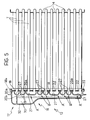
- the latter has two series of through-holes 23 and 25 respectively, arranged on opposite sides of the portion 20b of the baffle 20, as well as a plurality of elongate recessed portions 27 with substantially channel-shaped cross-sections arranged in correspondence with adjacent pairs of tubes T in an arrangement which, as shown clearly in Figures 2 and 3, forces the liquid circulating in the tubes in the central plane of the matrix 10a to be conveyed either into other tubes in the central plane (the recesses indicated A in Figures 3 and 5) or into tubes in planes parallel to the central plane of the matrix (the recesses indicated B in Figures 3 and 5).
- the portion 20b of the baffle 20 has a free edge E which is connected (by pressure or by ultrasonic welding), during the assembly of the exchanger, to the corresponding edge E′ of a central baffle plate 30 formed on the base wall 32 of the cover 16 of the header 12 ( Figure 8).
- edge E of the portion 20b of the baffle 20 is V-shaped and corresponds in shape to a V-shaped recess formed in the edge E' of the baffle plate 30.
- the edge of the metal tube plate 18, indicated 18b is folded over a shaped edge 16c of the cover 16 with the interpositon of the edge 22b of the flat gasket 22.
- the latter is therefore used both to effect a seal between the cover 16 and the tube plate 18 and to effect a seal between the baffle 20 and the tube plate 18 in order to prevent the leakage of liquid between its various passages tube-side ( Figures 2 and 8).
- the fluid admitted by the connector 16a is forced by the portion 20b of the baffle 20 to pass through the first series of holes 23 and to flow along a first set of U-shaped tubes of the matrix 10a and back again.
- the liquid is returned thereto by the U-shaped recesses 27 and thus passes twice more through the matrix of finned tubes 10a.
- the liquid returning from its fourth and last passage through the matrix of tubes flows through the second series of holes 25 and is conveyed to the outlet connector 16b of the exchanger 10 ( Figure 2).
Landscapes
- Engineering & Computer Science (AREA)
- Physics & Mathematics (AREA)
- Thermal Sciences (AREA)
- Mechanical Engineering (AREA)
- General Engineering & Computer Science (AREA)
- Heat-Exchange Devices With Radiators And Conduit Assemblies (AREA)
- Air-Conditioning For Vehicles (AREA)
- Laminated Bodies (AREA)
Applications Claiming Priority (2)
| Application Number | Priority Date | Filing Date | Title |
|---|---|---|---|
| IT06785689A IT1237601B (it) | 1989-10-06 | 1989-10-06 | Scambiatore di calore a tubi d'acqua per impianti di climatizzazione di autoveicoli con collettore dotato di setto partitore di flusso. |
| IT6785689 | 1989-10-06 |
Publications (2)
| Publication Number | Publication Date |
|---|---|
| EP0421955A1 EP0421955A1 (en) | 1991-04-10 |
| EP0421955B1 true EP0421955B1 (en) | 1994-03-16 |
Family
ID=11305827
Family Applications (1)
| Application Number | Title | Priority Date | Filing Date |
|---|---|---|---|
| EP90830429A Expired - Lifetime EP0421955B1 (en) | 1989-10-06 | 1990-10-02 | Water-tube heat exchanger for a motor vehicle air-conditioning system, having a header with a baffle for dividing the flow |
Country Status (4)
| Country | Link |
|---|---|
| EP (1) | EP0421955B1 (it) |
| DE (1) | DE69007410T2 (it) |
| ES (1) | ES2050415T3 (it) |
| IT (1) | IT1237601B (it) |
Families Citing this family (4)
| Publication number | Priority date | Publication date | Assignee | Title |
|---|---|---|---|---|
| DE9107174U1 (de) * | 1991-06-11 | 1991-07-25 | Behr GmbH & Co, 7000 Stuttgart | Wasserkasten für einen Wärmetauscher |
| US5205347A (en) * | 1992-03-31 | 1993-04-27 | Modine Manufacturing Co. | High efficiency evaporator |
| EP0978702A1 (en) * | 1998-07-09 | 2000-02-09 | Sierra S.p.A. | Device for a heat-exchange terminal with a finned assembly |
| ITUD20110191A1 (it) * | 2011-11-25 | 2013-05-26 | Bruno Pilosio | Scambiatore di calore ad alette perfezionato e procedimento di produzione |
Family Cites Families (7)
| Publication number | Priority date | Publication date | Assignee | Title |
|---|---|---|---|---|
| US3782454A (en) * | 1972-02-24 | 1974-01-01 | Modine Mfg Co | Heat exchanger |
| JPS5264733A (en) * | 1975-11-21 | 1977-05-28 | Hitachi Ltd | Evaporator |
| FR2390692A1 (fr) * | 1977-05-13 | 1978-12-08 | Mangeol Charles | Echangeur de chaleur, generateur d'eau chaude |
| ES512122A0 (es) * | 1981-07-08 | 1983-02-16 | Sueddeutsche Kuehler Behr | "perfeccionamientos en los evaporadores". |
| FR2573190A1 (fr) * | 1984-11-12 | 1986-05-16 | Chausson Usines Sa | Evaporateur multitubulaire a boite distributrice rapportee |
| DE3733866A1 (de) * | 1987-10-07 | 1989-04-27 | Sueddeutsche Kuehler Behr | Waermetauscher |
| EP0328414A3 (en) * | 1988-02-12 | 1989-09-27 | Acr Heat Transfer Manufacturing Limited | Heat exchanger |
-
1989
- 1989-10-06 IT IT06785689A patent/IT1237601B/it active IP Right Grant
-
1990
- 1990-10-02 ES ES90830429T patent/ES2050415T3/es not_active Expired - Lifetime
- 1990-10-02 EP EP90830429A patent/EP0421955B1/en not_active Expired - Lifetime
- 1990-10-02 DE DE69007410T patent/DE69007410T2/de not_active Expired - Fee Related
Also Published As
| Publication number | Publication date |
|---|---|
| IT1237601B (it) | 1993-06-08 |
| ES2050415T3 (es) | 1994-05-16 |
| IT8967856A1 (it) | 1991-04-06 |
| DE69007410T2 (de) | 1994-07-07 |
| DE69007410D1 (de) | 1994-04-21 |
| EP0421955A1 (en) | 1991-04-10 |
| IT8967856A0 (it) | 1989-10-06 |
Similar Documents
| Publication | Publication Date | Title |
|---|---|---|
| US5062476A (en) | Heat exchanger with an extruded tank | |
| EP0450619B1 (en) | Heat exchanger tank partition device | |
| EP0588117A1 (en) | Stacked heat exchanger | |
| US5450896A (en) | Two-piece header | |
| EP0683373B1 (en) | Heat exchanger and method of making same | |
| EP0661508B1 (en) | Layered heat exchangers | |
| US5236336A (en) | Heat exchanger | |
| EP0660063B1 (en) | Heat exchanger | |
| US5195581A (en) | Snap on radiator tank | |
| US5209292A (en) | Condenser header and tank assembly with interference fit baffle | |
| EP0745822B1 (en) | Heat exchanger with divided header tank | |
| EP0151879A2 (en) | Heat exchanger | |
| US5507338A (en) | Tab for an automotive heat exchanger | |
| US5190100A (en) | Condenser for use in a car cooling system | |
| US5855240A (en) | Automotive heat exchanger | |
| EP0172659A1 (en) | Single inlet/outlet-tank U-shaped tube heat exchanger | |
| JPH0463319B2 (it) | ||
| CN110530190A (zh) | 集管箱及换热器 | |
| EP0421955A1 (en) | Water-tube heat exchanger for a motor vehicle air-conditioning system, having a header with a baffle for dividing the flow | |
| EP0658734A2 (en) | A heat exchanger for an automotive vehicle | |
| US5238059A (en) | Heat exchanger header with parallel edges | |
| AU747879B2 (en) | Modular heat exchanger and method of making | |
| EP0679851A1 (en) | Laminated heat exchanger with a single tank structure | |
| EP0328414A3 (en) | Heat exchanger | |
| EP0805330A2 (en) | Heat exchanger enabling leak test of chambers in tank separated by single partition |
Legal Events
| Date | Code | Title | Description |
|---|---|---|---|
| PUAI | Public reference made under article 153(3) epc to a published international application that has entered the european phase |
Free format text: ORIGINAL CODE: 0009012 |
|
| AK | Designated contracting states |
Kind code of ref document: A1 Designated state(s): DE ES FR GB SE |
|
| 17P | Request for examination filed |
Effective date: 19911001 |
|
| 17Q | First examination report despatched |
Effective date: 19920724 |
|
| GRAA | (expected) grant |
Free format text: ORIGINAL CODE: 0009210 |
|
| AK | Designated contracting states |
Kind code of ref document: B1 Designated state(s): DE ES FR GB SE |
|
| REF | Corresponds to: |
Ref document number: 69007410 Country of ref document: DE Date of ref document: 19940421 |
|
| REG | Reference to a national code |
Ref country code: ES Ref legal event code: FG2A Ref document number: 2050415 Country of ref document: ES Kind code of ref document: T3 |
|
| ET | Fr: translation filed | ||
| PLBE | No opposition filed within time limit |
Free format text: ORIGINAL CODE: 0009261 |
|
| STAA | Information on the status of an ep patent application or granted ep patent |
Free format text: STATUS: NO OPPOSITION FILED WITHIN TIME LIMIT |
|
| EAL | Se: european patent in force in sweden |
Ref document number: 90830429.8 |
|
| 26N | No opposition filed | ||
| REG | Reference to a national code |
Ref country code: GB Ref legal event code: IF02 |
|
| PGFP | Annual fee paid to national office [announced via postgrant information from national office to epo] |
Ref country code: DE Payment date: 20020918 Year of fee payment: 13 |
|
| PGFP | Annual fee paid to national office [announced via postgrant information from national office to epo] |
Ref country code: SE Payment date: 20020925 Year of fee payment: 13 |
|
| PGFP | Annual fee paid to national office [announced via postgrant information from national office to epo] |
Ref country code: GB Payment date: 20021002 Year of fee payment: 13 |
|
| PGFP | Annual fee paid to national office [announced via postgrant information from national office to epo] |
Ref country code: ES Payment date: 20021010 Year of fee payment: 13 |
|
| PGFP | Annual fee paid to national office [announced via postgrant information from national office to epo] |
Ref country code: FR Payment date: 20021011 Year of fee payment: 13 |
|
| PG25 | Lapsed in a contracting state [announced via postgrant information from national office to epo] |
Ref country code: GB Free format text: LAPSE BECAUSE OF NON-PAYMENT OF DUE FEES Effective date: 20031002 |
|
| PG25 | Lapsed in a contracting state [announced via postgrant information from national office to epo] |
Ref country code: SE Free format text: LAPSE BECAUSE OF NON-PAYMENT OF DUE FEES Effective date: 20031003 Ref country code: ES Free format text: LAPSE BECAUSE OF NON-PAYMENT OF DUE FEES Effective date: 20031003 |
|
| PG25 | Lapsed in a contracting state [announced via postgrant information from national office to epo] |
Ref country code: DE Free format text: LAPSE BECAUSE OF NON-PAYMENT OF DUE FEES Effective date: 20040501 |
|
| GBPC | Gb: european patent ceased through non-payment of renewal fee |
Effective date: 20031002 |
|
| EUG | Se: european patent has lapsed | ||
| PG25 | Lapsed in a contracting state [announced via postgrant information from national office to epo] |
Ref country code: FR Free format text: LAPSE BECAUSE OF NON-PAYMENT OF DUE FEES Effective date: 20040630 |
|
| REG | Reference to a national code |
Ref country code: FR Ref legal event code: ST |
|
| REG | Reference to a national code |
Ref country code: ES Ref legal event code: FD2A Effective date: 20031003 |