EP0421970A1 - Verfahren und Vorrichtung zum Sammeln von Staub und Abfall in Webmaschinen - Google Patents
Verfahren und Vorrichtung zum Sammeln von Staub und Abfall in Webmaschinen Download PDFInfo
- Publication number
- EP0421970A1 EP0421970A1 EP90870155A EP90870155A EP0421970A1 EP 0421970 A1 EP0421970 A1 EP 0421970A1 EP 90870155 A EP90870155 A EP 90870155A EP 90870155 A EP90870155 A EP 90870155A EP 0421970 A1 EP0421970 A1 EP 0421970A1
- Authority
- EP
- European Patent Office
- Prior art keywords
- waste
- dust
- ribbon
- spool
- wound
- Prior art date
- Legal status (The legal status is an assumption and is not a legal conclusion. Google has not performed a legal analysis and makes no representation as to the accuracy of the status listed.)
- Withdrawn
Links
- 239000002699 waste material Substances 0.000 title claims abstract description 110
- 239000000428 dust Substances 0.000 title claims abstract description 55
- 238000000034 method Methods 0.000 title claims abstract description 26
- 238000009941 weaving Methods 0.000 title claims abstract description 24
- 238000004804 winding Methods 0.000 claims description 5
- 230000008878 coupling Effects 0.000 claims description 2
- 238000010168 coupling process Methods 0.000 claims description 2
- 238000005859 coupling reaction Methods 0.000 claims description 2
- 239000004744 fabric Substances 0.000 description 2
- 238000009434 installation Methods 0.000 description 2
- 235000014676 Phragmites communis Nutrition 0.000 description 1
- 238000007664 blowing Methods 0.000 description 1
- 230000006835 compression Effects 0.000 description 1
- 238000007906 compression Methods 0.000 description 1
- 230000000694 effects Effects 0.000 description 1
- 238000007667 floating Methods 0.000 description 1
Images
Classifications
-
- D—TEXTILES; PAPER
- D03—WEAVING
- D03J—AUXILIARY WEAVING APPARATUS; WEAVERS' TOOLS; SHUTTLES
- D03J1/00—Auxiliary apparatus combined with or associated with looms
- D03J1/002—Climatic conditioning or removing lint or dust
Definitions
- This invention concerns a method and device for collecting dust and waste in weaving machines.
- a solution to collect larger amounts of dust in a container is known from the US 4.532.860, whereby the container is provided with a floating lid which compresses the dust collected in the container. Although such a container needs to be emptied less frequently, the disadvantage remains that the use of a container is necessary. Further, the compression of the dust collected in the container is still relatively small.
- the present invention concerns a method and a device for collecting dust and waste in weaving machines, in particular in weaving machines whereby a waste ribbon is formed which is wound around a waste spool, which do not have the above-mentioned disadvantages, in other words whereby the collection of the dust does not require a traditional container and whereby the dust and possible waste are collected in a very compact manner.
- the invention concerns a method for collecting dust and waste in weaving machines, in particular in a weaving process of the type whereby a waste ribbon is formed which is wound round a waste spool, characterized in that the method consists essentially of that at least a part of the dust and/or waste formed during the weaving process is wound between the waste ribbon.
- the dust and similar are sucked up at well-defined places in the weaving machine and subsequently brought into contact with the waste ribbon, for example by blowing the dust on said waste ribbon, such that it is carried along by the waste ribbon and wound between the waste ribbon. Given the tension with which the waste ribbon is wound around the waste spool, the dust is compressed optimally.
- a waste spool is used which is provided with an almost closed housing, such that the dust which does not stick to the waste ribbon at once, is piled up at the bottom of the space enclosed by the housing until it makes contact with the wound-up waste ribbon and is thus wound up along with the waste ribbon and compressed.
- the present invention also concerns a device to realize the method, of which the structure is explained in the detailed description.
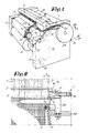
- Fig. 1 shows a weaving machine which is equipped with a device 1 according to the invention.
- the generally known parts, also indicated in fig. 1, are the reed 2, the warp threads 3, the shed 4, the cloth formed 5 and the cloth roll 6.
- a number of leno threads 7 may be provided next to the traditional warp threads 3, with the aim to hold the weft threads 8, after they have been inserted into the shed 4 at their ends 9.
- the leno threads 7 are situated at a well-defined distance D from the warp 3, such that the weft threads 8 between the normal warp threads 3 and the leno threads 7 can all be cut at the same length by means of a waste cutter 10.
- Fig. 1 also shows a number of means, preferably consisting of a number of suction nozzles, to pick up dust and possible waste.
- fig. 1 shows a suction nozzle 14 which is placed next to the end of the shed 4, as well as a suction nozzle 15 which is situated underneath the weaving machine.
- the suction can be based on various principles.
- suction in suction nozzle 14 is obtained by the suction effect of an air current which ends over an angle in the suction nozzle 14 via a supply channel 17 connected to a compressed air source 16. It should be stated that the suction nozzle 14 collects the dust which is transported along through the shed 4, and is also meant to collect waste, such as faulty weft threads which must be removed from the shed.
- suction nozzle 15 is, as schematically represented in fig. 1, connected to a traditional suction installation 18.
- the dust sucked up at the suction nozzles 14 and 15 is led through a tube to a container, where the dust and possible waste are caught, this having the disadvantages as described in the introduction.
- the present invention offers a solution to these disadvantages in that the dust and waste sucked up at the suction nozzles, in this case the suction nozzles 14 and 15, are wound up between the waste ribbon 11.
- the device 1 according to the invention has one or preferably more flexible tubes 19 to lead the dust or waste from the suction nozzles 14 and 15 to the waste spool 13, as well as means, such as a blow opening 20 at the end of the above-mentioned tube 19 to bring the dust into contact with the waste ribbon 11 at the height of the waste spool 13, such that the dust is developed and compressed between the waste ribbon.
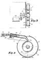
- a housing or lid 21 may be provided around the waste spool 13, such that any dust 22 whirling around between the flanges 23 of the waste spool 13 remains present.
- the dust 22 piles up at the bottom of the space formed, until is comes into contact with the wound-up waste ribbon 11, such that it is carried along and eventually is wound up between the waste ribbon.
- the above-mentioned blow opening 20 is preferably situated above the waste spool 13 and is directed towards the waste ribbon 11.
- the tube 19 between the suction nozzle 14 and the waste spool 13 is preferably telescopic, for example because the flexible part 24 of said tube can be moved freely in a tube-shaped part 25.
- the tube-shaped part is hung up at its end which is situated opposite the blow opening 20 to a hinge point 26, such that this part 25 continuously rests by its own weight on the wound-up waste ribbon 11 near the blow opening 20, such that the blow opening 20 is permanently presented against said waste ribbon, regardless of the winding diameter.
- the above-mentioned telescopic operation allows the suction nozzle 14 to be adjusted in function of the weaving width desired, for example because the screws 27 shown in fig. 2 are loosened, such that the support 28 with the suction nozzle 14 attached to it may be moved in a slot 29.
- the means to drive the waste spool 13 may be chosen arbitrarily. For the sake of completeness, an example is shown in fig. 3, whereby the drive is done by a motor 30 and a slip coupling 31, whereby the motor turns faster than is required for winding the waste ribbon 11, such that a permanent traction is exerted on the waste ribbon 11.
- the dust may be blown underneath the waste ribbon 11, in particular between the part running on the waste spool and the part already wound up.
Landscapes
- Engineering & Computer Science (AREA)
- Textile Engineering (AREA)
- Auxiliary Weaving Apparatuses, Weavers' Tools, And Shuttles (AREA)
Applications Claiming Priority (2)
| Application Number | Priority Date | Filing Date | Title |
|---|---|---|---|
| BE8901057A BE1003533A3 (nl) | 1989-10-04 | 1989-10-04 | Werkwijze en inrichting voor het verzamelen van stof en afval bij weefmachines. |
| BE8901057 | 1989-10-04 |
Publications (1)
| Publication Number | Publication Date |
|---|---|
| EP0421970A1 true EP0421970A1 (de) | 1991-04-10 |
Family
ID=3884330
Family Applications (1)
| Application Number | Title | Priority Date | Filing Date |
|---|---|---|---|
| EP90870155A Withdrawn EP0421970A1 (de) | 1989-10-04 | 1990-09-19 | Verfahren und Vorrichtung zum Sammeln von Staub und Abfall in Webmaschinen |
Country Status (3)
| Country | Link |
|---|---|
| US (1) | US5040570A (de) |
| EP (1) | EP0421970A1 (de) |
| BE (1) | BE1003533A3 (de) |
Families Citing this family (6)
| Publication number | Priority date | Publication date | Assignee | Title |
|---|---|---|---|---|
| DE19545839C1 (de) * | 1995-12-08 | 1996-08-29 | Dornier Gmbh Lindauer | Verfahren und Webmaschine zur Handhabung eines Schußfadens |
| CN102330261A (zh) * | 2011-07-21 | 2012-01-25 | 吴江市锦邦纺织品有限公司 | 织布机废边收集装置 |
| CN102677372A (zh) * | 2012-05-22 | 2012-09-19 | 山东济宁如意毛纺织股份有限公司 | 一种剑杆织机吸风式废边纱的处理方法 |
| CN103789914A (zh) * | 2012-11-02 | 2014-05-14 | 吴江市嘉运纺织整理有限公司 | 一种织机除尘装置 |
| CN106592069B (zh) * | 2016-12-30 | 2018-07-06 | 吴江市兴业纺织有限公司 | 一种喷气织机 |
| CN115287793B (zh) * | 2022-07-29 | 2024-05-10 | 佛山市昶瑞纺织有限公司 | 一种自动化棉纱纺织机 |
Citations (5)
| Publication number | Priority date | Publication date | Assignee | Title |
|---|---|---|---|---|
| DE2063521A1 (de) * | 1969-12-24 | 1971-07-01 | Yoshida Kogyo K K ,Tokio | Pneumatische Absaugvorrichtung fur Textilmaschinen |
| GB1419232A (en) * | 1974-02-18 | 1975-12-24 | Elitex Zavody Textilniho | Method and device for collecting a severed leno selvedge in looms device for use in handling loads such as sheets |
| US4532860A (en) * | 1983-01-21 | 1985-08-06 | Sulzer Brothers Limited | Apparatus for collecting waste from a textile machine |
| FR2576610A1 (fr) * | 1985-01-28 | 1986-08-01 | Alsacienne Constr Mat Tex | Procede et dispositif pour evacuer les meches de dechets sur un metier a tisser |
| EP0192014A1 (de) * | 1985-02-20 | 1986-08-27 | GebràDer Sulzer Aktiengesellschaft | Reinigungsgerät für Textilmaschinen |
Family Cites Families (5)
| Publication number | Priority date | Publication date | Assignee | Title |
|---|---|---|---|---|
| JPS52155260A (en) * | 1976-06-17 | 1977-12-23 | Nissan Motor | Device for removing fly waste in fluiddjet loom |
| CH624438A5 (de) * | 1977-11-07 | 1981-07-31 | Sulzer Ag | |
| JPS56145069A (en) * | 1980-04-12 | 1981-11-11 | Nissan Motor Co Ltd | Taking-up apparatus for end catching yarn in fragment weaving machine |
| US4453572A (en) * | 1982-07-26 | 1984-06-12 | Burlington Industries, Inc. | Method and apparatus for waste selvage removal |
| US4691743A (en) * | 1985-01-28 | 1987-09-08 | Societe Alsacienne De Construction De Material Textile | Method and device for removal of waste slivers in a weaving loom |
-
1989
- 1989-10-04 BE BE8901057A patent/BE1003533A3/nl not_active IP Right Cessation
-
1990
- 1990-09-19 EP EP90870155A patent/EP0421970A1/de not_active Withdrawn
- 1990-09-28 US US07/589,275 patent/US5040570A/en not_active Expired - Fee Related
Patent Citations (5)
| Publication number | Priority date | Publication date | Assignee | Title |
|---|---|---|---|---|
| DE2063521A1 (de) * | 1969-12-24 | 1971-07-01 | Yoshida Kogyo K K ,Tokio | Pneumatische Absaugvorrichtung fur Textilmaschinen |
| GB1419232A (en) * | 1974-02-18 | 1975-12-24 | Elitex Zavody Textilniho | Method and device for collecting a severed leno selvedge in looms device for use in handling loads such as sheets |
| US4532860A (en) * | 1983-01-21 | 1985-08-06 | Sulzer Brothers Limited | Apparatus for collecting waste from a textile machine |
| FR2576610A1 (fr) * | 1985-01-28 | 1986-08-01 | Alsacienne Constr Mat Tex | Procede et dispositif pour evacuer les meches de dechets sur un metier a tisser |
| EP0192014A1 (de) * | 1985-02-20 | 1986-08-27 | GebràDer Sulzer Aktiengesellschaft | Reinigungsgerät für Textilmaschinen |
Also Published As
| Publication number | Publication date |
|---|---|
| BE1003533A3 (nl) | 1992-04-14 |
| US5040570A (en) | 1991-08-20 |
Similar Documents
| Publication | Publication Date | Title |
|---|---|---|
| US4571931A (en) | Spinning and winding plant | |
| EP0421970A1 (de) | Verfahren und Vorrichtung zum Sammeln von Staub und Abfall in Webmaschinen | |
| WO1982001115A1 (en) | Device in lawn mowers,leaf-collecting machines and the like | |
| JPS58157678A (ja) | 自動ワインダ−における管糸搬送システム | |
| US4453572A (en) | Method and apparatus for waste selvage removal | |
| US4592393A (en) | Weft thread preparation device | |
| EP0306080A1 (de) | Leisteneinzugsvorrichtung für Webmaschinen | |
| CA1333986C (en) | Automatic cop exchanging apparatus for shuttle loom | |
| KR920001806B1 (ko) | 정방관사의 구사 인출장치 | |
| US6401314B1 (en) | Method and a device for thread division on a sectional warping machine | |
| JPS6117926B2 (de) | ||
| EP0306079A1 (de) | Vorrichtung zum Ausbessern eines Schussfadens an Webmaschinen | |
| EP0344848A1 (de) | Verfahren zum Einfädeln der Düsen mit einer richtigen Schlussfadenlänge und Webmaschine, die nach diesem Verfahren arbeitet | |
| ITMI960508A1 (it) | Dispositivo di ricerca ddell'estremita' del filo su spole | |
| US4315529A (en) | Weaving machine having means for ventilating a weft supply means | |
| US5046532A (en) | Improper weft removing device for air jet loom | |
| EP0492461A1 (de) | Verfahren zum Entfernen eines fehlerhaften Schussfadens | |
| US2834090A (en) | Suction type bobbin stripper | |
| US3523651A (en) | Apparatus for catching an end of a feed yarn in a pirn winder and the like | |
| IE44332L (en) | Weaving loom | |
| JPS58152767A (ja) | 自動ワインダ−における管糸搬送システム | |
| CN116103818A (zh) | 一种扁丝引纬系统 | |
| US6105337A (en) | System for making waterproof bags by lining bag shell with tubular film | |
| US2453603A (en) | Method and apparatus for stripping yarn packages | |
| EP1639167B1 (de) | Vorrichtung zum zusammenpressen und entladen von schussfadenabvall in ein gerät zum entfernen von schussfadenabfall in webmaschinen |
Legal Events
| Date | Code | Title | Description |
|---|---|---|---|
| PUAI | Public reference made under article 153(3) epc to a published international application that has entered the european phase |
Free format text: ORIGINAL CODE: 0009012 |
|
| AK | Designated contracting states |
Kind code of ref document: A1 Designated state(s): CH DE FR GB IT LI |
|
| 17P | Request for examination filed |
Effective date: 19910528 |
|
| 17Q | First examination report despatched |
Effective date: 19930623 |
|
| STAA | Information on the status of an ep patent application or granted ep patent |
Free format text: STATUS: THE APPLICATION IS DEEMED TO BE WITHDRAWN |
|
| 18D | Application deemed to be withdrawn |
Effective date: 19940124 |