EP0421982B1 - System mit rotierenden paletten - Google Patents
System mit rotierenden paletten Download PDFInfo
- Publication number
- EP0421982B1 EP0421982B1 EP88901415A EP88901415A EP0421982B1 EP 0421982 B1 EP0421982 B1 EP 0421982B1 EP 88901415 A EP88901415 A EP 88901415A EP 88901415 A EP88901415 A EP 88901415A EP 0421982 B1 EP0421982 B1 EP 0421982B1
- Authority
- EP
- European Patent Office
- Prior art keywords
- wedge
- piece
- machined
- pieces
- rotary
- Prior art date
- Legal status (The legal status is an assumption and is not a legal conclusion. Google has not performed a legal analysis and makes no representation as to the accuracy of the status listed.)
- Expired - Lifetime
Links
Images


Classifications
-
- B—PERFORMING OPERATIONS; TRANSPORTING
- B25—HAND TOOLS; PORTABLE POWER-DRIVEN TOOLS; MANIPULATORS
- B25B—TOOLS OR BENCH DEVICES NOT OTHERWISE PROVIDED FOR, FOR FASTENING, CONNECTING, DISENGAGING, OR HOLDING
- B25B5/00—Clamps
- B25B5/06—Arrangements for positively actuating jaws
- B25B5/10—Arrangements for positively actuating jaws using screws
-
- B—PERFORMING OPERATIONS; TRANSPORTING
- B23—MACHINE TOOLS; METAL-WORKING NOT OTHERWISE PROVIDED FOR
- B23Q—DETAILS, COMPONENTS, OR ACCESSORIES FOR MACHINE TOOLS, e.g. ARRANGEMENTS FOR COPYING OR CONTROLLING; MACHINE TOOLS IN GENERAL CHARACTERISED BY THE CONSTRUCTION OF PARTICULAR DETAILS OR COMPONENTS; COMBINATIONS OR ASSOCIATIONS OF METAL-WORKING MACHINES, NOT DIRECTED TO A PARTICULAR RESULT
- B23Q1/00—Members which are comprised in the general build-up of a form of machine, particularly relatively large fixed members
- B23Q1/03—Stationary work or tool supports
- B23Q1/032—Stationary work or tool supports characterised by properties of the support surface
-
- B—PERFORMING OPERATIONS; TRANSPORTING
- B23—MACHINE TOOLS; METAL-WORKING NOT OTHERWISE PROVIDED FOR
- B23Q—DETAILS, COMPONENTS, OR ACCESSORIES FOR MACHINE TOOLS, e.g. ARRANGEMENTS FOR COPYING OR CONTROLLING; MACHINE TOOLS IN GENERAL CHARACTERISED BY THE CONSTRUCTION OF PARTICULAR DETAILS OR COMPONENTS; COMBINATIONS OR ASSOCIATIONS OF METAL-WORKING MACHINES, NOT DIRECTED TO A PARTICULAR RESULT
- B23Q3/00—Devices holding, supporting, or positioning work or tools, of a kind normally removable from the machine
- B23Q3/02—Devices holding, supporting, or positioning work or tools, of a kind normally removable from the machine for mounting on a work-table, tool-slide, or analogous part
- B23Q3/06—Work-clamping means
- B23Q3/062—Work-clamping means adapted for holding workpieces having a special form or being made from a special material
-
- B—PERFORMING OPERATIONS; TRANSPORTING
- B25—HAND TOOLS; PORTABLE POWER-DRIVEN TOOLS; MANIPULATORS
- B25B—TOOLS OR BENCH DEVICES NOT OTHERWISE PROVIDED FOR, FOR FASTENING, CONNECTING, DISENGAGING, OR HOLDING
- B25B1/00—Vices
- B25B1/06—Arrangements for positively actuating jaws
- B25B1/10—Arrangements for positively actuating jaws using screws
-
- Y—GENERAL TAGGING OF NEW TECHNOLOGICAL DEVELOPMENTS; GENERAL TAGGING OF CROSS-SECTIONAL TECHNOLOGIES SPANNING OVER SEVERAL SECTIONS OF THE IPC; TECHNICAL SUBJECTS COVERED BY FORMER USPC CROSS-REFERENCE ART COLLECTIONS [XRACs] AND DIGESTS
- Y10—TECHNICAL SUBJECTS COVERED BY FORMER USPC
- Y10S—TECHNICAL SUBJECTS COVERED BY FORMER USPC CROSS-REFERENCE ART COLLECTIONS [XRACs] AND DIGESTS
- Y10S409/00—Gear cutting, milling, or planing
- Y10S409/903—Work holder
-
- Y—GENERAL TAGGING OF NEW TECHNOLOGICAL DEVELOPMENTS; GENERAL TAGGING OF CROSS-SECTIONAL TECHNOLOGIES SPANNING OVER SEVERAL SECTIONS OF THE IPC; TECHNICAL SUBJECTS COVERED BY FORMER USPC CROSS-REFERENCE ART COLLECTIONS [XRACs] AND DIGESTS
- Y10—TECHNICAL SUBJECTS COVERED BY FORMER USPC
- Y10T—TECHNICAL SUBJECTS COVERED BY FORMER US CLASSIFICATION
- Y10T409/00—Gear cutting, milling, or planing
- Y10T409/30—Milling
- Y10T409/306664—Milling including means to infeed rotary cutter toward work
- Y10T409/307448—Milling including means to infeed rotary cutter toward work with work holder
- Y10T409/307504—Indexable
-
- Y—GENERAL TAGGING OF NEW TECHNOLOGICAL DEVELOPMENTS; GENERAL TAGGING OF CROSS-SECTIONAL TECHNOLOGIES SPANNING OVER SEVERAL SECTIONS OF THE IPC; TECHNICAL SUBJECTS COVERED BY FORMER USPC CROSS-REFERENCE ART COLLECTIONS [XRACs] AND DIGESTS
- Y10—TECHNICAL SUBJECTS COVERED BY FORMER USPC
- Y10T—TECHNICAL SUBJECTS COVERED BY FORMER US CLASSIFICATION
- Y10T409/00—Gear cutting, milling, or planing
- Y10T409/30—Milling
- Y10T409/30868—Work support
- Y10T409/308792—Indexable
-
- Y—GENERAL TAGGING OF NEW TECHNOLOGICAL DEVELOPMENTS; GENERAL TAGGING OF CROSS-SECTIONAL TECHNOLOGIES SPANNING OVER SEVERAL SECTIONS OF THE IPC; TECHNICAL SUBJECTS COVERED BY FORMER USPC CROSS-REFERENCE ART COLLECTIONS [XRACs] AND DIGESTS
- Y10—TECHNICAL SUBJECTS COVERED BY FORMER USPC
- Y10T—TECHNICAL SUBJECTS COVERED BY FORMER US CLASSIFICATION
- Y10T409/00—Gear cutting, milling, or planing
- Y10T409/30—Milling
- Y10T409/30868—Work support
- Y10T409/309016—Work support with work holder or guide
Definitions
- the present invention concerns a rotary-pallet system, in particular for multi-directional machining of pieces to be machined according to the preamble of claim 1.
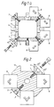
- the fastening member in accordance with the invention comprises a body 2, in which, at the end A of the axial centre line of the body, there is an attachment to an indexed table or to the index head (not shown in the Figure) of the machine. At the opposite end B of the body, there is a corresponding centre for the support bearing (Fig. 3b).
- the body 2 of the rotary pallet has four sides.
- the edges of the body are chamfered, and into them grooves 7 parallel to the axis of the body have been formed, the bottoms of the said grooves forming an angle of 135° with the sides of the body.
- the bottom of the grooves there is a line of holes 6 with inside threading, which said holes are directed towards the central axis of the body.
- wedge pieces 3 have been attached by means of screws 1, on which said wedge pieces the face facing the groove 7 and the opposite face are parallel to the bottom of the groove 7. Thereat, the screw 1 is at an angle of 45° relative the sides of the body 2.
- the sides of the wedge pieces are at a right angle to the side faces of the body 2.
- Each groove has either one oblong wedge piece or several wedge pieces in a line.
- the wedge pieces are provided with return springs (not shown in the Figures), which attempt to push the wedge pieces apart from the body 2.
- middle support guides 4 At the middle between the four guide sides of the body there are likewise axial grooves 11, in which there are holes 12 with inside threading for the fastening of the middle support guides 4 by means of screws.
- the sides of the middle support guides form a right angle with the guide sides of the body. It is possible to use middle supports 4 of different widths, depending on the size of the pieces to be machined.
- the pieces 8 to be machined are rectangular prisms, and they are fixed against the guide face of the body 2 and against the middle support guide 4 by tightening the wedge pieces 3 by means of screws 1 towards the body 2. In this way it is possible to set the distance between the middle support guides 4 and one side of the wedge piece 3 in accordance with the pieces 8 to be attached.
- the arrows drawn on the pieces to be machined denote the two principal machining directions of the pieces. It is seen that, when the body 2 is rotated around its central axis four times over 90°, all the pieces 8 attached to it in eight lines can be machined from two directions by using two machining directions.
- Fig. 1b shows one corner of the body 2 shown in Fig. 1a, and a wedge piece 3 to be fitted in it and a screw 1.
- Fig. 1c shows an alternative in which a flat chamfer parallel to the bottom of the wedge piece has been used instead of the groove 7 in the corner.
- the groove 7 has been formed by means of two surfaces parallel to the wedge surfaces of the wedge piece.
- the forms of the bottom surface of the wedge piece 3 and the surface of the body 2 facing the wedge piece are not important because usually there remains a gap between the surfaces. Important is only the fact that the wedge surfaces of the wedge piece and the guide surface of the body are formed according to the piece 8 to be machined.
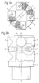
- Figures 3a and 3b show an embodiment to which cylindrical pieces 9 to be machined can be attached in four lines of two pieces so that one end of the cylinders is facing the central axis of the body and the axes of the cylinders are placed radially to the axis of the body.
- the body is provided with wings 13 acting as counter-faces, and the fastening takes place by means of two wedge pieces 3, which are pressed towards the body by means of screws 1.
- the wings 13 and the wedge pieces 3 are shaped in accordance with the cylinder faces of the pieces 9.
- Figures 4a and 4b show an embodiment in which the pieces 10 to be attached are also cylindrical, but the axes of the cylinders are parallel to the central axis of the body 2.
- the counter-faces on the body and the wedge pieces 3 are shaped accordingly, so that they become positioned against the cylinder faces.
- Fig. 4b the body has been rotated over 45° from the position shown in Fig. 4a. It is seen that, in addition to the three machining directions obtained from the rotations of 90°, two further machining directions are obtained.
- the curve radius of the cylinder faces on the wedge pieces 3 and on the body 2 is somewhat larger than the curve radius of the cylinders 10 to be machined, in which case the pieces become positioned stably in spite of minor dimensional deviations.
- the invention is not confined to the embodiments described above only, but it may show variation in many ways within the scope of the patent claims.
- the shape of the pieces 8, 9, 10 to be attached may also be different from a prism or cylinder, in which case the wedge piece 3 and the stationary counter-face on the body 2 and the counter-face on a separate support guide 4, if any, possibly attached to the body are shaped in accordance with the piece to be machined.
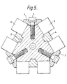
- the body 2 may also be, e.g., 3-sided (triangular section).
- 3-sided triangular section
- the body is possible to use wedge pieces whose sides form an angle of 120° with each other, in which case the screw 1 forms an angle of 30° with the sides of the body (Fig. 5).
Landscapes
- Engineering & Computer Science (AREA)
- Mechanical Engineering (AREA)
- Jigs For Machine Tools (AREA)
- Feeding Of Workpieces (AREA)
- Container Filling Or Packaging Operations (AREA)
- Warehouses Or Storage Devices (AREA)
- Pallets (AREA)
- Ultra Sonic Daignosis Equipment (AREA)
- Forging (AREA)
- Transition And Organic Metals Composition Catalysts For Addition Polymerization (AREA)
- Clamps And Clips (AREA)
Claims (10)
- System mit rotierenden Paletten, insbesondere für ein Bearbeiten von zu bearbeitenden Teilen (8, 9, 10) in mehreren Richtungen, umfassend einen Körper (2), dessen eines Ende (A) an einem Halter befestigt ist, wobei der Körper (2) um eine Längsachse (A-B) drehbar ist und wobei gegen seine in Längsrichtung verlaufenden Führungsflächen eines oder mehrere der zu bearbeitenden Teile (8, 9, 10) in Anlage bringbar ist, gekennzeichnet durch eines oder mehrere Keilstücke (3), welche an den Ecken der Führungsflächen am Körper (2) befestigt werden können, wobei die Keilfläche eines Keilstückes (3) gegen eine Seite der zu bearbeitenden Teile (8, 9, 10) gepreßt ist, während eine Gegenfläche (4, 13) gegen die gegenüberliegende Seite des zu bearbeitenden Teiles vorgesehen ist, wobei das Keilstück (3) an dem Körper mit Hilfe eines Befestigungsgliedes (1) festgelegt werden kann, welches unter einem Winkel derart orientiert ist, daß sich die Befestigungsbewegung des Keilstückes (3) zur selben Zeit sowohl an den Körper (2) als auch an das zu bearbeitende Teil (8, 9, 10) annähert.
- System mit rotierenden Paletten nach Anspruch 1, welches zwei oder mehrere Führungsflächen unfaßt, dadurch gekennzeichnet, daß das Keilstück (3) mit zwei Keilflächen ausgebildet ist und zwischen zwei Führungsflächen befestigt werden kann, welche nebeneinander derart angeordnet sind, daß eines oder mehrere der zu bearbeitenden Teile (8, 9, 10) gegen beide seiner Keilflächen eingepaßt werden kann (können).
- System mit rotierenden Paletten nach Anspruch 2, dadurch gekennzeichnet, daß die Befestigungsrichtung des Befestigungsgliedes (1) den Winkel zwischen zwei Führungsflächen auf seinen zwei Seiten in die Hälfte teilt.
- System mit rotierenden Paletten nach Anspruch 3, dessen Körper (2) mit vier Führungsflächen versehen ist, welche normal aufeinander stehen, und wobei gegen jede derselben ein oder mehrere der zu bearbeitenden Teile (8, 9, 10) angeordnet werden können, dadurch gekennzeichnet, daß die Befestigungsrichtung des Befestigungsgliedes (1) einen Winkel von 45° mit den an seinen beiden Seiten angeordneten Führungsflächen einschließt.
- System mit rotierenden Paletten nach Anspruch 4, dadurch gekennzeichnet, daß Keilstücke (3) an jeder Verbindung zwischen den vier Führungsflächen am Körper (2) einpaßbar sind.
- System mit rotierenden Paletten nach Anspruch 4, dadurch gekennzeichnet, daß Keilstücke (3) an zwei gegenüberliegenden Verbindungen zwischen den Führungsflächen am Körper (2) einpaßbar sind.
- System mit rotierenden Paletten nach einem der Ansprüche 1 bis 6, dadurch gekennzeichnet, daß die Gegenfläche (13) in einem Führungsanschlag ausgebildet ist, welcher von dem Körper (2) vorragt und einstückig mit diesem ausgebildet ist.
- System mit rotierenden Paletten nach einem der Ansprüche 1 bis 6, dadurch gekennzeichnet, daß die Gegenfläche (4) in einem Führungssupport ausgebildet ist, welcher lösbar am Körper festgelegt ist.
- System mit rotierenden Paletten nach einem der Ansprüche 1 bis 8, dadurch gekennzeichnet, daß das Befestigungsglied (1) eine mit einem Gewinde versehene Schraube oder eine Spindel ist, welche mit Hilfe eines Druckzylinders, einem Exzenter oder dgl. verschiebbar ist.
- System mit rotierenden Paletten nach einem der Ansprüche 1 bis 9, dadurch gekennzeichnet, daß zum Bearbeiten von Teilen (9, 10) unterschiedlicher Formen die Flächen des Körpers (2) und des Keilstückes (3), welche gegen das zu bearbeitende Teil angeordnet werden, entsprechend geformt sind.
Applications Claiming Priority (3)
| Application Number | Priority Date | Filing Date | Title |
|---|---|---|---|
| FI870290 | 1987-01-23 | ||
| FI870290A FI86815C (fi) | 1987-01-23 | 1987-01-23 | Rotationspalettsystem |
| PCT/FI1988/000006 WO1988005364A1 (en) | 1987-01-23 | 1988-01-22 | Rotary-pallet system |
Publications (2)
| Publication Number | Publication Date |
|---|---|
| EP0421982A1 EP0421982A1 (de) | 1991-04-17 |
| EP0421982B1 true EP0421982B1 (de) | 1994-09-07 |
Family
ID=8523822
Family Applications (1)
| Application Number | Title | Priority Date | Filing Date |
|---|---|---|---|
| EP88901415A Expired - Lifetime EP0421982B1 (de) | 1987-01-23 | 1988-01-22 | System mit rotierenden paletten |
Country Status (7)
| Country | Link |
|---|---|
| US (1) | US4921378A (de) |
| EP (1) | EP0421982B1 (de) |
| JP (1) | JP2525598B2 (de) |
| AT (1) | ATE111002T1 (de) |
| DE (1) | DE3851443T2 (de) |
| FI (1) | FI86815C (de) |
| WO (1) | WO1988005364A1 (de) |
Families Citing this family (37)
| Publication number | Priority date | Publication date | Assignee | Title |
|---|---|---|---|---|
| WO1991004127A1 (en) * | 1989-09-22 | 1991-04-04 | Renishaw Plc | Modular multi-fixturing system for a machine tool |
| JP2545291B2 (ja) * | 1990-01-20 | 1996-10-16 | 本田技研工業株式会社 | 傘歯車加工機の割出装置 |
| US4974304A (en) * | 1990-02-08 | 1990-12-04 | Sew Eurodrive, Inc. | Mounting apparatus for CNC machine |
| US5158487A (en) * | 1990-03-02 | 1992-10-27 | Proprietary Main, Inc. | Positioning fixture |
| DE4125961C2 (de) * | 1991-08-06 | 1995-04-06 | Giddings & Lewis Gmbh | Werkstückpalette als Werkstückträger für Transferstraßen |
| USD355200S (en) | 1992-02-06 | 1995-02-07 | Stevens Engineering, Inc. | Tooling support pedestal |
| IT1264251B1 (it) * | 1993-10-22 | 1996-09-23 | Paride Sacchi | Unita' per la lavorazione di pezzi in legno. |
| DE4341744C2 (de) * | 1993-12-08 | 2001-04-19 | Emil Stark | Tiefziehspanner für Spannvorrichtungen an Werkstückbearbeitungsmaschinen |
| US5501123A (en) * | 1994-09-02 | 1996-03-26 | Chick Machine Tool, Inc. | Indexing apparatus |
| US5535995A (en) * | 1994-09-02 | 1996-07-16 | Chick Machine Tool, Inc. | Apparatus for supporting multiple vise-like workholding devices |
| US5562277A (en) * | 1994-09-02 | 1996-10-08 | Chick Machine Tool, Inc. | Modular vise-like workholding system |
| US5716280A (en) * | 1995-09-29 | 1998-02-10 | Fairchild Holding Corp. | Method for forming a fluted fastener |
| US5658104A (en) * | 1996-02-02 | 1997-08-19 | Wong; Richard | Method and system for the manufacture of CO2 powered dragster |
| GB2331260A (en) * | 1997-11-12 | 1999-05-19 | Technologies Research Holding | Carrier for circular workpieces to be machined into sprocket wheels |
| US5871315A (en) * | 1997-12-22 | 1999-02-16 | Unova Ip Corp. | Tombstone fixture |
| JP3292832B2 (ja) * | 1998-02-16 | 2002-06-17 | 旭精機工業株式会社 | ワーク位置決め装置 |
| US6240807B1 (en) | 1999-03-03 | 2001-06-05 | Chick Workholding Solutions, Inc. | Indexing apparatus |
| US6237659B1 (en) * | 1999-03-08 | 2001-05-29 | David Francis | Rotatable work bench |
| US6273635B1 (en) * | 1999-05-10 | 2001-08-14 | Swanson Systems, Inc. | Mounting fixture for a modular assembly machine |
| EP1153703B1 (de) * | 1999-11-19 | 2004-01-21 | Makino Milling Machine Co. Ltd. | Numerisch gesteuerte werkzeugmaschine |
| DE10136202A1 (de) * | 2001-07-25 | 2003-02-06 | Braun Georg | Werkstückträger |
| US6719503B1 (en) | 2001-09-07 | 2004-04-13 | Unova Ip Corp | Tuned damped absorber support |
| US8636505B2 (en) * | 2005-06-01 | 2014-01-28 | Sirona Dental Systems Gmbh | Carrier for a fastening element to be fabricated and a method for production thereof, particularly as an orthodontic bracket |
| US7243407B2 (en) * | 2005-06-10 | 2007-07-17 | Marox Corporation | Modular turret-style base plate system for CNC machines |
| JP4837364B2 (ja) * | 2005-11-15 | 2011-12-14 | 株式会社テック・ヤスダ | 小物ワークの固定ジグ |
| US8573578B1 (en) | 2006-09-01 | 2013-11-05 | Chick Workholding Solutions, Inc. | Workholding apparatus |
| US8109494B1 (en) | 2006-09-01 | 2012-02-07 | Chick Workholding Solutions, Inc. | Workholding apparatus having a movable jaw member |
| US8454004B1 (en) | 2006-09-01 | 2013-06-04 | Chick Workholding Solutions, Inc. | Workholding apparatus having a movable jaw member |
| US9227303B1 (en) | 2006-09-01 | 2016-01-05 | Chick Workholding Solutions, Inc. | Workholding apparatus |
| US8336867B1 (en) | 2006-09-01 | 2012-12-25 | Chick Workholding Solutions, Inc. | Workholding apparatus having a detachable jaw plate |
| DE102010031117B4 (de) * | 2009-07-15 | 2022-01-20 | Fives Machining Systems, Inc. | Gedämpfter Drehgeber |
| US9010742B2 (en) | 2010-09-03 | 2015-04-21 | Richard Koczera | Part fixturing systems having expanding clamping devices |
| CN103182677B (zh) * | 2011-12-29 | 2015-04-22 | 财团法人金属工业研究发展中心 | 加工夹持工具 |
| US9182070B2 (en) | 2012-04-30 | 2015-11-10 | Threat Spectrum Inc. | Positioning device |
| CN103223603B (zh) * | 2013-04-19 | 2015-06-03 | 苏州弘远机械制造有限公司 | 一种主轴套精加工治具及加工工艺 |
| US9352451B1 (en) | 2013-05-02 | 2016-05-31 | Chick Workholding Solutions, Inc. | Workholding apparatus |
| CN104723151A (zh) * | 2015-03-31 | 2015-06-24 | 洛阳理工学院 | 一种用于车磨外圆柱面的装置 |
Family Cites Families (10)
| Publication number | Priority date | Publication date | Assignee | Title |
|---|---|---|---|---|
| US1352501A (en) * | 1917-01-02 | 1920-09-14 | United Shoe Machinery Corp | Heel-press |
| FR1220032A (fr) * | 1958-11-18 | 1960-05-20 | Blocs serre-plaques | |
| DE1502018B2 (de) * | 1965-01-13 | 1972-06-08 | Werkzeugmaschinen-Fabrik Gildemeister & Co Ag, 4800 Bielefeld | Werkstueck-spanntrommel fuer mehrspindeldreh- und -bohrautomaten mit zwei beiderseits der spanntrommel angeordneten werkzeugspn mit zwei beiderseits der spanntrommel angeordneten werkzeugsp |
| DE2134487C3 (de) * | 1971-07-10 | 1975-03-20 | Traub Gmbh, 7313 Reichenbach | Rundschalttisch mit einem Schaltteller |
| FR2416084A1 (fr) * | 1978-01-31 | 1979-08-31 | Hispano Suiza Sa | Dispositif pour le bridage d'aubes pendant leur usinage |
| JPS58126140U (ja) * | 1982-02-19 | 1983-08-27 | 相生精機株式会社 | ネジ締付傾斜面倍力式クランプ |
| JPS5917133U (ja) * | 1982-07-26 | 1984-02-02 | 相生精機株式会社 | 工作機械のワ−ク固定装置 |
| JPS6112651U (ja) * | 1984-06-27 | 1986-01-24 | 日本電気株式会社 | パレツト搭載用バイス |
| JPH0214928Y2 (de) * | 1985-03-28 | 1990-04-23 | ||
| US4643411A (en) * | 1985-08-23 | 1987-02-17 | Mitsuo Izumi | Vise for clamping two works |
-
1987
- 1987-01-23 FI FI870290A patent/FI86815C/fi not_active IP Right Cessation
- 1987-04-08 JP JP62086730A patent/JP2525598B2/ja not_active Expired - Lifetime
-
1988
- 1988-01-22 US US07/249,563 patent/US4921378A/en not_active Expired - Lifetime
- 1988-01-22 EP EP88901415A patent/EP0421982B1/de not_active Expired - Lifetime
- 1988-01-22 AT AT88901415T patent/ATE111002T1/de not_active IP Right Cessation
- 1988-01-22 DE DE3851443T patent/DE3851443T2/de not_active Expired - Lifetime
- 1988-01-22 WO PCT/FI1988/000006 patent/WO1988005364A1/en not_active Ceased
Also Published As
| Publication number | Publication date |
|---|---|
| US4921378A (en) | 1990-05-01 |
| ATE111002T1 (de) | 1994-09-15 |
| DE3851443T2 (de) | 1995-01-19 |
| DE3851443D1 (de) | 1994-10-13 |
| FI870290L (fi) | 1988-07-24 |
| FI86815C (fi) | 1992-10-26 |
| JP2525598B2 (ja) | 1996-08-21 |
| FI870290A0 (fi) | 1987-01-23 |
| JPS63185551A (ja) | 1988-08-01 |
| FI86815B (fi) | 1992-07-15 |
| WO1988005364A1 (en) | 1988-07-28 |
| EP0421982A1 (de) | 1991-04-17 |
Similar Documents
| Publication | Publication Date | Title |
|---|---|---|
| EP0421982B1 (de) | System mit rotierenden paletten | |
| US4074949A (en) | Cutting tool | |
| CA2497299C (en) | Toolholder | |
| US5308197A (en) | Machining apparatus | |
| US5096346A (en) | Side face machining apparatus | |
| US5634253A (en) | Apparatus for expanding the worksurface of a vise-like workholding apparatus | |
| US5535995A (en) | Apparatus for supporting multiple vise-like workholding devices | |
| US4393735A (en) | Cutting plate carrier insertable in a holder of a machine tool, in particular a lathe tool | |
| JPH01216735A (ja) | 多重クランプ装置 | |
| JP2846951B2 (ja) | ねじ切りおよびみぞ切り用割出し自在差込み工具 | |
| HK38792A (en) | Device for clamping non-rotating work pieces | |
| EP0070630B1 (de) | V-Block | |
| US3729808A (en) | Milling cutter and apparatus | |
| US5497980A (en) | Assembly for use in precision machining | |
| US5230590A (en) | Indexable insert for thread cutting and slotting | |
| US4510828A (en) | Lathe cross feed assembly | |
| US4553334A (en) | Universal dowel pin system | |
| US4137000A (en) | Cutting tool | |
| US3762247A (en) | Tool adjustment mechanisms for a lathe | |
| US4688779A (en) | Machine tool vise | |
| CA1139925A (en) | Tool presetting fixture | |
| US3688614A (en) | Mounting arrangement for lathe cutting tools | |
| JPS6216264Y2 (de) | ||
| JP3771343B2 (ja) | 原子燃料用チャンネル材の突き合せ面研削加工装置 | |
| CN220547729U (zh) | 一种螺母内螺纹的切削装置 |
Legal Events
| Date | Code | Title | Description |
|---|---|---|---|
| PUAI | Public reference made under article 153(3) epc to a published international application that has entered the european phase |
Free format text: ORIGINAL CODE: 0009012 |
|
| 17P | Request for examination filed |
Effective date: 19890103 |
|
| AK | Designated contracting states |
Kind code of ref document: A1 Designated state(s): AT BE CH DE FR GB IT LI LU NL SE |
|
| 17Q | First examination report despatched |
Effective date: 19920601 |
|
| RAP1 | Party data changed (applicant data changed or rights of an application transferred) |
Owner name: OKVISE OY |
|
| GRAA | (expected) grant |
Free format text: ORIGINAL CODE: 0009210 |
|
| AK | Designated contracting states |
Kind code of ref document: B1 Designated state(s): AT BE CH DE FR GB IT LI LU NL SE |
|
| REF | Corresponds to: |
Ref document number: 111002 Country of ref document: AT Date of ref document: 19940915 Kind code of ref document: T |
|
| REF | Corresponds to: |
Ref document number: 3851443 Country of ref document: DE Date of ref document: 19941013 |
|
| ITF | It: translation for a ep patent filed | ||
| ET | Fr: translation filed | ||
| EAL | Se: european patent in force in sweden |
Ref document number: 88901415.5 |
|
| PG25 | Lapsed in a contracting state [announced via postgrant information from national office to epo] |
Ref country code: LU Free format text: LAPSE BECAUSE OF NON-PAYMENT OF DUE FEES Effective date: 19950131 |
|
| PLBE | No opposition filed within time limit |
Free format text: ORIGINAL CODE: 0009261 |
|
| STAA | Information on the status of an ep patent application or granted ep patent |
Free format text: STATUS: NO OPPOSITION FILED WITHIN TIME LIMIT |
|
| 26N | No opposition filed | ||
| REG | Reference to a national code |
Ref country code: GB Ref legal event code: IF02 |
|
| PGFP | Annual fee paid to national office [announced via postgrant information from national office to epo] |
Ref country code: SE Payment date: 20070116 Year of fee payment: 20 |
|
| PGFP | Annual fee paid to national office [announced via postgrant information from national office to epo] |
Ref country code: GB Payment date: 20070117 Year of fee payment: 20 |
|
| PGFP | Annual fee paid to national office [announced via postgrant information from national office to epo] |
Ref country code: NL Payment date: 20070125 Year of fee payment: 20 |
|
| PGFP | Annual fee paid to national office [announced via postgrant information from national office to epo] |
Ref country code: DE Payment date: 20070129 Year of fee payment: 20 Ref country code: AT Payment date: 20070129 Year of fee payment: 20 |
|
| PGFP | Annual fee paid to national office [announced via postgrant information from national office to epo] |
Ref country code: CH Payment date: 20070202 Year of fee payment: 20 |
|
| PGFP | Annual fee paid to national office [announced via postgrant information from national office to epo] |
Ref country code: BE Payment date: 20070205 Year of fee payment: 20 |
|
| PGFP | Annual fee paid to national office [announced via postgrant information from national office to epo] |
Ref country code: IT Payment date: 20070522 Year of fee payment: 20 |
|
| BE20 | Be: patent expired |
Owner name: *OKVISE OY Effective date: 20080122 |
|
| REG | Reference to a national code |
Ref country code: GB Ref legal event code: PE20 |
|
| REG | Reference to a national code |
Ref country code: CH Ref legal event code: PL |
|
| NLV7 | Nl: ceased due to reaching the maximum lifetime of a patent |
Effective date: 20080122 |
|
| EUG | Se: european patent has lapsed | ||
| PG25 | Lapsed in a contracting state [announced via postgrant information from national office to epo] |
Ref country code: NL Free format text: LAPSE BECAUSE OF EXPIRATION OF PROTECTION Effective date: 20080122 |
|
| PGFP | Annual fee paid to national office [announced via postgrant information from national office to epo] |
Ref country code: FR Payment date: 20070124 Year of fee payment: 20 |
|
| PG25 | Lapsed in a contracting state [announced via postgrant information from national office to epo] |
Ref country code: GB Free format text: LAPSE BECAUSE OF EXPIRATION OF PROTECTION Effective date: 20080121 |