EP0422065B1 - Steuerwerk für niederfrequenzschallgenerator - Google Patents
Steuerwerk für niederfrequenzschallgenerator Download PDFInfo
- Publication number
- EP0422065B1 EP0422065B1 EP89907362A EP89907362A EP0422065B1 EP 0422065 B1 EP0422065 B1 EP 0422065B1 EP 89907362 A EP89907362 A EP 89907362A EP 89907362 A EP89907362 A EP 89907362A EP 0422065 B1 EP0422065 B1 EP 0422065B1
- Authority
- EP
- European Patent Office
- Prior art keywords
- piston
- movement
- phase difference
- resonator
- low frequency
- Prior art date
- Legal status (The legal status is an assumption and is not a legal conclusion. Google has not performed a legal analysis and makes no representation as to the accuracy of the status listed.)
- Expired - Lifetime
Links
- 238000000034 method Methods 0.000 claims description 6
- 230000001105 regulatory effect Effects 0.000 abstract 1
- 230000008878 coupling Effects 0.000 description 3
- 238000010168 coupling process Methods 0.000 description 3
- 238000005859 coupling reaction Methods 0.000 description 3
- 238000010276 construction Methods 0.000 description 1
- 238000001816 cooling Methods 0.000 description 1
- 230000001419 dependent effect Effects 0.000 description 1
- 238000010586 diagram Methods 0.000 description 1
- 238000006073 displacement reaction Methods 0.000 description 1
- 230000003993 interaction Effects 0.000 description 1
- 230000010355 oscillation Effects 0.000 description 1
Images


Classifications
-
- G—PHYSICS
- G10—MUSICAL INSTRUMENTS; ACOUSTICS
- G10K—SOUND-PRODUCING DEVICES; METHODS OR DEVICES FOR PROTECTING AGAINST, OR FOR DAMPING, NOISE OR OTHER ACOUSTIC WAVES IN GENERAL; ACOUSTICS NOT OTHERWISE PROVIDED FOR
- G10K15/00—Acoustics not otherwise provided for
- G10K15/04—Sound-producing devices
-
- G—PHYSICS
- G10—MUSICAL INSTRUMENTS; ACOUSTICS
- G10K—SOUND-PRODUCING DEVICES; METHODS OR DEVICES FOR PROTECTING AGAINST, OR FOR DAMPING, NOISE OR OTHER ACOUSTIC WAVES IN GENERAL; ACOUSTICS NOT OTHERWISE PROVIDED FOR
- G10K11/00—Methods or devices for transmitting, conducting or directing sound in general; Methods or devices for protecting against, or for damping, noise or other acoustic waves in general
- G10K11/02—Mechanical acoustic impedances; Impedance matching, e.g. by horns; Acoustic resonators
- G10K11/04—Acoustic filters ; Acoustic resonators
Definitions
- This invention relates to a method of controlling a low frequency sound generator, a control unit working said method, and a low frequency sound, generator including such a control unit.
- a low frequency sound generator with a positive feedback system is described in SE-B-446 157 (corresponding to EP-B-0 006 833). It consists of an open resonator arranged as a sound emitter for generating standing gas-borne sound waves, which produce a varying gas pressure in the resonator, and; a feeder unit with a pipe for supplying pressurized gas into the resonator and, a back and forth springing movable valve slide, the position of which remains unaffected by the pressurized gas.
- the slide valve in this case, is designed as a piston movable inside a pipe/cylinder, said piston being arranged in order to regulate a connecting opening between an air surge tank and the inside of the cylinder at one of the end surfaces of the piston.
- the air surge tank surrounds the cylinder and the feeder unit and is also connected to the pressurized gas source.
- One end of the cylinder is open towards the interior of the resonator and the connecting opening may communicate with the interior of the resonator depending on the position of the piston.
- the low frequency sound generators according to above mentioned documents have a positive feedback system which means that the movement of the valve slide and the subsequently generated pressure gas pulses are automatically adjusted to one of the natural frequencies of the air column inside the resonator. This way, adjustments can be made according to variations in the frequency depending on e.g. changes in the temperature.
- EP-A-0 262 573 discloses a control system for a mechanical or electromechanical oscillation system.
- this control system the actual movement of the vibrator is compared with the actuating signal fed to the vibrator and the actuating signal may then be adjusted to arrive at resonance frequency in the system.
- Another purpose of the present invention is to provide a method of controlling a low frequency sound generator and also a control unit working the method.
- the apparatus is equipped with a control system which is normally used in such a way that a maximum sound pressure is obtained in the resonance unit in the same way as when using a positive feedback system as described above, but it can also be adjusted in such a way that a lower sound pressure may be obtained.
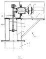
- Fig 1 shows a low frequency sound generator with a feeder unit 1 and a resonator 2, only fragmentarily shown in the figure.
- the resonator 2 preferably consists of a quarter wave resonance tube open at one end and closed at the other end, or a half wave resonance tube which is closed at both ends.
- a feeder unit 1 installed in connection with the closed end of the resonator.
- the main parts of the feeder unit consist of a driving part with a motor 3, whose drive shaft 11 via a coupling 4 is connected to a shaft 5.
- a flywheel 6 On the shaft 5 there is a flywheel 6 attached, which in its turn is equipped with a number of holes for optional mounting of a piston rod 7.
- Fig 2 shows the driving part of the feeder unit with a motor 3, which is carried by a support fastened on to the cylinder block 10.
- the drive shaft of the motor 11 is connected via the coupling 4 to the shaft 5.
- the coupling 4 is e.g. of rubber or other flexible material in order to absorb any angle, axial and/or radial play that may occur between the drive shaft 11 of the motor 3 and the shaft 5. It also carries torque variations, which are caused partly by the inertia of the piston and partly by the sinusoidal load consisting of pressure variations in the resonance tube which have not already been eliminated by the flywheel.
- the shaft 5 is carried by a bearing housing 12 which in its turn is fastened, with a right angle bracket 13, to that end of the cylinder block 10 which is turned away from the resonance tube 2.
- the bearing housing 12 can e.g. be mounted on the bracket 13 with a bolted joint or it could be welded on to it.
- a flywheel 6 detachably connected on the end of the shaft 5 which is turned away from the motor 3 .
- This flywheel is, at different distances from its centre hole, equipped with holes for optional, detachable connection of the piston rod 7.
- the piston rod is mounted with bearings on a screw 14, with which it is attached to the flywheel 6, and by means of the screw 14 being drawn through one of the holes in the flywheel 6 made for this purpose, the screw being fixed with the help of a locking nut 15.
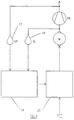
- Fig 4 shows the control system for controlling the flywheel and thereby the movement of the piston.
- the control system is based upon the utilization of the phase difference between the sound pressure measured at the end of the resonance tube 2 which is turned towards the cylinder block 10, and the speed of the piston.
- Said sound pressure is measured preferably with at least one gas pressure transducer 17 and the phase of the piston speed is preferably measured with at least one position sensor 18 mounted in connection with the flywheel.
- the phase for the piston speed corresponds to the phase of the position of the piston with a 90° displacement.
- the measured values are compared by means of a signal comparator 19, which then will send a control signal influencing a speed regulation device 20 connected to the motor 3.
- the transducer as well as the signal comparator and speed regulation device are preferably electronic.
Landscapes
- Physics & Mathematics (AREA)
- Engineering & Computer Science (AREA)
- Acoustics & Sound (AREA)
- Multimedia (AREA)
- Apparatuses For Generation Of Mechanical Vibrations (AREA)
- Toys (AREA)
- Exhaust Silencers (AREA)
- Reciprocating Pumps (AREA)
- Control Of Multiple Motors (AREA)
- Electrostatic, Electromagnetic, Magneto- Strictive, And Variable-Resistance Transducers (AREA)
Claims (12)
- Verfahren zur Steuerung eines Niederfrequenz-Schallgenerators, zu dem ein Resonator (2) und eine Speiseeinheit (1) gehören, mit einem verschiebbaren Kolben (8) mit einem annähernd sinusförmigen Schallfluß zur Erzeugung von Gasimpulsen und zu deren Einspeisung in den Resonator, in welchem die genannten Gasimpulse eine stehende Schallwelle im Gas erzeugen, wobei das Verfahren folgende Schritte umfaßt:- Messung der Bewegung des Kolbens (8),- Messung der Änderung des Schalldrucks, der von den Gasimpulsen im Resonator erzeugt wird,- Vergleich der genannten Bewegung und der genannten Änderung,- Berechnung der Phasenverschiebung zwischen der genannten Bewegung und der genannten Änderung,- Vergleich der genannten Phasenverschiebung mit einem vorgegebenen, aber einstellbaren Wert für die Phasenverschiebung und- Anpassung der genannten Bewegung des Kolbens (8) in solcher Weise, daß sie die genannte vorgegebene, aber einstellbare Phasenverschiebung annimmt.
- Steuereinheit für einen Niederfrequenz-Schallgenerator, zu dem ein Resonator (2) und eine Speiseeinheit (1) gehören, mit einem verschiebbaren Kolben (8) mit einem annähernd sinusförmigen Schallfluß zur Erzeugung von Gasimpulsen und zu deren Einspeisung in den Resonator, in welchem die genannten Gasimpulse eine stehende Schallwelle im Gas erzeugen, mit einer Einrichtung (18) zur Messung der Bewegung des Kolbens, einer Einrichtung (17) zur Messung der Änderung des Schalldrucks, welcher von den Gasimpulsen im Resonator verursacht wird, einer Einrichtung (19) zum Vergleich der genannten Bewegung und der genannten Änderung, einer Einrichtung zur Berechnung der Phasenverschiebung zwischen der genannten Bewegung und der genannten Änderung, einer Einrichtung zum Vergleich der genannten Phasenverschiebung mit einem vorgegebenen, aber einstellbaren Wert für die Phasenverschiebung und einer Einrichtung (20) zur Anpassung der Bewegung des Kolbens (8) an die genannte vorgegebene, aber einstellbare Phasenverschiebung.
- Steuereinheit nach Anspruch 2, dadurch gekennzeichnet, daß die Einrichtung zur Messung der Bewegung des Kolbens (8) einen Lagegeber (18) enthält.
- Steuereinheit nach einem der Ansprüche 2 oder 3, dadurch gekennzeichnet, daß die Einrichtung zur Messung der Änderung des Schalldrucks der von den Gasimpulsen im Resonator verursacht wird, mindestens einen Druckgeber (17) enthält.
- Steuereinheit nach einem der Ansprüche 2 bis 4, dadurch gekennzeichnet, daß die genannte Einrichtung zum Vergleich der genannten Bewegung und der genannten Änderung, die genannte Einrichtung zur Berechnung der Phasenverschiebung zwischen der genannten Bewegung und der genannten Änderung und die genannte Einrichtung zum Vergleich der genannten Phasenverschiebung mit einem vorgegebenen, aber einstellbaren Wert für die Phasenverschiebung in mindestens einem Signalvergleicher (19) zusammengefaßt sind, welcher von dem Lagegeber und dem Druckgeber Signale erhält und auch ein Steuersignal an die genannte Einrichtung zur Anpassung der Bewegung des Kolbens (8) liefert.
- Steuereinheit nach einem der Ansprüche 2 bis 5, dadurch gekennzeichnet, daß der vorgegebene wert für die Phasenverschiebung gleich Null ist.
- Steuereinheit nach einem der Ansprüche 2 bis 5, dadurch gekennzeichnet, daß der vorgegebene Wert für die Phasenverschiebung von Null verschieden ist.
- Niederfrequenz-Schallgenerator mit einer Steuereinheit nach einem der Ansprüche 2 bis 7.
- Niederfrequenz-Schallgenerator nach Anspruch 8, dadurch gekennzeichnet, daß die genannte Speiseeinheit auch einen Zylinder (9) enthält, in welchem der genannte Kolben (8) eine hin- und hergehende Bewegung ausführt, daß der genannte Kolben von einem Motor (3) engetrieben wird und daß die Einrichtung zur Anpassung der Bewegung des Kolbens eine Geschwindigkeitsregelvorrichtung (20) enthält, welche die Frequenz des Motors (3) steuert.
- Niederfrequenz-Schallgenerator nach Anspruch 9, dadurch gekennzeichnet, daß der Kolben (8) an einer Kolbenstange (7) angebracht ist, daß die Kolbenstange lösbar und veränderlich an einem Schwungrad (6) befestigt ist und daß das Schwungrad (6) auf der Welle (5) montiert ist, welche vom Motor (3) angetrieben wird.
- Niederfrequenz-Schallgenerator nach Anspruch 9 oder 10, dadurch gekennzeichnet, daß der Druckgeber (17), der Signalvergleicher (19) und die Geschwindigkeitsregelvorrichtung (20) elektronischer Art sind.
- Niederfrequenz-Schallgenerator nach Anspruch 10, dadurch gekennzeichnet, daß der Lagegeber (18) einen Detektor enthält, der in Verbindung mit dem Schwungrad (6) angeordnet ist.
Applications Claiming Priority (3)
| Application Number | Priority Date | Filing Date | Title |
|---|---|---|---|
| SE8802452 | 1988-06-29 | ||
| SE8802452A SE462374B (sv) | 1988-06-29 | 1988-06-29 | Reglerstyrd motordriven laagfrekvensljudgenerator |
| PCT/SE1989/000366 WO1990000095A1 (en) | 1988-06-29 | 1989-06-27 | Frequency controlled motor driven low frequency sound generator |
Publications (2)
| Publication Number | Publication Date |
|---|---|
| EP0422065A1 EP0422065A1 (de) | 1991-04-17 |
| EP0422065B1 true EP0422065B1 (de) | 1996-02-28 |
Family
ID=20372777
Family Applications (1)
| Application Number | Title | Priority Date | Filing Date |
|---|---|---|---|
| EP89907362A Expired - Lifetime EP0422065B1 (de) | 1988-06-29 | 1989-06-27 | Steuerwerk für niederfrequenzschallgenerator |
Country Status (8)
| Country | Link |
|---|---|
| US (1) | US5109948A (de) |
| EP (1) | EP0422065B1 (de) |
| JP (1) | JPH03505422A (de) |
| AT (1) | ATE134537T1 (de) |
| AU (1) | AU3848989A (de) |
| DE (1) | DE68925817D1 (de) |
| SE (1) | SE462374B (de) |
| WO (1) | WO1990000095A1 (de) |
Families Citing this family (23)
| Publication number | Priority date | Publication date | Assignee | Title |
|---|---|---|---|---|
| SE463785B (sv) * | 1988-11-01 | 1991-01-21 | Infrasonik Ab | Foerfarande och anordning foer att med hjaelp av laagfrekvent ljud forcera vaermetransmission mellan kroppar och gaser |
| SE9001768D0 (sv) * | 1990-05-16 | 1990-05-16 | Infrasonik Ab | Roterande matningsenhet foer infraljudgenerator |
| CN1149325A (zh) * | 1994-05-02 | 1997-05-07 | 欧文斯科尔宁格公司 | 利用高速旋转转筒和低频声波分布的棉块成型工艺 |
| US5595585A (en) | 1994-05-02 | 1997-01-21 | Owens Corning Fiberglas Technology, Inc. | Low frequency sound distribution of rotary fiberizer veils |
| RU2116846C1 (ru) * | 1997-04-22 | 1998-08-10 | Борисов Юлиан Ярославович | Низкочастотный поршневой излучатель |
| SE518168C2 (sv) * | 2000-03-16 | 2002-09-03 | A2 Acoustics Ab | Förfarande och anordning för alstrande av ljud med låg frekvens jämte användning av en sådan anordning |
| JP2002018357A (ja) * | 2000-07-11 | 2002-01-22 | Sasakura Engineering Co Ltd | 低周波音波の発生装置 |
| US20020094274A1 (en) * | 2000-09-15 | 2002-07-18 | Terpay Gregory Weston | Passive device for noise reduction |
| DE102007003166B4 (de) * | 2007-01-22 | 2009-01-29 | Siemens Ag | Lautsprecher, Lautsprechersystem sowie Verfahren zur Erzeugung von akustischen Schwingungen |
| JP2011205408A (ja) * | 2010-03-25 | 2011-10-13 | Railway Technical Research Institute | 低周波音発生装置 |
| KR102304112B1 (ko) * | 2013-09-30 | 2021-09-23 | 코컴 소닉스 에이비 | 사운드 에미터 |
| WO2015133966A1 (en) * | 2014-03-06 | 2015-09-11 | Infrafone Ab | A method of and means for optimizing the operating time of a low frequency sound generator |
| SE543318C2 (en) | 2018-06-21 | 2020-11-24 | Mats Olsson | Method and system for cooling hot objects |
| US10681488B1 (en) * | 2019-03-03 | 2020-06-09 | xMEMS Labs, Inc. | Sound producing apparatus and sound producing system |
| US12075213B2 (en) | 2021-01-14 | 2024-08-27 | xMEMS Labs, Inc. | Air-pulse generating device |
| US12309548B2 (en) | 2021-01-14 | 2025-05-20 | xMEMS Labs, Inc. | Air-pulse generating device with efficient propagation |
| US11445279B2 (en) * | 2021-01-14 | 2022-09-13 | xMEMS Labs, Inc. | Air-pulse generating device and sound producing method thereof |
| US11943585B2 (en) | 2021-01-14 | 2024-03-26 | xMEMS Labs, Inc. | Air-pulse generating device with common mode and differential mode movement |
| US12356141B2 (en) | 2021-01-14 | 2025-07-08 | xMEMS Labs, Inc. | Air-pulse generating device, wearable sound device, bladeless fan, and airflow producing method |
| US12262177B2 (en) | 2021-01-14 | 2025-03-25 | xMEMS Labs, Inc. | Air-pulse generating device producing asymmetric air pulses |
| US11743659B2 (en) | 2021-01-14 | 2023-08-29 | xMEMS Labs, Inc. | Air-pulse generating device and sound producing method thereof |
| US12261567B2 (en) | 2021-01-14 | 2025-03-25 | xMEMS Labs, Inc. | Demodulation signal generator for air pulse generator |
| SE546902C2 (en) | 2021-02-02 | 2025-03-04 | Tallstam Ab | A revolving valve for feeding air pulses to a resonance tube for generating low-frequency sound and a method for feeding these pulses at the resonance frequency of the resonance tube |
Family Cites Families (8)
| Publication number | Priority date | Publication date | Assignee | Title |
|---|---|---|---|---|
| US1173708A (en) * | 1915-09-23 | 1916-02-29 | Henry M Chance | Method for burning fuel. |
| SU624659A1 (ru) * | 1977-04-22 | 1978-09-25 | Предприятие П/Я В-8584 | Устройство дл излучени акустических колебаний |
| EP0006833B1 (de) * | 1978-07-03 | 1983-09-14 | Mats Olsson Konsult Ab | Niederfrequenz Schallgeber |
| SE425597B (sv) * | 1980-10-13 | 1982-10-18 | Ekstroms Vermetekniska Ab | Tvangsstyrd ljudalstrare for infraljudomradet |
| US4307964A (en) * | 1981-02-25 | 1981-12-29 | The United States Of America As Represented By The Secretary Of The Interior | System for maintaining high resonance during sonic agglomeration |
| DE8712331U1 (de) * | 1986-09-26 | 1988-01-28 | Flowtec AG, Reinach, Basel | Corioliskraft-Massendurchflussmesser |
| SE463994B (sv) * | 1986-10-31 | 1991-02-18 | Prodeo Ab | Motordriven vissla |
| SE457240B (sv) * | 1987-04-08 | 1988-12-12 | Infrasonik Ab | Luftdriven positivt aaterkopplad laagfrekvensljudgenerator |
-
1988
- 1988-06-29 SE SE8802452A patent/SE462374B/sv not_active IP Right Cessation
-
1989
- 1989-06-27 US US07/634,142 patent/US5109948A/en not_active Expired - Fee Related
- 1989-06-27 EP EP89907362A patent/EP0422065B1/de not_active Expired - Lifetime
- 1989-06-27 AU AU38489/89A patent/AU3848989A/en not_active Abandoned
- 1989-06-27 AT AT89907362T patent/ATE134537T1/de not_active IP Right Cessation
- 1989-06-27 JP JP1507088A patent/JPH03505422A/ja active Pending
- 1989-06-27 DE DE68925817T patent/DE68925817D1/de not_active Expired - Lifetime
- 1989-06-27 WO PCT/SE1989/000366 patent/WO1990000095A1/en not_active Ceased
Also Published As
| Publication number | Publication date |
|---|---|
| EP0422065A1 (de) | 1991-04-17 |
| US5109948A (en) | 1992-05-05 |
| JPH03505422A (ja) | 1991-11-28 |
| SE462374B (sv) | 1990-06-18 |
| SE8802452D0 (sv) | 1988-06-29 |
| SE8802452L (sv) | 1989-12-30 |
| DE68925817D1 (de) | 1996-04-04 |
| AU3848989A (en) | 1990-01-23 |
| ATE134537T1 (de) | 1996-03-15 |
| WO1990000095A1 (en) | 1990-01-11 |
Similar Documents
| Publication | Publication Date | Title |
|---|---|---|
| EP0422065B1 (de) | Steuerwerk für niederfrequenzschallgenerator | |
| JP3122155B2 (ja) | 駆動機構 | |
| US6742960B2 (en) | Vibratory compactor and method of using same | |
| JP3841450B2 (ja) | 質量ばね装置および振動慣性力発生器 | |
| US4981425A (en) | Device for ultrasonic atomization of a liquid medium | |
| US4378064A (en) | Three mass electromagnetic feeder | |
| US5029011A (en) | Engraving apparatus with oscillatory movement of tool support shaft monitored and controlled to reduce drift and vibration | |
| US5979640A (en) | Vibrating conveyor drive with continuously adjustable stroke | |
| US3224086A (en) | Method of high frequency vibration fitting | |
| DE601527T1 (de) | Anlage zum Kontrollieren der höheren Oberwellenschwingungen in den Rotorblättern eines Hubschraubers. | |
| US4388981A (en) | Variable cylinder hydraulic vibrator and control system | |
| US20060034657A1 (en) | Control system and method for a vibratory mechanism | |
| EP0345804B1 (de) | Hydrostatischer Lautsprecher und Lautsprecherantrieb | |
| US3716130A (en) | Variable voltage resilient connecting rod drive | |
| US4539845A (en) | Driving system for exciting a mechanical component at its resonant frequency for fatigue-testing purposes | |
| AU614516B2 (en) | Air-driven low-frequency sound generator with positive feedback system | |
| US4506758A (en) | High frequency reaction mass and hydraulic cylinder assembly | |
| USRE32995E (en) | Variable cylinder hydraulic vibrator and control system | |
| CN211275402U (zh) | 一种振动筛装置 | |
| JPH01234144A (ja) | 超音波加工振動装置 | |
| EP0035014A1 (de) | Hydraulisches vibrator- und steuerungssystem mit variablem zylinder | |
| JP2588923Y2 (ja) | 多点加振式振動試験装置 | |
| SU748310A1 (ru) | Вибратор дл сейсмических исследований | |
| JPS5998928A (ja) | 高周波振動杭打機の発生振動数の制御装置 | |
| SU971604A1 (ru) | Регул тор подачи |
Legal Events
| Date | Code | Title | Description |
|---|---|---|---|
| PUAI | Public reference made under article 153(3) epc to a published international application that has entered the european phase |
Free format text: ORIGINAL CODE: 0009012 |
|
| 17P | Request for examination filed |
Effective date: 19910129 |
|
| AK | Designated contracting states |
Kind code of ref document: A1 Designated state(s): AT BE CH DE FR GB IT LI LU NL |
|
| RAP1 | Party data changed (applicant data changed or rights of an application transferred) |
Owner name: INFRASONIK AB |
|
| 17Q | First examination report despatched |
Effective date: 19940715 |
|
| GRAA | (expected) grant |
Free format text: ORIGINAL CODE: 0009210 |
|
| AK | Designated contracting states |
Kind code of ref document: B1 Designated state(s): AT BE CH DE FR GB IT LI LU NL |
|
| PG25 | Lapsed in a contracting state [announced via postgrant information from national office to epo] |
Ref country code: LI Effective date: 19960228 Ref country code: BE Effective date: 19960228 Ref country code: AT Effective date: 19960228 Ref country code: IT Free format text: LAPSE BECAUSE OF FAILURE TO SUBMIT A TRANSLATION OF THE DESCRIPTION OR TO PAY THE FEE WITHIN THE PRE;WARNING: LAPSES OF ITALIAN PATENTS WITH EFFECTIVE DATE BEFORE 2007 MAY HAVE OCCURRED AT ANY TIME BEFORE 2007. THE CORRECT EFFECTIVE DATE MAY BE DIFFERENT FROM THE ONE RECORDED.SCRIBED TIME-LIMIT Effective date: 19960228 Ref country code: FR Effective date: 19960228 Ref country code: NL Free format text: LAPSE BECAUSE OF FAILURE TO SUBMIT A TRANSLATION OF THE DESCRIPTION OR TO PAY THE FEE WITHIN THE PRESCRIBED TIME-LIMIT Effective date: 19960228 Ref country code: CH Effective date: 19960228 |
|
| REF | Corresponds to: |
Ref document number: 134537 Country of ref document: AT Date of ref document: 19960315 Kind code of ref document: T |
|
| REF | Corresponds to: |
Ref document number: 68925817 Country of ref document: DE Date of ref document: 19960404 |
|
| PG25 | Lapsed in a contracting state [announced via postgrant information from national office to epo] |
Ref country code: DE Effective date: 19960529 |
|
| PG25 | Lapsed in a contracting state [announced via postgrant information from national office to epo] |
Ref country code: GB Effective date: 19960627 |
|
| PG25 | Lapsed in a contracting state [announced via postgrant information from national office to epo] |
Ref country code: LU Free format text: LAPSE BECAUSE OF NON-PAYMENT OF DUE FEES Effective date: 19960630 |
|
| EN | Fr: translation not filed | ||
| NLV1 | Nl: lapsed or annulled due to failure to fulfill the requirements of art. 29p and 29m of the patents act | ||
| REG | Reference to a national code |
Ref country code: CH Ref legal event code: PL |
|
| PLBE | No opposition filed within time limit |
Free format text: ORIGINAL CODE: 0009261 |
|
| STAA | Information on the status of an ep patent application or granted ep patent |
Free format text: STATUS: NO OPPOSITION FILED WITHIN TIME LIMIT |
|
| 26N | No opposition filed | ||
| GBPC | Gb: european patent ceased through non-payment of renewal fee |
Effective date: 19960627 |