EP0422257A1 - Machine d'insertion d'encarts avec dispositif d'application de colle - Google Patents
Machine d'insertion d'encarts avec dispositif d'application de colle Download PDFInfo
- Publication number
- EP0422257A1 EP0422257A1 EP89118719A EP89118719A EP0422257A1 EP 0422257 A1 EP0422257 A1 EP 0422257A1 EP 89118719 A EP89118719 A EP 89118719A EP 89118719 A EP89118719 A EP 89118719A EP 0422257 A1 EP0422257 A1 EP 0422257A1
- Authority
- EP
- European Patent Office
- Prior art keywords
- signature
- drive system
- conveyor chain
- auxiliary
- sprocket wheel
- Prior art date
- Legal status (The legal status is an assumption and is not a legal conclusion. Google has not performed a legal analysis and makes no representation as to the accuracy of the status listed.)
- Withdrawn
Links
- 230000007246 mechanism Effects 0.000 claims abstract description 27
- 239000000853 adhesive Substances 0.000 claims abstract description 23
- 230000001070 adhesive effect Effects 0.000 claims abstract description 23
- 239000011324 bead Substances 0.000 claims abstract description 12
- 238000012546 transfer Methods 0.000 claims description 12
- 230000008859 change Effects 0.000 claims description 4
- 239000003292 glue Substances 0.000 description 7
- 125000006850 spacer group Chemical group 0.000 description 5
- WVQBLGZPHOPPFO-LBPRGKRZSA-N (S)-metolachlor Chemical compound CCC1=CC=CC(C)=C1N([C@@H](C)COC)C(=O)CCl WVQBLGZPHOPPFO-LBPRGKRZSA-N 0.000 description 4
- 210000005069 ears Anatomy 0.000 description 2
- 230000000694 effects Effects 0.000 description 2
- 239000012943 hotmelt Substances 0.000 description 2
- 238000000034 method Methods 0.000 description 2
- 238000012986 modification Methods 0.000 description 2
- 230000004048 modification Effects 0.000 description 2
- 239000004831 Hot glue Substances 0.000 description 1
- 230000000712 assembly Effects 0.000 description 1
- 238000000429 assembly Methods 0.000 description 1
- 238000011161 development Methods 0.000 description 1
- 238000006073 displacement reaction Methods 0.000 description 1
- 210000003414 extremity Anatomy 0.000 description 1
- 210000003141 lower extremity Anatomy 0.000 description 1
- 230000008569 process Effects 0.000 description 1
- 230000001360 synchronised effect Effects 0.000 description 1
- 238000009966 trimming Methods 0.000 description 1
- 210000001364 upper extremity Anatomy 0.000 description 1
Images




Classifications
-
- B—PERFORMING OPERATIONS; TRANSPORTING
- B42—BOOKBINDING; ALBUMS; FILES; SPECIAL PRINTED MATTER
- B42C—BOOKBINDING
- B42C1/00—Collating or gathering sheets combined with processes for permanently attaching together sheets or signatures or for interposing inserts
- B42C1/10—Machines for both collating or gathering and interposing inserts
Definitions
- This invention relates to an on-line tipping apparatus for use with a signature inserting machine. More particularly, the invention relates to an on-line tipping apparatus which has a slave drive system run by the main conveyor chain drive system of the signature inserting machine.
- Booklets such as magazines, manuals and catalogs are assembled on a commercial scale by automated systems. Typically, sections of the booklet are assembled and bound by one machine. Each section consists of two or more sheets and is commonly referred to in the industry as a signature.
- a signature inserting machine includes a series of hoppers positioned side by side above a conveyor chain.
- the hoppers contain signatures. They are generally continually hand loaded or machine loaded throughout a run.
- a stationary member known as a saddle is positioned above portions of the conveyor chain and adjacent each hopper.
- the saddles are formed in a generally inverted V shape for receiving partially opened signatures from its associated hopper.
- the conveyor chain also includes several signature engaging pusher pins which are moved in sequence past the saddles to engage a signature and push it along. As a signature is picked from a saddle by the pusher pins of the conveyor chain, that signature is deposited on top of other signatures previously picked from saddles and being moved by the same pusher pin of the conveyor chain.
- a typical saddle machine has at least four hoppers which contain the signatures to be assembled. After the last signature, usually the front and back cover pages, is deposited onto previous signatures, the assembled booklet passes through a station which permanently binds it. Stapling or stitching are two examples of binding steps for booklets. Thereafter, the booklet is transferred to a trimming machine that trims its top, bottom and front edges.
- the inserts usually differ in size than a signature page and therefor are conspicuous. They are typically used for an advertising or other related purpose.
- the industry has used various types of machines for adding or, as commonly used, tipping an insert to a signature page.
- a separate machine is utilized to tip i.e., glue an insert to a page of a signature.
- the signatures are transported to the tipping machine for the sole purpose of adding an insert. Thereafter the signatures are taken to the signature inserting machine and the signatures completely assembled to form the booklet.
- the apparatus must be flexible enough to be operable with different makes of signature inserting machines. Additionally, the apparatus must be able to properly apply the inserts in a precise location. Most importantly, the apparatus must be capable of being adjusted so as to be in perfect timing with the conveyor chain of the inserting machine.
- an on-line tipping apparatus which is portable in nature and provides the features which are required.
- An on-line tipping apparatus is intended for use with a signature inserting machine.
- the apparatus is portable in that it is adapted to be moved into operable association with a conventional signature inserting machine when needed.
- the apparatus has an auxiliary chain drive system which is run by a main conveyor chain drive system of the signature inserting machine.
- the on-line tipping apparatus comprises a frame assembly which is capable of being readily moved.
- a base mounted on the frame assembly accommodates the auxiliary chain drive system.
- the base is capable of vertical movement for approximate positioning of the auxiliary chain drive system with the main conveyor chain drive system of the signature inserting machine.
- Associated with the frame assembly is a raceway with elongated flat saddles.
- An adhesive applying mechanism is also operably associated with the frame assembly for directing a bead of adhesive to a signature as it passes along the raceway.
- the elongated flat saddles positioned above the raceway receives an insert in a proper position for adhering to the signature.
- the auxiliary chain drive system comprises an endless conveyor chain which has adjustable timed connection means with the main conveyor chain for ensuring the insert is properly positioned when adhered to the signature.
- FIG. 1 shows the on-line tipping apparatus when operably connected to a typical signature inserting machine.
- Booklets such as magazines, manuals, catalogues and brochures are assembled and have added thereto one or more inserts by the apparatus of this invention.
- the inserts added can contain multiple pages and virtually be any size or shape.
- a magazine is depicted in the process of being assembled wherein one page of a signature has a single sheet insert adhered thereto. The description which follows describes the apparatus of this invention when used for this purpose.
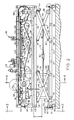
- FIGS. 2-11 disclose the on-line tipping apparatus when removed from the signature inserting machine.
- the on-line tipping apparatus of this invention is shown in operable association with a signature inserting machine.
- the signature inserting machine shown is typical of such machines.
- a signature 11 is picked from a saddle 12 and positioned in a generally inverted V orientation on a moving main conveyor chain 13.
- the chain 13 is an endless conveyor chain driven by a power source and guided by sprocket wheels (not shown) to travel in a longitudinal path the length of the signature inserting machine.
- Pusher pins 14 on the conveyor chain engage a deposited signature on the saddle and drive it along.
- Guide wires 15 extending outwardly from the conveyor chain guide to a center of the booklet forces a half-section of the booklet as assembled at that point towards a horizontal position to ride onto a raceway of the on-line tipping apparatus.
- Signature hoppers 20, 21 and 22 each contains a supply of folded signatures.
- a signature extractor means (not shown) is provided on each hopper to remove a single signature from a hopper and deposit it on the saddle 12 over conveyor chain 13.
- the pusher pin 14 picks the signature off the saddle causes it to drop onto conveyor chain 13.
- Each succeeding signature is deposited on top of assembled signatures moving along the conveyor chain 13.
- the signatures are loaded in the hoppers in an on-edge or flat condition with a folded edge lowermost.
- Several hoppers on the machine are provided, one for each additional signature. Obviously, the signatures are placed in the successive hoppers in a sequence which results in a magazine in proper order.
- the last hopper contains a signature which represents the front and back cover pages of the booklet.
- the assembled or inserted signatures taken from the conveyor chain after the last hopper are stitched, stapled or otherwise bound, trimmed in-line, and packaged for delivery.
- a hopper typically positioned between hoppers 20 and 28 is removed to accommodate the on-line tipping apparatus of this invention. Additionally, a portion of a chain carrier which supports the main conveyor chain 13 is removed to receive the take-off drive system of the on-line tipping apparatus, as explained in further detail below.
- a glue gun 23 applies a bead of adhesive to a signature page. The glue gun is fed by hose 24 leading from hot melt adhesive reservoir 25 in a controlled fashion by operation of control box 26. An insert 27 from hopper 28 is properly positioned over a page of the signature with the adhesive bead and adhered thereto. Additional signatures are fed onto the saddles associated with conveyor chain 13 from hoppers 21, 22 and subsequent hoppers (not shown).
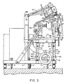
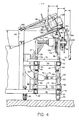
- the on-line tipper apparatus shown in FIG. 1 and in greater detail in FIGS. 2-4 is portable in nature. That is, it can be stored in a remote location when not need, but readily moved and connected to a conventional signature inserting machine when needed.
- the apparatus is usable with several models of signature inserting machines made by different manufacturers because of various adjusting mechanisms built into the apparatus.
- the apparatus comprises a frame assembly 30 with caster wheels mounted at each of the lower four corners of the frame assembly.
- the frame assembly serves the function of providing a base to which the various components of the apparatus are mounted. It comprises longitudinal base members 31, 32 and 33, lower cross bars 34, 35, 36, 37, 38, 39 and 40, longitudinal upper members 41 and 42, upper cross bars 43 and 44, and vertical support members 45 and 46.
- the frame members preferably made from hollow structural tubing, are attached e.g., by weldments or bolts and nuts to one another to form a unitary structure of sufficient strength for its intended function.
- Slotted braces 47 are pivotably attached to cross bars 34 and 40 at a lower extremity and adjustably attached to cross bars 43 and 44 near an upper extremity. The braces allow the upper members of the frame assembly to be vertically adjusted according to need, yet provide a degree of stability when bolt heads 48 are forced into engagement with the slot edges.
- Caster wheels 50 are mounted on the frame assembly at each of the frame assembly corners. Other wheel means can readily be used.
- An anchor bolt 51 is positioned in at least one lower member of the frame assembly so as to engage the floor surface upon tightening. This anchors or secures the apparatus once it is initially positioned.
- Other securing means such as roller blocks, etc. can as well be used.
- a drive system base 52 is mounted on the upper members 41 and 42 and upper cross bars 43 and 44 of the frame assembly.
- the drive system base is comprised of plates 53 and 54 at each end of the longitudinal upper members and upper cross bars together with connecting rails 55 and 56 extending between the plates.
- the base is provided to accommodate an auxiliary chain drive system.
- a series of bolt holes 57 near the outside edges of the plates allows some lateral positioning of the base relative to the frame assembly depending on the particular signature inserting machine which is being used.
- the drive system base 52 is also capable of vertical movement relative to the base members of the frame assembly.
- the vertical movement feature is used for the purpose of approximate positioning of the auxiliary chain drive system with the main conveyor chain drive system of the signature inserting machine.
- Scissor lifter means 60 at each end of the platform are provided for the vertical movement.
- Lower arm pivot brackets 61 are secured to longitudinal base members 32 and 33. Pivot pin 62 holds one end of each lifter bar 63 in pivotable engagement.
- Upper arm pivot brackets 61 positioned on the longitudinal upper members 41 and 42 substantially directly above lower arm pivot brackets 61 are used to hold each lifter bar 64 in pivotable engagement.
- a shoulder bolt 65 in the center of lifter bars 63 and 64 holds the two bars together in a scissors fashion.
- a second shoulder bolt 65 on the backside of the apparatus on the same end also holds together the second set of lifter bars.
- Spacers 66 and spacer bar 67 receives each shoulder bolt.
- Rollers 68 and 69 at the non-pivot ends of the lifter bars ride along base members 31 and 32 and longitudinal upper members 41 and 42, respectively.
- Crank wheel 70 is connected to the scissor lifter means 60 by screw member 71 and brawl bar 72.
- Screw member 71 extends through bearing block 73 and is threaded into brawl bar 72.
- the brawl bar 72 is secured to both rollers 68.
- Turning the crank wheel 70 will cause the screw member 71 to draw the brawl bar 72 towards or away from the wheel depending on the direction turned.
- the ends of the lifter bars 64 are caused to laterally move which causes the cooperatively acting part of the scissor means, i.e., lifter bar 63 to raise or lower.
- crank wheel 70 Motion from the two sets of lifter bars adjacent the crankwheel is transferred to the opposite sets of lifter bars by means of left hand screw member 75, turnbuckle 76, and right hand screw member 77.
- the outer extremity of each of these screws is attached to spacer bars 67. As such, turning of the crank wheel 70 causes all four sets of scissor lifter bars to substantially simultaneously operate.
- auxiliary chain drive system mounted on drive system base 52 is an auxiliary chain drive system.
- the system comprises a power take-off assembly and an endless auxiliary conveyor chain assembly.
- the power take-off assembly is capable of transferring power from the main conveyor chain of the signature inserting machine to the auxiliary conveyor chain. Adjusting means as described in following paragraphs are built into the assemblies to ensure that the drive systems are synchronized and that pusher pins on the main conveyor chain and the auxiliary conveyor chain are compatible.
- the power take-off assembly uses a take-off sprocket wheel 80, an endless transfer chain 81, and a power transfer wheel 82 to transmit power to the auxiliary conveyor chain assembly.
- Take-off sprocket wheel 80 and power transfer wheel 82 are fixed together and each mounted on shaft 83 along with bearings.
- the transfer chain 81 which is driven by wheel 82 transfers power to drive wheel 86.
- Shaft 87 with drive wheel 86 is mounted on pylons 88.
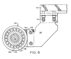
- a pivot arm 89 is used to adjustably position the take-off sprocket wheel 80 and power transfer wheel 82. As best seen in FIGS. 2, 3 and 5, the pivot arm 89 has a first set of ears 90 which are pivotably mounted on shaft 87. The other end of the pivot arm has a second set of ears 91 adapted to hold shaft 83, along with the take-off sprocket wheel 80 and power transfer wheel 82 mounted thereon.
- a height adjusting mechanism 95 is operably connected to the pivot arm 89 to move it about its pivot point relative to the drive system base 52. This allows the take-off sprocket wheel 80 to properly mesh with the main conveyor chain.
- the scissor lifter bars are used for approximate positioning of the take-off sprocket wheel and the adjusting mechanism 95 is used to cause the teeth of the sprocket wheel to mesh with the links of the main conveyor chain.
- Adjusting mechanism 95 comprises a turn screw 96 in operable engagement at one end with pivot arm 89.
- the turn screw extends through bracket 97 which in turn is attached to the base 52.
- Internally threaded turn knob 98 is positioned on the turn screw and in engagement with bracket 97. Adjusting of the turn knob 98 causes the pivot arm 89 to move up or down about its pivot point. This allows take-off sprocket wheel 80 to be engaged or disengaged from the main conveyor chain of the signature inserting machine.
- FIG. 2 shows take-off sprocket wheel 80 in a fully raised position in dotted lines.
- a slide block synchronization assembly 100 is also provided to advance transfer chain 81 a fraction of a chain link if needed.
- the assembly comprises an adjusting wheel 101, idle wheel 102, slide block 103 and sprocket wheels 104.
- the slide block has a gear rack 105 to receive gear teeth of the idle wheel. Movement of the adjusting wheel 101 causes slide block 103 with sprocket wheels 104 mounted thereon to move up or down. This in turn causes the sprocket wheel 104 to change its point of engagement with transfer chain 81.
- the endless auxiliary conveyor chain assembly comprises an endless conveyor chain 110 with sprocket wheels 111 and 112, idle wheels 113 and adjusting idle wheel 114.
- Each sprocket wheel revolves about a threaded shaft 117.
- the shafts are mounted above the drive system base by means of the pylons 88.
- Idle wheels 113 are mounted on hanging brackets 115 which are attached to rail 116.
- Rail 116 extends between sprocket wheels 111 and 112.
- Adjusting idle wheel 114 is mounted for adjustable movement to accommodate different sized conveyor chains and chain stretching which may occur.
- the adjustment means comprises left hand screw member 119, right hand screw member 120 and turnbuckle 121.
- Tension bar 122 is pivotably attached to mounting bracket 123 found on the frame assembly.
- the screw members are pivotably attached at one end to the tension arm 122 and at a second end to mounting bracket 123 on rail 116 by use of turnbuckle brackets 124. Turning of the turnbuckle will cause tension arm 122 to move about its pivot point and exert more or less tension on conveyor chain 110 as needed.
- the auxiliary conveyor chain assembly is capable of lateral movement.
- sprocket wheel 111 is mounted on threaded shaft 117 in a fashion which allows it to laterally move on said shaft.
- An auxiliary drive hub assembly 130 is positioned on shaft 117 by use of a threaded hub 131.
- the hub is provided with a flange 132 at an end adjacent sprocket wheel 111.
- Flange 132 has a series of spaced threaded screw holes around its periphery to provide a means by which it is fixedly attached to sprocket wheel 111.
- the hub and sprocket wheel are held together for revolving motion with shaft 117 by screws 133.
- the internal thread of the hub cooperates with the external thread of shaft 117 to provide longitudinal displacement of hub 131 and sprocket wheel 111 upon shaft 117 when the shaft is held stationary and sprocket wheel 111 is turned.
- a lock nut 134 is used to lock threaded hub 131 upon shaft 117 so that both rotate in unison.
- a pair of ball bearings 135 is used to rotably mount the threaded hub 131 is a bearing housing 136.
- Each member of the pair of ball bearings 135 is held in a fixed spaced relationship within the assembly by hub spacer 136 and housing spacer 137.
- the ball bearings are held upon the hub 131 by means of a jam nut 139.
- a retaining ring 140 retains the bearing housing 136 upon the ball bearings 135, said ring being mounted in a groove cut into the inside diameter of the bearing housing 136.
- the bearing housing 136 has an ear flange 141 extending from one side. Cap screws 142 passing through the ear flange are used to fixedly secure the bearing housing 136 to a support bracket 143 which in turn is attached to rail 116 by screw 144.
- the ball bearings 135 allow the hub 131 and sprocket wheel 111 to rotate with threaded shaft 117 during normal operation while the bearing housing 136 is stationary.
- a set of pusher pins 145 are provided on the auxiliary conveyor drive chain for the purpose of engaging the signatures and inserts and driving them along.
- the adjusting mechanisms of the apparatus allow the pusher pins 145 of the auxiliary conveyor drive chain and the pusher pins 14 of the main conveyor drive chain to simultaneously engage a signature.
- the pusher pins can be removed and mounted at each chain link. Adjustment of pusher pin placements on the auxiliary conveyor chain gives the needed compatibility with pusher pins 14 on the main conveyor chain. As a result a properly positioned insert is added to the signature.
- a raceway 150 is also positioned on the frame assembly.
- the raceway preferably extends substantially the length of the on-line tipping apparatus.
- the raceway serves the function of receiving a half-section of a booklet and providing a flattened surface on which it can travel while receiving a bead of adhesive and an insert.
- the raceway is adjustably mounted on rail 116 to tilt to accommodate various inserts and signatures of different sizes and weights.
- raceway 150 is mounted above drive system base 52 by means of adjusting mechanisms best seen in FIGS 9-11.
- Raceway adjusting mechanisms 155 are positioned in the approximate center of the raceway and near each end. Each mechanism has a slide pinion housing 157 with curved rails 158 and 159.
- Housing 157 is secured to the underside of the elongated raceway 150.
- a roller unit 160 comprised of housing 161 and rollers 162 are positioned on rails 158 and 159, respectively.
- the roller unit is fixedly mounted on rail 116 by use of a bracket 163 and cap screw 164.
- a set screw lock 165 extends in frictional engagement through the housing 161 of each tray adjusting mechanism to lock the mechanisms in place once properly adjusted.
- the raceway can be tilted up to about sixty degrees from the horizontal.
- a rack unit 168 comprised of housing 169, modified rack 170 with a bracket 171, and a raceway extension 172 secured thereto.
- the modified rack works in association with gear wheel 173 mounted on rod 174 to move the raceway extension so as to lengthen or shorten the raceway's working surface as needed.
- Rod 174 extends between all three tray adjusting mechanisms to simultaneously adjust all raceway extensions.
- a lock mechanism 175 locks the raceway extensions to a desired position. This feature is especially useful with large signatures in that it provides a wider flattened surface on which the booklet half-sections ride.
- a mounting bar 180 is used to hold the adhesive applying mechanisms.
- an electric eye sensor 181 and a solenoid glue gun 23 are positioned above elongated raceway 150 and prior to insert hopper 28.
- the sensor and glue gun are part of a conventional adhesive means.
- Control box 26 and hot melt reservoir 25 shown in FIG. 1 together with the sensor and glue gun properly apply a bead of adhesive to a signature. Placement and amount of adhesive are done under controlled conditions in a known fashion.
- a timing compensator mechanism 182 is operably connected to shaft 117 and the control box 26. Such timing compensator mechanisms are well known and commercially available.
- a glue hold down assembly comprised of a roller 183 adjustably mounted on the mounting bar 180 is positioned above the conveyor chain 13 and after the insert hopper 28. Its function is to force the insert into contact with the adhesive bead found on the signature. While not shown, various sensing devices can be provided to disengage the roller 183 if an insert is not present.
- An elongated catch saddle 190 in the form of a right angle rail is positioned above the raceway by means of arm 191 and bracket 192 secured to mounting bar 180.
- the elongated catch saddle 190 together with an optional second elongated catch saddle 193 also extending from arm 191 receive an insert from a hopper and retains it in place until picked up by the pins of the conveyor chains and moved along.
- pusher pins 14 and 145 on the conveyor chains of the main chain drive system and the auxiliary chain drive system simultaneously move the signature, with overlying insert, along the raceway.
- the on-line tipping apparatus is moved into engagement with a signature inserting machine.
- the auxiliary chain drive system is approximately positioned by adjusting its height from the floor surface by use of the scissor lifter means. Thereafter, the turn screw adjusting mechanism is used to further position the take-off sprocket wheel of the auxiliary chain drive system into engagement with the signature inserting machine's main conveyor chain.
- the slide block synchronization assembly is used to advance the auxiliary conveyor chain a fraction of a link if needed.
- the pins on the two conveyor chains are repositioned on the chains if needed to make them compatible when running.
- the raceway of the apparatus is adjusted in its tilt and width depending on the particular signature and insert to be added thereto. If needed, the auxiliary conveyor chain is laterally moved.
- All locking mechanisms are tightened once all features of the tipping apparatus are positioned for operation.
- Supplying power to the signature inserting machine runs its main conveyor chain and simultaneously the auxiliary conveyor chain drive system. Each conveyor chain moves at the same speed with their pusher pins in alignment. Signatures move along the main conveyor chain until they reach the raceway. There, a half-section of the booklet is opened onto the raceway in a flattened state. A bead of adhesive is applied to it and subsequently an insert held above the raceway by the elongated catch saddles is caught by a pusher pin and dropped onto the adhesive bead. Subsequent signatures are added until the end of the machine reached wherein the assembled signatures with insert are bound.
- the apparatus of this invention enjoys many advantages.
- the portable nature of the apparatus allows it to be used as needed.
- the apparatus is simply moved from storage to a conventional signature inserting machine when inserts are to be added.
- Separate signature inserting machines with built-in insert capability or tipping apparatus which are run independently are no longer needed.
- the adjusting mechanisms built into the on-line tipping apparatus of this invention allow it to be used with several makes and models of conventional signature inserting machines.
- the drive system tipping apparatus is fully compatible with the main conveyor chain of the inserting machine because of the fact it is driven by the main conveyor chain.
- the speed and timing of the auxiliary conveyor chain of the tipping apparatus is directly controlled by the main conveyor chain of the inserting machine.
- corner screw lifting means can be used to adjust the height of the platform.
- Adhesive applicators of various designs for hot melt and cold adhesives can also be used as well as various sensing devices and automatic stopping devices.
- the raceway, adhesive applying mechanism and elongated catch saddle can individually or collectively be mounted on the signature inserting machine in operable association with the tipping apparatus.
- Specially constructed floor stands can as well be used to hold the aforesaid components in position with the tipping apparatus to perform their respective functions. Such modifications are intended to be within the scope the claimed invention.
Landscapes
- Engineering & Computer Science (AREA)
- Mechanical Engineering (AREA)
- Collation Of Sheets And Webs (AREA)
- Auxiliary Devices For And Details Of Packaging Control (AREA)
Applications Claiming Priority (1)
| Application Number | Priority Date | Filing Date | Title |
|---|---|---|---|
| US07/237,542 US4917367A (en) | 1988-08-29 | 1988-08-29 | On-line tipping apparatus for a signature inserting machine |
Publications (1)
| Publication Number | Publication Date |
|---|---|
| EP0422257A1 true EP0422257A1 (fr) | 1991-04-17 |
Family
ID=22894180
Family Applications (1)
| Application Number | Title | Priority Date | Filing Date |
|---|---|---|---|
| EP89118719A Withdrawn EP0422257A1 (fr) | 1988-08-29 | 1989-10-09 | Machine d'insertion d'encarts avec dispositif d'application de colle |
Country Status (2)
| Country | Link |
|---|---|
| US (1) | US4917367A (fr) |
| EP (1) | EP0422257A1 (fr) |
Cited By (2)
| Publication number | Priority date | Publication date | Assignee | Title |
|---|---|---|---|---|
| DE10349483A1 (de) * | 2003-10-21 | 2005-06-02 | Heidelberger Druckmaschinen Ag | Einkleben von personalisierten Werbekarten während des Sammelheftens |
| EP1588861A1 (fr) * | 2004-04-23 | 2005-10-26 | Müller Martini Holding AG | Procédé et appareil pour appliquer un produit supplementaire au moins presque plat à une surface laterale d'une signature |
Families Citing this family (3)
| Publication number | Priority date | Publication date | Assignee | Title |
|---|---|---|---|---|
| US5067700A (en) * | 1990-08-10 | 1991-11-26 | The Gray Printing Company | Method and apparatus for attaching inserts to moving sheets |
| US5516090A (en) * | 1994-04-22 | 1996-05-14 | R. R. Donnelley & Sons Company | Mounting arrangement for a binding line |
| DE102006013325A1 (de) * | 2006-03-21 | 2007-09-27 | Hohner Maschinenbau Gmbh | Vorrichtung zum Zusammentragen flacher Druckprodukte |
Citations (1)
| Publication number | Priority date | Publication date | Assignee | Title |
|---|---|---|---|---|
| DE2049850A1 (de) * | 1970-10-10 | 1972-04-27 | Grüner + Jahr GmbH & Co, Druck- und Verlagshaus, 2210 Itzehoe | Vorrichtung zum Einlegen eines Zusatzproduktes, insbesondere eines Blattes oder Heftes in einen Stapel von mindestens teilweise zusammengetragenen Druckbogen |
Family Cites Families (8)
| Publication number | Priority date | Publication date | Assignee | Title |
|---|---|---|---|---|
| US31710A (en) * | 1861-03-19 | Improvement in cultivators | ||
| DE1265763B (de) * | 1961-06-01 | 1968-04-11 | Rudolf Hepp | Verfahren zum Ineinanderstecken und bzw. oder Aufeinandersammeln von Druckbogen, Falzprodukten u. dgl. sowie Vorrichtung zur Durchfuehrung des Verfahrens |
| US3371924A (en) * | 1966-03-07 | 1968-03-05 | Donnelley & Sons Co | Apparatus for tipping inserts into a saddle stitched book |
| US3630513A (en) * | 1969-03-12 | 1971-12-28 | William W Davidson Jr | Automatic tipping machine |
| US3663007A (en) * | 1970-05-07 | 1972-05-16 | Mueller Hans Grapha Masch | Tipping apparatus for a signature gathering machine |
| US3658318A (en) * | 1970-07-10 | 1972-04-25 | Mccall Corp | Method and apparatus for adding loose inserts to magazines |
| US4083551A (en) * | 1976-09-30 | 1978-04-11 | Harris Corporation | Method and apparatus for on-line tipping of inserts |
| USRE31710E (en) | 1977-06-27 | 1984-10-23 | Harris Corporation | Personalized on-line printing and inserting magazine binding machine |
-
1988
- 1988-08-29 US US07/237,542 patent/US4917367A/en not_active Expired - Fee Related
-
1989
- 1989-10-09 EP EP89118719A patent/EP0422257A1/fr not_active Withdrawn
Patent Citations (1)
| Publication number | Priority date | Publication date | Assignee | Title |
|---|---|---|---|---|
| DE2049850A1 (de) * | 1970-10-10 | 1972-04-27 | Grüner + Jahr GmbH & Co, Druck- und Verlagshaus, 2210 Itzehoe | Vorrichtung zum Einlegen eines Zusatzproduktes, insbesondere eines Blattes oder Heftes in einen Stapel von mindestens teilweise zusammengetragenen Druckbogen |
Cited By (7)
| Publication number | Priority date | Publication date | Assignee | Title |
|---|---|---|---|---|
| DE10349483A1 (de) * | 2003-10-21 | 2005-06-02 | Heidelberger Druckmaschinen Ag | Einkleben von personalisierten Werbekarten während des Sammelheftens |
| US7234694B2 (en) | 2003-10-21 | 2007-06-26 | Heidelberger Druckmaschinen Aktiengesellschaft | Saddle stitcher including card gluers for dispensing personalized printed cards and method therefor |
| EP1525998A3 (fr) * | 2003-10-21 | 2008-04-09 | Heidelberger Druckmaschinen Aktiengesellschaft | Méthode et dispositif pour coller des cartes publicitaires pendant l'assemblage et l'agraffage |
| EP1588861A1 (fr) * | 2004-04-23 | 2005-10-26 | Müller Martini Holding AG | Procédé et appareil pour appliquer un produit supplementaire au moins presque plat à une surface laterale d'une signature |
| JP2005306609A (ja) * | 2004-04-23 | 2005-11-04 | Mueller Martini Holding Ag | 印刷製品の側面に少なくともほぼ平坦な補助製品を取り付けるための方法及び装置 |
| US7438107B2 (en) | 2004-04-23 | 2008-10-21 | Müller Martini Holding AG | Method and device for attaching a supplementary product that is at least approximately flat to a side of a printed product |
| US8162019B2 (en) | 2004-04-23 | 2012-04-24 | Muller Martini Holding Ag | Method and device for attaching a supplementary product that is at least approximately flat to a side of a printed product |
Also Published As
| Publication number | Publication date |
|---|---|
| US4917367A (en) | 1990-04-17 |
Similar Documents
| Publication | Publication Date | Title |
|---|---|---|
| CA1264167A (fr) | Methode et dispositif pour ouvrir des imprimes plies hors axe | |
| US6095740A (en) | Method of manufacturing books or brochures | |
| JP4046868B2 (ja) | シート状物品の統一された丁合い及び綴じのための装置及び方法 | |
| US5269504A (en) | Insertion of supplements into newspapers | |
| CA1270471A (fr) | Machines d'insertion | |
| US5100118A (en) | Sheet material handling apparatus | |
| US5067700A (en) | Method and apparatus for attaching inserts to moving sheets | |
| US4917367A (en) | On-line tipping apparatus for a signature inserting machine | |
| EP0572103B1 (fr) | Dispositif d'alimentation de livres pour machine de reliure de livres | |
| US4505629A (en) | Book binding machine | |
| EP0448679B1 (fr) | Insertion de supplements dans des journaux | |
| JP2809606B2 (ja) | シート状インサートを包装装置のプッシャコンベアに迅速に供給するための装置 | |
| CA1315304C (fr) | Dispositif de basculement en ligne pour machine a signatures | |
| US5394979A (en) | Hopper loader | |
| US3371924A (en) | Apparatus for tipping inserts into a saddle stitched book | |
| US5730571A (en) | Apparatus for binding documents utilizing slip binders | |
| EP0572102B1 (fr) | Appareil d'alignement d'une couverture pour machine de reliure de livres | |
| US6032784A (en) | Book turn apparatus | |
| ES2352673T3 (es) | Instalación para la producción de bloques de libro cosidos con hilo a partir de pliegos de imprenta plegados. | |
| US6547231B1 (en) | Apparatus for placing inserts of different thicknesses and widths into newspaper jackets | |
| JPH03128293A (ja) | 折丁インサータ用ポータブル型オンラインはり込み機 | |
| CN211335244U (zh) | 一种书夹板厚度可调的胶定包本机 | |
| US6629690B1 (en) | Apparatus and method for conveying a product | |
| EP0776771B1 (fr) | Dispositif pour attacher des suppléments par collage | |
| US4613391A (en) | Polyhedron assembling machine and method |
Legal Events
| Date | Code | Title | Description |
|---|---|---|---|
| PUAI | Public reference made under article 153(3) epc to a published international application that has entered the european phase |
Free format text: ORIGINAL CODE: 0009012 |
|
| AK | Designated contracting states |
Kind code of ref document: A1 Designated state(s): CH DE GB IT LI |
|
| STAA | Information on the status of an ep patent application or granted ep patent |
Free format text: STATUS: THE APPLICATION IS DEEMED TO BE WITHDRAWN |
|
| 18D | Application deemed to be withdrawn |
Effective date: 19911018 |