EP0422276A1 - Zylinderkopfkühlung für eine Mehrventil-Brennkraftmaschine - Google Patents
Zylinderkopfkühlung für eine Mehrventil-Brennkraftmaschine Download PDFInfo
- Publication number
- EP0422276A1 EP0422276A1 EP89119003A EP89119003A EP0422276A1 EP 0422276 A1 EP0422276 A1 EP 0422276A1 EP 89119003 A EP89119003 A EP 89119003A EP 89119003 A EP89119003 A EP 89119003A EP 0422276 A1 EP0422276 A1 EP 0422276A1
- Authority
- EP
- European Patent Office
- Prior art keywords
- cylinder head
- cooling jacket
- set forth
- portions
- proximity
- Prior art date
- Legal status (The legal status is an assumption and is not a legal conclusion. Google has not performed a legal analysis and makes no representation as to the accuracy of the status listed.)
- Granted
Links
- 238000001816 cooling Methods 0.000 title claims abstract description 57
- 238000002485 combustion reaction Methods 0.000 claims abstract description 48
- 239000002826 coolant Substances 0.000 claims abstract description 19
- 239000007788 liquid Substances 0.000 claims description 10
- 238000007599 discharging Methods 0.000 claims description 8
- 238000007789 sealing Methods 0.000 claims description 3
- 238000010276 construction Methods 0.000 description 12
- 239000000446 fuel Substances 0.000 description 4
- 230000001154 acute effect Effects 0.000 description 3
- 230000006698 induction Effects 0.000 description 3
- XLYOFNOQVPJJNP-UHFFFAOYSA-N water Substances O XLYOFNOQVPJJNP-UHFFFAOYSA-N 0.000 description 3
- 239000002828 fuel tank Substances 0.000 description 2
- 239000007789 gas Substances 0.000 description 2
- 230000000712 assembly Effects 0.000 description 1
- 238000000429 assembly Methods 0.000 description 1
- 230000005540 biological transmission Effects 0.000 description 1
- 238000005266 casting Methods 0.000 description 1
- 230000006835 compression Effects 0.000 description 1
- 238000007906 compression Methods 0.000 description 1
- 230000007547 defect Effects 0.000 description 1
- 230000003292 diminished effect Effects 0.000 description 1
- 238000006073 displacement reaction Methods 0.000 description 1
- 238000002347 injection Methods 0.000 description 1
- 239000007924 injection Substances 0.000 description 1
- 230000004048 modification Effects 0.000 description 1
- 238000012986 modification Methods 0.000 description 1
- 230000029058 respiratory gaseous exchange Effects 0.000 description 1
- 239000000725 suspension Substances 0.000 description 1
Images




Classifications
-
- F—MECHANICAL ENGINEERING; LIGHTING; HEATING; WEAPONS; BLASTING
- F02—COMBUSTION ENGINES; HOT-GAS OR COMBUSTION-PRODUCT ENGINE PLANTS
- F02B—INTERNAL-COMBUSTION PISTON ENGINES; COMBUSTION ENGINES IN GENERAL
- F02B61/00—Adaptations of engines for driving vehicles or for driving propellers; Combinations of engines with gearing
- F02B61/02—Adaptations of engines for driving vehicles or for driving propellers; Combinations of engines with gearing for driving cycles
-
- F—MECHANICAL ENGINEERING; LIGHTING; HEATING; WEAPONS; BLASTING
- F02—COMBUSTION ENGINES; HOT-GAS OR COMBUSTION-PRODUCT ENGINE PLANTS
- F02F—CYLINDERS, PISTONS OR CASINGS, FOR COMBUSTION ENGINES; ARRANGEMENTS OF SEALINGS IN COMBUSTION ENGINES
- F02F1/00—Cylinders; Cylinder heads
- F02F1/24—Cylinder heads
- F02F1/26—Cylinder heads having cooling means
- F02F1/36—Cylinder heads having cooling means for liquid cooling
- F02F1/40—Cylinder heads having cooling means for liquid cooling cylinder heads with means for directing, guiding, or distributing liquid stream
-
- F—MECHANICAL ENGINEERING; LIGHTING; HEATING; WEAPONS; BLASTING
- F02—COMBUSTION ENGINES; HOT-GAS OR COMBUSTION-PRODUCT ENGINE PLANTS
- F02F—CYLINDERS, PISTONS OR CASINGS, FOR COMBUSTION ENGINES; ARRANGEMENTS OF SEALINGS IN COMBUSTION ENGINES
- F02F1/00—Cylinders; Cylinder heads
- F02F1/24—Cylinder heads
- F02F1/42—Shape or arrangement of intake or exhaust channels in cylinder heads
- F02F1/4214—Shape or arrangement of intake or exhaust channels in cylinder heads specially adapted for four or more valves per cylinder
- F02F1/4221—Shape or arrangement of intake or exhaust channels in cylinder heads specially adapted for four or more valves per cylinder particularly for three or more inlet valves
-
- F—MECHANICAL ENGINEERING; LIGHTING; HEATING; WEAPONS; BLASTING
- F02—COMBUSTION ENGINES; HOT-GAS OR COMBUSTION-PRODUCT ENGINE PLANTS
- F02B—INTERNAL-COMBUSTION PISTON ENGINES; COMBUSTION ENGINES IN GENERAL
- F02B1/00—Engines characterised by fuel-air mixture compression
- F02B1/02—Engines characterised by fuel-air mixture compression with positive ignition
- F02B1/04—Engines characterised by fuel-air mixture compression with positive ignition with fuel-air mixture admission into cylinder
-
- F—MECHANICAL ENGINEERING; LIGHTING; HEATING; WEAPONS; BLASTING
- F02—COMBUSTION ENGINES; HOT-GAS OR COMBUSTION-PRODUCT ENGINE PLANTS
- F02B—INTERNAL-COMBUSTION PISTON ENGINES; COMBUSTION ENGINES IN GENERAL
- F02B75/00—Other engines
- F02B75/02—Engines characterised by their cycles, e.g. six-stroke
- F02B2075/022—Engines characterised by their cycles, e.g. six-stroke having less than six strokes per cycle
- F02B2075/027—Engines characterised by their cycles, e.g. six-stroke having less than six strokes per cycle four
-
- F—MECHANICAL ENGINEERING; LIGHTING; HEATING; WEAPONS; BLASTING
- F02—COMBUSTION ENGINES; HOT-GAS OR COMBUSTION-PRODUCT ENGINE PLANTS
- F02B—INTERNAL-COMBUSTION PISTON ENGINES; COMBUSTION ENGINES IN GENERAL
- F02B2275/00—Other engines, components or details, not provided for in other groups of this subclass
- F02B2275/20—SOHC [Single overhead camshaft]
-
- F—MECHANICAL ENGINEERING; LIGHTING; HEATING; WEAPONS; BLASTING
- F02—COMBUSTION ENGINES; HOT-GAS OR COMBUSTION-PRODUCT ENGINE PLANTS
- F02B—INTERNAL-COMBUSTION PISTON ENGINES; COMBUSTION ENGINES IN GENERAL
- F02B61/00—Adaptations of engines for driving vehicles or for driving propellers; Combinations of engines with gearing
- F02B61/06—Combinations of engines with mechanical gearing
-
- F—MECHANICAL ENGINEERING; LIGHTING; HEATING; WEAPONS; BLASTING
- F02—COMBUSTION ENGINES; HOT-GAS OR COMBUSTION-PRODUCT ENGINE PLANTS
- F02F—CYLINDERS, PISTONS OR CASINGS, FOR COMBUSTION ENGINES; ARRANGEMENTS OF SEALINGS IN COMBUSTION ENGINES
- F02F1/00—Cylinders; Cylinder heads
- F02F1/24—Cylinder heads
- F02F2001/241—Cylinder heads specially adapted to pent roof shape of the combustion chamber
-
- F—MECHANICAL ENGINEERING; LIGHTING; HEATING; WEAPONS; BLASTING
- F02—COMBUSTION ENGINES; HOT-GAS OR COMBUSTION-PRODUCT ENGINE PLANTS
- F02F—CYLINDERS, PISTONS OR CASINGS, FOR COMBUSTION ENGINES; ARRANGEMENTS OF SEALINGS IN COMBUSTION ENGINES
- F02F1/00—Cylinders; Cylinder heads
- F02F1/24—Cylinder heads
- F02F2001/244—Arrangement of valve stems in cylinder heads
- F02F2001/245—Arrangement of valve stems in cylinder heads the valve stems being orientated at an angle with the cylinder axis
Definitions
- This invention relates to a cylinder head cooling arrangement for multiple valve engines and more particularly to an improved arrangement for cooling the combustion chamber of a multiple valve, single overhead camshaft internal combustion engine.
- This invention is adapted to be embodied in a cylinder head for a liquid cooled internal combustion engine which cylinder head has a lower surface which surrounds a combustion chamber area.
- a plurality of intake valves have stem portions supported for reciprocation within the cylinder head and cooperate with intake passages formed in the cylinder head for sequentially delivering a charge to a combustion chamber formed at least in part by the cylinder head combustion chamber area.
- a plurality of exhaust valves have stem portions which are supported within the cylinder head and which cooperate with exhaust passages formed in the cylinder head for sequentially discharging a burnt charge from the combustion chamber.
- a cooling jacket is formed within the cylinder head contiguous to the combustion chamber area and extends at least partially around the portions of the cylinder head that journal some of the valve stems. Means are provided for admitting a liquid coolant to the cooling jacket in proximity to at least one of the cylinder head portions and means are provided for discharging liquid coolant from the cooling jacket in proximity to another of the cylinder head portions.
- a motorcycle powered by an internal combustion engine constructed in accordance with an embodiment of the invention is identified generally by the reference numeral 11.
- the motorcycle 11 is depicted as a typical environment in which an engine embodying the invention may be employed.
- the invention has particular utility in conjunction with internal combustion engines used to power vehicles. However, it will be readily apparent to those skilled in the art that the invention may be practiced in conjunction with other engine applications.
- the motorcycle 11 is comprised of a frame assembly, indicated generally by the refernce numeral 12, and which is of the welded up type including a head pipe 13 that journals a front fork assembly 14 for steering movement and which supports a front wheel 15 in a known manner.
- a rear wheel 16 is supported by the frame assembly 12 by means including a trailing arm suspension 17.
- An internal combustion engine is supported within the frame assembly 12 by means including an engine mount 19 that is affixed to a gusset plate 21 which is affixed to or forms a part of the frame assembly 12.
- the engine 18 is further supported in a suitable manner from a down tube 22 of the frame 12.
- a fuel tank 23 is supported by the frame 12 above the engine 18 and supplies fuel to the engine in a known manner and specifically to carburetors 24 thereof.
- An air cleaner 25 supplies filtered air to the carburetors 24.
- a seat 26 is supported on the rear of the frame assembly 12 behind the fuel tank 23 so as to accommodate a rider.
- the engine 18 or at least portions of it are water cooled and for this purpose there is mounted a radiator 30 on the frame assembly 12 forwardly of the down tube 22.
- the construction of the motorcycle and its drive arrangement as thus far described may be considered to be conventional and, for that reason, further description of the motorcycle per se is not believed to be necessary to understand the construction and operation of the invention.
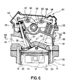
- the engine 18 includes a cylinder block 29 which may be considered to be conventional and which has a cylinder bore 31 in which a piston 32 is supported for reciprocation.
- the cylinder bore 31 is provided by a cylinder liner 33 that is pressed or otherwise secured into the cylinder block assembly 29 and specifically a main casting 34 thereof.
- the piston 32 drives a crankshaft (not shown) in a known manner.
- a cylinder head is affixed to the cylinder block 29 and is formed with a lower sealing surface which surrounds a combustion chamber recess 36 and that is adapted to be affixed in sealing relationship to the upper surface of the cylinder block 29 with an interposed gasket (not shown).
- the piston 32 and specifically its head and the cylinder bore 13 form with the cylinder head combustion chamber recess a chamber, the volume of which cyclically varies during the reciprocation of the piston 32 as is well known.
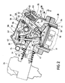
- the engine 18 is provided with an induction system that comprises a first pair of intake valves 37 which are supported for reciprocation about parallel axes within valve guides pressed into the cylinder head 35.
- the axes of reciprocation of the first pair of intake valves 37 is disposed at an acute angle to a plane perpendicular to the plane of Figure 2 and containing the axis of the cylinder bore 31.
- a third intake valve 38 which also is supported for reciprocation within the cylinder head 35 by means of a pressed in intake valve guides and the intake valve 38 also reciprocates about an acute angle to the aforementioned plane.
- the axis of reciprocation of the intake valve 38 is at a lesser angle than the axes of reciprocation of the intake valves 37 to this plane, as described in United States Letters Patent No. 4,660,529, entitled “Four Cycle Engine”, issued April 28, 1987, and assigned to the assignee of this application.
- Each of the intake valves 37 and 38 is urged toward its closed position by means of a coil spring assemblage 39 which bears against a respective pad 41 engaged with a surface of the cylinder head 35 and a retainer 42 that is affixed by means of a keeper assembly to the upper end of the stem of the respective intake valve.
- the valves 37 and 38 are opened in a manner which will be described.
- the intake valves 37 and 38 control the flow of a fuel/air charge, formed by the carburetors 24, through an induction passage 43 that is formed in one side of the cylinder head assembly 35 and which terminates in valve seats 44 associated with the pair of intake valves 37 and a valve seat 45 associated with the remaining intake valve 38.
- the valve seats 44 and 45 may be suitably pressed within the cylinder head 35 in a known manner.
- the induction passage 43 forms a single opening 46 in the intake side of the cylinder head 35 and a manifold section 47 is affixed to this intake side.
- the manifold section 47 includes two intake openings 48 which are separated by a dividing portion 49 that has a generally triangular shape configuration so as to merge the two intake openings 48 gradually into a single opening at the cylinder head opening 46.
- This permits the use of two carburetors 24 that are affixed to the manifold 47 for delivering adequate fuel/air charge to the three intake valves 37 and 38.
- Other forms of charge forming systems including fuel injection systems may be utilized in conjunction with the invention.
- the cylinder head 35 also supports a pair of exhaust valves 51 that are disposed generally on the opposite side of the aforenoted plane and which have stem portions that are reciprocally supported within the cylinder head 35 about parallel axes.
- the axis of reciprocation of the exhaust valves 51 is at an acute angle to the aforenoted plane and this angle is greater than the angle of reciprocation of the single intake valve 38 and lesser than the angle of reciprocation of the pair of exhaust valves 37, as noted in aforenoted United States Letters Patent No. 4,660,529.
- the exhaust valves 51 are urged to their closed position by means of coil compression springs 52 that are loaded in a manner similar to the springs 35 of the intake valves 37 and 38. These exhaust valves 51 are opened in a manner which will be described.
- the exhaust valves 51 control the flow of exhaust gases through a pair of respective exhaust ports 53 that extend through the opposite side of the cylinder head from the intake port 41.
- the exhaust ports 53 originate at respective valve seats 54 that cooperate with each of the exhaust valves 51 in a known manner to control the flow of exhaust gases from the combustion chamber 37 into the exhaust ports 53.
- the exhaust ports 53 diverge generally from a plane that is perpendicular to the aforenoted plane and which is parallel to the plane of Figure 2 so that the engine can clear the single down pipe 22 of the frame assembly as clearly shown in Figure 5. In this way, the engine can have adequate breathing capability and a relatively simple construction.
- the intake valves 37 and 38 and exhaust valves 51 are all operated by means of a single overhead camshaft 55 that is journaled on the cylinder head assembly 35 for rotation about a camshaft axis that extends generally parallel to the aforementioned plane passing through the cylinder bore axis and perpendicular to the plane of Figure 2.
- the camshaft axis is, however, offset toward the intake valves 37 and 38 and the intake valves 37 and 38 lie substantially on one side of a plane parallel to the aforenoted plane and containing the axis of rotation of the camshaft 55 while the exhaust valves 51 lie on the other side of this plane.
- camshaft 55 The manner of support for the camshaft 55 is described in my copending application entitled “Camshaft Arrangement For Multi-Valve Engine", Serial No. , filed and assigned to the assignee of this application (Attorney Docket No. 2503-01341) or my copending application entitled “Combustion Chamber And Valve Operating Mechanism For Multi-Valve Engine”, Serial No. , filed , and also assigned to the assignee of this application (Attorney Docket No. 2503-01340). Since the manner of driving and supporting the camshaft 55 is not necessary to understand the construction and operation of this invention, the disclosures of those copending applications are incorporated herein by reference and will not be described again in connection with this application. It should be noted, however, that the camshaft 55 is positioned generally above an arcuately configured upper wall of the cylinder head assembly 35.
- the bearing assembly for the camshaft 55 includes a cam cover and bearing cap assembly, indicated generally by the referernce numeral 56 and which pivotally supports rocker arm assemblies 57 and 58 in the manner described in the aforenoted copending applications, for example, by rocker arm shafts 60, for operating the intake valves 37 and 38 and exhaust valves 51, respectively.
- the number of rocker arms employed for this purpose can be varied and since the rocker arm and valve operating mechanism forms no part of the invention, these features are not believed to be necessary to understand the construction and operation of the embodiment of the invention.
- a single camshaft 55 for operating all of the valves 37 and 38 and 51 simplifies the overall construction.
- the central positioning of the camshaft 55 makes it difficult, with conventional constructions, to position the spark plug for the engine at the center of the combustion chamber 37.
- a spark plug well 59 consisting of aligned bores 61 and 62 formed in the cam cover 56 and cylinder head 35, respectively, to pass a spark plug 63.
- the cylinder head is formed with a tapped spark plug receiving opening 64 in which the spark plug 63 is received so that its gap is disposed substantially at the center of the combustion chamber 37 as may be best seen in Figure 4. This permits good flame propagation and insures complete combustion under all running conditions.
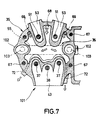
- the cylinder head 35 is provided with a very large capacity cooling jacket 65 which is configured as best shown in Figures 2 and 3, so as to substantially surround the spark plug well 59 and also to extend substantially in part around the portions of the cylinder head that reciprocally support the stems of the intake valves 37 and 38 and the exhaust valves 51 as clearly shown in Figure 3.
- the cooling jacket 65 extends around greater than 180° of the bearing area of the respective valve stems so as to insure good and adequate cooling for them.
- the cooling jacket 65 extends between the cylinder head surface below the camshaft 55 and a lower surface 66 thereof which is adjacent the combustion chamber wall 37 so as to insure good cooling.
- the cylinder head 35 is affixed to the cylinder block 29 by means of a plurality of studs 67 and these studs are disposed at the corners of the combustion chamber 36 but outwardly of the area where the valves 37, 38 and 51 are supported so as to not interfere with the volume of the cooling jacket 65.
- coolant is delivered to the cooling jacket 65 in proximity to the portions of the cylinder head that support the exhaust valves 51 (the more highly heated valves) by means of a first inlet 68 that is disposed in the recess between the portion of the cylinder head that journals the exhaust valves 51 and a pair of outer inlets 69 that are each disposed between the cylinder head studs 67 and the cylinder head portion that journals the outer side of the exhaust valves 51. Water is delivered to these inlets 68 and 69 from a cooling jacket 71 of the cylinder block 29.
- the coolant then flows in the direction of the arrows shown in Figure 3 from the inlets 68 and 69 across the cooling jacket 65 toward a pair of spaced outlets 72 that are disposed outwardly of the portion of the cylinder head where the intake valve stems 37 are supported and the adjacent cylinder head studs 67.
- the hotter exhaust valves will be heated first and then the cooler intake valves will be cooled.
- Coolant is discharged from the cooling jacket 65 and specifically the outlets 72 to a water manifold 73 that extends across the rearward portion of the cylinder head 35 from a first exit port 74 that communicates with one of the passages 72 and a cross passage 75 which then is intersected by a passage 77 exiting from the other cylinder head outlet 72 for return to the radiator 30 for cooling.
- this circulation is effected by a suitable pressure pump (not shown) and thermostat.
- the engine has been provided with a single spark plug for the combustion chamber.
- a pair of spark plug wells 102 that are formed on diametrically opposite sides of the cylinder head 102 and in a plane that extends generally parallel to the plane aforenoted containing the cylinder bore axis and, in fact, may be coincident with it.
- a pair of spark plugs 103 are received, one in each of these wells and have their gaps disposed in the combustion chamber as best shown in Figure 8 wherein the spark plug gaps are disposed so that the flame travel from them will encompass the entire combustion chamber under all running conditions so as to insure complete combustion.
- spark plug wells 102 are disposed out of the center of the cooling jacket 65 but nevertheless protrude substantially into it in the area of the inlets 69 and outlets 72 so as to insure adequate cooling in this area.
Landscapes
- Engineering & Computer Science (AREA)
- Chemical & Material Sciences (AREA)
- Combustion & Propulsion (AREA)
- Mechanical Engineering (AREA)
- General Engineering & Computer Science (AREA)
- Cylinder Crankcases Of Internal Combustion Engines (AREA)
Priority Applications (1)
| Application Number | Priority Date | Filing Date | Title |
|---|---|---|---|
| DE1989612591 DE68912591T2 (de) | 1989-10-12 | 1989-10-12 | Zylinderkopfkühlung für eine Mehrventil-Brennkraftmaschine. |
Applications Claiming Priority (1)
| Application Number | Priority Date | Filing Date | Title |
|---|---|---|---|
| JP63134053A JP2575807B2 (ja) | 1988-05-30 | 1988-05-30 | 4サイクルエンジンのシリンダヘッド冷却構造 |
Publications (2)
| Publication Number | Publication Date |
|---|---|
| EP0422276A1 true EP0422276A1 (de) | 1991-04-17 |
| EP0422276B1 EP0422276B1 (de) | 1994-01-19 |
Family
ID=15119263
Family Applications (1)
| Application Number | Title | Priority Date | Filing Date |
|---|---|---|---|
| EP89119003A Expired - Lifetime EP0422276B1 (de) | 1988-05-30 | 1989-10-12 | Zylinderkopfkühlung für eine Mehrventil-Brennkraftmaschine |
Country Status (3)
| Country | Link |
|---|---|
| US (1) | US4972807A (de) |
| EP (1) | EP0422276B1 (de) |
| JP (1) | JP2575807B2 (de) |
Cited By (2)
| Publication number | Priority date | Publication date | Assignee | Title |
|---|---|---|---|---|
| EP0744542A1 (de) * | 1995-05-22 | 1996-11-27 | Dr.Ing.h.c. F. Porsche Aktiengesellschaft | Zylinderkopf für eine wassergekühlte, mehrzylindrige Brennkraftmaschine |
| FR2774128A1 (fr) * | 1998-01-23 | 1999-07-30 | Renault | Culasse de moteur a combustion interne refroidie par liquide |
Families Citing this family (19)
| Publication number | Priority date | Publication date | Assignee | Title |
|---|---|---|---|---|
| JP2815066B2 (ja) * | 1989-12-11 | 1998-10-27 | ヤマハ発動機株式会社 | 4サイクルエンジンの冷却構造 |
| JP3150353B2 (ja) * | 1991-03-18 | 2001-03-26 | マツダ株式会社 | エンジンの燃焼室構造 |
| EP0778403B1 (de) * | 1995-03-28 | 2000-11-08 | Mitsubishi Jidosha Kogyo Kabushiki Kaisha | Brennkraftmaschine mit direkteinspritzung |
| JPH0988583A (ja) * | 1995-09-22 | 1997-03-31 | Yamaha Motor Co Ltd | 小型水上走行艇用エンジン |
| JPH116430A (ja) * | 1997-06-18 | 1999-01-12 | Yamaha Motor Co Ltd | 水冷多気筒エンジン |
| JP3883025B2 (ja) | 1998-03-26 | 2007-02-21 | ヤマハマリン株式会社 | 筒内燃料噴射式エンジン |
| AU2001243304A1 (en) | 2000-02-29 | 2001-09-12 | Bombardier Inc. | Four stroke engine having blow-by ventilation system and lubrication system |
| JP4485647B2 (ja) | 2000-04-19 | 2010-06-23 | ヤマハ発動機株式会社 | 船外機用エンジン |
| JP4357881B2 (ja) | 2003-06-12 | 2009-11-04 | ヤマハ発動機株式会社 | 小型船舶 |
| JP2006002633A (ja) | 2004-06-16 | 2006-01-05 | Yamaha Marine Co Ltd | 水ジェット推進艇 |
| JP2006037730A (ja) | 2004-07-22 | 2006-02-09 | Yamaha Marine Co Ltd | 過給式エンジンの吸気装置 |
| JP2006083713A (ja) | 2004-09-14 | 2006-03-30 | Yamaha Marine Co Ltd | 過給装置の潤滑構造 |
| US7337755B2 (en) * | 2004-09-30 | 2008-03-04 | Honda Motor Co., Ltd. | Cylinder head cooling structure for an internal combustion engine, including an oil temperature sensor and an oil temperature control system |
| JP2007062432A (ja) | 2005-08-29 | 2007-03-15 | Yamaha Marine Co Ltd | 小型滑走艇 |
| JP4614853B2 (ja) | 2005-09-26 | 2011-01-19 | ヤマハ発動機株式会社 | 過給機の取付構造 |
| JP4717586B2 (ja) * | 2005-10-24 | 2011-07-06 | 川崎重工業株式会社 | 燃料噴射式エンジン、及びこれを備える自動二輪車 |
| US8539929B2 (en) * | 2009-11-18 | 2013-09-24 | Harley-Davidson Motor Company | Cylinder head cooling system |
| JP5479965B2 (ja) * | 2010-03-23 | 2014-04-23 | 本田技研工業株式会社 | 車両用エンジンにおける点火プラグ冷却装置 |
| CN113236434A (zh) * | 2021-04-27 | 2021-08-10 | 重庆隆鑫机车有限公司 | 冷却水套及发动机 |
Citations (3)
| Publication number | Priority date | Publication date | Assignee | Title |
|---|---|---|---|---|
| GB1083951A (en) * | 1965-01-05 | 1967-09-20 | Motoren Werke Mannheim Ag | A cylinder for a water-cooled internal combustion engine, more especially a diesel engine having separate cylinder heads |
| DE3543443A1 (de) * | 1984-12-10 | 1986-06-12 | Mazda Motor Corp., Hiroshima | Fremdgezuendete brennkraftmaschine |
| EP0144179B1 (de) * | 1983-11-25 | 1988-02-10 | Honda Giken Kogyo Kabushiki Kaisha | Mehrventilbrennkraftmaschine |
Family Cites Families (2)
| Publication number | Priority date | Publication date | Assignee | Title |
|---|---|---|---|---|
| NL78718C (de) * | 1950-09-09 | |||
| US4635591A (en) * | 1984-10-11 | 1987-01-13 | Hledin Alexander S | Internal-combustion engines |
-
1988
- 1988-05-30 JP JP63134053A patent/JP2575807B2/ja not_active Expired - Fee Related
-
1989
- 1989-05-26 US US07/357,473 patent/US4972807A/en not_active Ceased
- 1989-10-12 EP EP89119003A patent/EP0422276B1/de not_active Expired - Lifetime
Patent Citations (3)
| Publication number | Priority date | Publication date | Assignee | Title |
|---|---|---|---|---|
| GB1083951A (en) * | 1965-01-05 | 1967-09-20 | Motoren Werke Mannheim Ag | A cylinder for a water-cooled internal combustion engine, more especially a diesel engine having separate cylinder heads |
| EP0144179B1 (de) * | 1983-11-25 | 1988-02-10 | Honda Giken Kogyo Kabushiki Kaisha | Mehrventilbrennkraftmaschine |
| DE3543443A1 (de) * | 1984-12-10 | 1986-06-12 | Mazda Motor Corp., Hiroshima | Fremdgezuendete brennkraftmaschine |
Cited By (2)
| Publication number | Priority date | Publication date | Assignee | Title |
|---|---|---|---|---|
| EP0744542A1 (de) * | 1995-05-22 | 1996-11-27 | Dr.Ing.h.c. F. Porsche Aktiengesellschaft | Zylinderkopf für eine wassergekühlte, mehrzylindrige Brennkraftmaschine |
| FR2774128A1 (fr) * | 1998-01-23 | 1999-07-30 | Renault | Culasse de moteur a combustion interne refroidie par liquide |
Also Published As
| Publication number | Publication date |
|---|---|
| EP0422276B1 (de) | 1994-01-19 |
| US4972807A (en) | 1990-11-27 |
| JP2575807B2 (ja) | 1997-01-29 |
| JPH01301947A (ja) | 1989-12-06 |
Similar Documents
| Publication | Publication Date | Title |
|---|---|---|
| US4972807A (en) | Cylinder head cooling for multiple valve engine | |
| EP1722090B1 (de) | Mehrzylinderkopf | |
| JP4119023B2 (ja) | エンジンにおけるブリーザ装置 | |
| JP4093512B2 (ja) | エンジンの排気用二次空気供給装置 | |
| USRE34226E (en) | Cylinder head cooling for multiple valve engine | |
| JP3881796B2 (ja) | エンジンの冷却装置 | |
| US4971008A (en) | Porting arrangement for multi-valve engine | |
| US5127380A (en) | Combustion chamber and valve operating mechanism for multi-valve engine | |
| JP3706809B2 (ja) | 多気筒エンジン | |
| JP3875417B2 (ja) | 車両用エンジンにおける燃料噴射装置 | |
| US5081960A (en) | Cooling arrangement for multi-valve engine | |
| JP2000161129A (ja) | 多気筒エンジンのシリンダヘッド構造 | |
| JP3777236B2 (ja) | 水冷エンジン | |
| US4979474A (en) | Camshaft arrangement for multi valve engine | |
| JP3824832B2 (ja) | 内燃機関のシリンダヘッド | |
| US4864981A (en) | Overhead valve type engine | |
| US4069796A (en) | Engine manifold with air gap insulator carburetor mounting | |
| EP0682176B1 (de) | Brennkraftmaschine | |
| JP4363686B2 (ja) | エンジンの冷却装置 | |
| EP0422277A1 (de) | Brennkammer und Ventilsteuervorrichtung für Mehrventil-Brennkraftmaschine | |
| JPH07139421A (ja) | 油冷エンジンのオイル通路構造 | |
| JP3699312B2 (ja) | 筒内燃料噴射型内燃機関の構造 | |
| US4520627A (en) | Turbocharged internal combustion engine | |
| JP4057725B2 (ja) | 自動二輪車用水平対向型4サイクルエンジン | |
| EP0430258B1 (de) | Kühlsystem für eine Brennkraftmaschine mit mehreren Ventilen |
Legal Events
| Date | Code | Title | Description |
|---|---|---|---|
| PUAI | Public reference made under article 153(3) epc to a published international application that has entered the european phase |
Free format text: ORIGINAL CODE: 0009012 |
|
| 17P | Request for examination filed |
Effective date: 19901224 |
|
| AK | Designated contracting states |
Kind code of ref document: A1 Designated state(s): DE ES FR GB IT |
|
| 17Q | First examination report despatched |
Effective date: 19910731 |
|
| GRAA | (expected) grant |
Free format text: ORIGINAL CODE: 0009210 |
|
| AK | Designated contracting states |
Kind code of ref document: B1 Designated state(s): DE ES FR GB IT |
|
| REF | Corresponds to: |
Ref document number: 68912591 Country of ref document: DE Date of ref document: 19940303 |
|
| ITF | It: translation for a ep patent filed | ||
| PG25 | Lapsed in a contracting state [announced via postgrant information from national office to epo] |
Ref country code: ES Free format text: LAPSE BECAUSE OF FAILURE TO SUBMIT A TRANSLATION OF THE DESCRIPTION OR TO PAY THE FEE WITHIN THE PRESCRIBED TIME-LIMIT Effective date: 19940430 |
|
| ET | Fr: translation filed | ||
| PLBE | No opposition filed within time limit |
Free format text: ORIGINAL CODE: 0009261 |
|
| STAA | Information on the status of an ep patent application or granted ep patent |
Free format text: STATUS: NO OPPOSITION FILED WITHIN TIME LIMIT |
|
| 26N | No opposition filed | ||
| PGFP | Annual fee paid to national office [announced via postgrant information from national office to epo] |
Ref country code: ES Payment date: 19971017 Year of fee payment: 9 |
|
| REG | Reference to a national code |
Ref country code: GB Ref legal event code: IF02 |
|
| PGFP | Annual fee paid to national office [announced via postgrant information from national office to epo] |
Ref country code: DE Payment date: 20081014 Year of fee payment: 20 |
|
| PGFP | Annual fee paid to national office [announced via postgrant information from national office to epo] |
Ref country code: IT Payment date: 20081028 Year of fee payment: 20 |
|
| PGFP | Annual fee paid to national office [announced via postgrant information from national office to epo] |
Ref country code: FR Payment date: 20081014 Year of fee payment: 20 |
|
| PGFP | Annual fee paid to national office [announced via postgrant information from national office to epo] |
Ref country code: GB Payment date: 20081008 Year of fee payment: 20 |
|
| REG | Reference to a national code |
Ref country code: GB Ref legal event code: PE20 Expiry date: 20091011 |
|
| PG25 | Lapsed in a contracting state [announced via postgrant information from national office to epo] |
Ref country code: GB Free format text: LAPSE BECAUSE OF EXPIRATION OF PROTECTION Effective date: 20091011 |