EP0422285A2 - Télescope - Google Patents
Télescope Download PDFInfo
- Publication number
- EP0422285A2 EP0422285A2 EP89120421A EP89120421A EP0422285A2 EP 0422285 A2 EP0422285 A2 EP 0422285A2 EP 89120421 A EP89120421 A EP 89120421A EP 89120421 A EP89120421 A EP 89120421A EP 0422285 A2 EP0422285 A2 EP 0422285A2
- Authority
- EP
- European Patent Office
- Prior art keywords
- ring
- binoculars
- focus
- knurled
- guide pin
- Prior art date
- Legal status (The legal status is an assumption and is not a legal conclusion. Google has not performed a legal analysis and makes no representation as to the accuracy of the status listed.)
- Withdrawn
Links
Images
Classifications
-
- G—PHYSICS
- G02—OPTICS
- G02B—OPTICAL ELEMENTS, SYSTEMS OR APPARATUS
- G02B7/00—Mountings, adjusting means, or light-tight connections, for optical elements
- G02B7/02—Mountings, adjusting means, or light-tight connections, for optical elements for lenses
- G02B7/12—Adjusting pupillary distance of binocular pairs
-
- G—PHYSICS
- G02—OPTICS
- G02B—OPTICAL ELEMENTS, SYSTEMS OR APPARATUS
- G02B23/00—Telescopes, e.g. binoculars; Periscopes; Instruments for viewing the inside of hollow bodies; Viewfinders; Optical aiming or sighting devices
- G02B23/16—Housings; Caps; Mountings; Supports, e.g. with counterweight
- G02B23/18—Housings; Caps; Mountings; Supports, e.g. with counterweight for binocular arrangements
Definitions
- the invention relates to binoculars according to the preamble of claim 1.
- the binoculars according to the invention are a binocular.
- the bridge connecting the two eyepieces can be set to a fixed eye relief. However, it is preferably designed as an articulated bridge for individual adjustment to the user's eye relief.
- the normal focus for spectacle wearers and people with normal vision can be achieved through the eyepiece pulls with the help of the central drive.
- one or both eyepieces can be provided with a diopter adjustment.
- the binoculars according to the invention can therefore be largely adapted to the different requirements of the market.
- the central drive of the binoculars according to the invention is conventional and therefore practical.
- the knurled body can be designed as a knurled wheel, screw or roller. Knurling rollers are known to be in the bridge below brought, while knurled wheels or disks can also be arranged above or below the bridge. Through these possible embodiments of the invention, it can be adapted to different claims.
- the invention is based on known binoculars which have the described central drive and make use of the diopter adjustment.
- the center drive can also be realized with a focus rocker.
- the advantage of these glasses is that they can be individually adjusted to the eyes of each user. As is known, this happens in such a way that the binoculars are adjusted to a certain long distance, taking into account the depth of field, which e.g. Is 150 m.
- the diopter setting is made by the user, who generally turns a diopter ring on one or both eyepieces. Once the setting has been made, each focus area can be adjusted by turning the central drive without the user having to put on his glasses.
- binoculars with easier adjustment uses a single eyepiece adjustment.
- the focus is adjusted by turning the left or right diopter ring, which is also used to set the distance.
- the disadvantage of such binoculars is that the focus range once set can only be changed by adjusting each of the two eyepieces. This extends the time required to change the focus area. In practice, the difficulty arises that the setting of the binoculars often takes too long.
- Another attempt to make it easier for the user to focus the binoculars is to provide the binoculars with a fix focus setting. With these binoculars, the optics of the binoculars are fixed at approx. 70 to 80 m. It is therefore not possible to change the sharpness. Such binoculars can be used by people with normal vision who have 100% vision Bring it with both eyes or with glasses wearers who use their glasses without any adjustment, although only objects in the focus range of approx. 14 m to 80 m appear sharp. The disadvantage is that due to the fixed setting of the focus area to approx. 80 m, the observation in the infinity area does not result in perfect detail sharpness and is based on the ability to accommodate the eyes.
- the invention has for its object to provide a pair of binoculars, which hardly allows adjustment errors of the user in a simple manner and largely eliminates the disadvantages described.
- the binoculars described at the beginning which has a central drive serving for focusing at all distances, are provided with a further knurled ring and a stop ring, whereby two further setting options are created which allow a fix focus setting, but the disadvantage of which is due to a dual -Focus setting is to be avoided.
- This dual focus setting enables a fixed focus setting to a close range, which can be, for example, about 6 m to 14 m and to a far range, which can be set to about 14 m to infinity. Since the basic structure of the binoculars, as initially assumed to be known, is not changed by the invention, the glass can be handled by both normal-sighted and defective users who use the glass with or without a visual aid.
- the invention has the advantage that the binoculars can be used for all areas immediately by using the dual focus setting, with only a change of the drive being required when changing over to the fixed focus of the near area or to the fixed focus of the far area is.
- the binoculars according to the invention can be used like conventional binoculars with adjustment to everyone any focus range can be used. Inexperienced users can largely avoid errors by using the dual focus setting. Experts can use the binoculars according to the invention as usual, but can also take advantage of a fixed focus setting. They consist of the fact that the user can adjust the binoculars to objects in different focus levels much faster.
- the invention is preferably implemented with the features of claim 2. This results in a simple structure of the fix focus setting for each focus area and an easy-to-use conversion of the binoculars according to the invention to the conventional normal setting.
- the invention combines in claim 3 the fix focus setting described with the stop ring, whereby a further simplified construction is achieved.
- the described additional setting options of the binoculars according to the invention should be able to be operated without error, even if the user holds the binoculars in front of the eyes.
- a practical embodiment of this possibility allow the features of claim 4.
- the two additional adjustment options offered by the binoculars according to the invention are arranged in an axial extension of the normal setting.
- the features of claim 5 represent an embodiment of the invention in which a precise working of the stop ring is guaranteed. This is done by dividing the stop onto several ring surfaces that come into mutual contact.
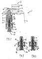
- the binoculars are prismatic lenses in which the distance between the lenses (not shown) is greater than the distance between the eyepieces, but of which only one eyepiece is drawn at (2).
- the prism housing (3) is used to guide the focuser (4).
- the two focusers are connected to each other by an articulated bridge (5).
- a central drive (6) is provided in the optical central axis, which is arranged between two bridge hinges (7, 8) which connect the two prism housings to one another.
- the central drive has two moving parts, namely a knurled roller (9) and a guide pin (10). These parts are supplemented by a fixed tube (11).
- a guide pin (12) runs in a spiral guide groove (13) which is cut into the inner cylinder of the knurled roller (9). Due to the multi-part fixation by the fixation of the guide pin (10) to the bridge (5) shown in (14), the two eyepiece pulls (4) are actuated simultaneously in one of the two directions.
- the binoculars (1) have a fix focus adjustability by means of the central drive (6) and a knurled ring (15), which can be fixed. This enables a dual focus setting, which is ensured by an axially adjustable stop ring (16).
- the guide pin (10) with an axis (17) is extended, which is rotatably fixed at (18) in the end face of the guide pin.
- the extension axis (17) penetrates a flange screw (19), which is supported on the lower hinge straps (8) and is screwed into the lower end of the tube (11).
- a socket (20) sits on the flange screw (19) and receives the inner flange of a clamping ring (21) in an outer groove.
- the clamping ring has inwardly directed clamping jaws (22) and an external thread on its upper cylindrical part, onto which an internal thread of the knurled ring (15) is turned.
- the clamping jaws (22) are released as soon as the knurled ring (15) is in its upper, that is, the hinge straps (8) approximate position.
- the clamping jaws are closed as soon as the lower position of the clamping ring shown in FIGS. 1 and 12 is reached.
- the axis (17) used to extend the pin (10) is provided with a cylindrical flange (23). It has a threaded spindle (24) at its free end.
- the stop ring is pierced with a cylindrical bore (26) which is normally closed with a cover plate (27).
- a grub screw (28) with a head (29) sits under the cover sheet (27). It is screwed into the free end of the axle (17).
- the clamping jaws (22) of the knurled ring (15) act on a fixed tube (29) (Fig. 2) which between the lower ring surface of the stop ring (16) and the inner annular end surface (31) of a recess (32) of the fixed tube (15 ) and the annular surface of the flange (23) can be clamped.
- the pin (24) of the stop ring (16) is seated in the recess (32).
- the knurled ring (15) is first turned so that the jaws (22) release the fixed tube (30). With the normally provided right-hand thread, this is done by turning the knurled ring (15) to the left.
- the knurled stop screw (16) is then brought into the position according to FIG. 2, that is to say rotated to the right in the case of the right-hand thread that is usually provided, until the stop surfaces described lie on one another.
- the tube (30) is thereby fixed.
- the user now targets an object at a distance of approx. 150 m and adjusts the focus by turning the central drive (6).
- the knurled ring (15) is tightened so that the clamping jaws (22) grip the tube (30). This is done by turning to the right.
- the parts assume their position shown in FIG. 2.
- the binoculars (1) are then in the fixed focus setting, ie the focus is fixed, to a focus range of approximately 15 m to infinity.
- the following dual focus setting presupposes the position of the described parts according to FIG. 3. To do this, turn the stop ring (16) to the left as far as it will go, i.e. until the pin (32) of the stop ring (16) on the lower ring surface of the head (29) of the grub screw (28) is supported. If the user now turns the central drive to the right as far as it will go, he is in the far range. Conversely, the rotation of the central drive (6) leads to the left in the close range up to the stop. 3 is the usual setting for the use of binoculars (1).
- the binoculars according to the invention are provided with a diopter ring (33), as a result of which they can be adjusted to users who normally need a visual aid but do not want to use them when using the binoculars.
Landscapes
- Physics & Mathematics (AREA)
- General Physics & Mathematics (AREA)
- Optics & Photonics (AREA)
- Astronomy & Astrophysics (AREA)
- Telescopes (AREA)
Priority Applications (2)
| Application Number | Priority Date | Filing Date | Title |
|---|---|---|---|
| JP3263190A JPH03126905A (ja) | 1989-10-10 | 1990-02-15 | 望遠鏡 |
| CA 2024483 CA2024483A1 (fr) | 1989-10-10 | 1990-08-31 | Jumelles |
Applications Claiming Priority (2)
| Application Number | Priority Date | Filing Date | Title |
|---|---|---|---|
| DE19893933793 DE3933793A1 (de) | 1989-10-10 | 1989-10-10 | Fernglas |
| DE3933793 | 1989-10-10 |
Publications (2)
| Publication Number | Publication Date |
|---|---|
| EP0422285A2 true EP0422285A2 (fr) | 1991-04-17 |
| EP0422285A3 EP0422285A3 (en) | 1991-07-17 |
Family
ID=6391180
Family Applications (1)
| Application Number | Title | Priority Date | Filing Date |
|---|---|---|---|
| EP19890120421 Withdrawn EP0422285A3 (en) | 1989-10-10 | 1989-11-04 | Telescope |
Country Status (2)
| Country | Link |
|---|---|
| EP (1) | EP0422285A3 (fr) |
| DE (1) | DE3933793A1 (fr) |
Family Cites Families (5)
| Publication number | Priority date | Publication date | Assignee | Title |
|---|---|---|---|---|
| DE301184C (fr) * | ||||
| DE48806C (de) * | E. T. DE WOGAN in Paris 179 Boulevard Pereire; Vertreter-. J. BRANDT & G. W. V. NAWROCKI in Berlin W., Friedrichstrafse 78 | Operngucker oder Doppel-Fernrohr mit Schnelleinstellung | ||
| DE2531053A1 (de) * | 1975-07-11 | 1977-01-27 | Harald Westphal | Bildschaerfeeinstellung beim fernrohr mittels einer feder |
| DE2920583C2 (de) * | 1979-05-21 | 1986-11-06 | Ernst Leitz Wetzlar Gmbh, 6330 Wetzlar | Binokulares Fernrohr mit Innenfokussierung |
| US4848887A (en) * | 1987-11-03 | 1989-07-18 | Jason Empire, Inc. | Fixed focus binoculars |
-
1989
- 1989-10-10 DE DE19893933793 patent/DE3933793A1/de active Granted
- 1989-11-04 EP EP19890120421 patent/EP0422285A3/de not_active Withdrawn
Also Published As
| Publication number | Publication date |
|---|---|
| DE3933793C2 (fr) | 1992-02-27 |
| DE3933793A1 (de) | 1991-04-18 |
| EP0422285A3 (en) | 1991-07-17 |
Similar Documents
| Publication | Publication Date | Title |
|---|---|---|
| DE3109668C2 (fr) | ||
| DE69216763T2 (de) | Feldstecher mit Einzelfokussierung | |
| DE4244161A1 (en) | Automatic focus field glasses - have lens which can be moved in direction of optical axis for sharp adjustment and lenses movable along optical axis for varying refractory force | |
| WO2008135006A1 (fr) | Longue-vue binoculaire | |
| DE1276363B (de) | Binokulare Lupenbrille | |
| EP1598690B1 (fr) | Dispositif de focalisation avec ajustage de dioptre pour téléscopes binoculaires | |
| DE4033151C2 (de) | Binokulares Fernglas | |
| EP0934548B1 (fr) | Lunette grossissante telescopique binoculaire | |
| DE2948421C2 (de) | Doppelfernrohr mit einer zweigelenkigen Verbindungsbrücke | |
| EP3822682B1 (fr) | Lunette et dispositif de mise au point | |
| EP3822683B1 (fr) | Dispositif de mise au point de lunette et limitation de rotation | |
| EP0140836A2 (fr) | Appareil optique pour engendrer une image visuelle stéréoscopique | |
| DE2326088A1 (de) | Fernglas | |
| DE10054137A1 (de) | Fokussiervorrichtung für ein Doppelfernrohr | |
| DE3933793C2 (fr) | ||
| DE2841611B2 (de) | Feldstecher | |
| DE2346758B2 (de) | Aufnahmeobjektiv mit veränderbarer Brennweite | |
| DE19750617B4 (de) | Spezialzange | |
| DE3530649C2 (fr) | ||
| DE2717573A1 (de) | Prismenfeldstecher mit zentralen knoepfen fuer die scharfeinstellung | |
| DE1919248C3 (de) | Vorrichtung zum Einspannen eines optischen Glases auf der Spindel einer Maschine zum Beschneiden des Glasrandes | |
| EP1491937B1 (fr) | Lunettes télescopiques/loupes | |
| DE935885C (de) | Einrichtung zur Scharfeinstellung einer Aufnahmekamera | |
| DE9111404U1 (de) | Okularring für Ferngläser | |
| DE102010025136A1 (de) | Binokulares Fernrohr |
Legal Events
| Date | Code | Title | Description |
|---|---|---|---|
| PUAI | Public reference made under article 153(3) epc to a published international application that has entered the european phase |
Free format text: ORIGINAL CODE: 0009012 |
|
| AK | Designated contracting states |
Kind code of ref document: A2 Designated state(s): DE FR GB IT |
|
| PUAL | Search report despatched |
Free format text: ORIGINAL CODE: 0009013 |
|
| AK | Designated contracting states |
Kind code of ref document: A3 Designated state(s): DE FR GB IT |
|
| 17P | Request for examination filed |
Effective date: 19910704 |
|
| 17Q | First examination report despatched |
Effective date: 19930810 |
|
| STAA | Information on the status of an ep patent application or granted ep patent |
Free format text: STATUS: THE APPLICATION IS DEEMED TO BE WITHDRAWN |
|
| 18D | Application deemed to be withdrawn |
Effective date: 19940601 |