EP0422317A1 - Dispositif de détection d'un courant de fluide dans une conduite - Google Patents
Dispositif de détection d'un courant de fluide dans une conduite Download PDFInfo
- Publication number
- EP0422317A1 EP0422317A1 EP90100388A EP90100388A EP0422317A1 EP 0422317 A1 EP0422317 A1 EP 0422317A1 EP 90100388 A EP90100388 A EP 90100388A EP 90100388 A EP90100388 A EP 90100388A EP 0422317 A1 EP0422317 A1 EP 0422317A1
- Authority
- EP
- European Patent Office
- Prior art keywords
- flow
- line
- fluid
- arrangement
- section
- Prior art date
- Legal status (The legal status is an assumption and is not a legal conclusion. Google has not performed a legal analysis and makes no representation as to the accuracy of the status listed.)
- Withdrawn
Links
- 239000012530 fluid Substances 0.000 title claims abstract description 41
- 239000003570 air Substances 0.000 description 10
- 239000007789 gas Substances 0.000 description 6
- 238000011156 evaluation Methods 0.000 description 3
- 238000004519 manufacturing process Methods 0.000 description 3
- 238000004868 gas analysis Methods 0.000 description 2
- 239000007788 liquid Substances 0.000 description 2
- 238000005259 measurement Methods 0.000 description 2
- 239000000203 mixture Substances 0.000 description 2
- 230000006978 adaptation Effects 0.000 description 1
- 238000004026 adhesive bonding Methods 0.000 description 1
- 239000012080 ambient air Substances 0.000 description 1
- 238000004458 analytical method Methods 0.000 description 1
- 238000009530 blood pressure measurement Methods 0.000 description 1
- 238000011109 contamination Methods 0.000 description 1
- 238000013461 design Methods 0.000 description 1
- 238000010586 diagram Methods 0.000 description 1
- 238000009826 distribution Methods 0.000 description 1
- 238000005553 drilling Methods 0.000 description 1
- 230000007613 environmental effect Effects 0.000 description 1
- 230000001939 inductive effect Effects 0.000 description 1
- 238000009434 installation Methods 0.000 description 1
- 230000003993 interaction Effects 0.000 description 1
- 238000000034 method Methods 0.000 description 1
- 238000002156 mixing Methods 0.000 description 1
- 238000012806 monitoring device Methods 0.000 description 1
- 238000012544 monitoring process Methods 0.000 description 1
- 230000035945 sensitivity Effects 0.000 description 1
- 230000003068 static effect Effects 0.000 description 1
Images

Classifications
-
- G—PHYSICS
- G01—MEASURING; TESTING
- G01F—MEASURING VOLUME, VOLUME FLOW, MASS FLOW OR LIQUID LEVEL; METERING BY VOLUME
- G01F15/00—Details of, or accessories for, apparatus of groups G01F1/00 - G01F13/00 insofar as such details or appliances are not adapted to particular types of such apparatus
-
- G—PHYSICS
- G01—MEASURING; TESTING
- G01F—MEASURING VOLUME, VOLUME FLOW, MASS FLOW OR LIQUID LEVEL; METERING BY VOLUME
- G01F1/00—Measuring the volume flow or mass flow of fluid or fluent solid material wherein the fluid passes through a meter in a continuous flow
- G01F1/68—Measuring the volume flow or mass flow of fluid or fluent solid material wherein the fluid passes through a meter in a continuous flow by using thermal effects
-
- G—PHYSICS
- G01—MEASURING; TESTING
- G01F—MEASURING VOLUME, VOLUME FLOW, MASS FLOW OR LIQUID LEVEL; METERING BY VOLUME
- G01F1/00—Measuring the volume flow or mass flow of fluid or fluent solid material wherein the fluid passes through a meter in a continuous flow
- G01F1/68—Measuring the volume flow or mass flow of fluid or fluent solid material wherein the fluid passes through a meter in a continuous flow by using thermal effects
- G01F1/684—Structural arrangements; Mounting of elements, e.g. in relation to fluid flow
- G01F1/6847—Structural arrangements; Mounting of elements, e.g. in relation to fluid flow where sensing or heating elements are not disturbing the fluid flow, e.g. elements mounted outside the flow duct
-
- G—PHYSICS
- G01—MEASURING; TESTING
- G01F—MEASURING VOLUME, VOLUME FLOW, MASS FLOW OR LIQUID LEVEL; METERING BY VOLUME
- G01F5/00—Measuring a proportion of the volume flow
Definitions
- the innovation relates to a device for determining a fluid flow through a line with an orifice arrangement which generates an effective pressure and which fills at least part of the cross section of the line, and with a flow transmitter which emits an electrical signal corresponding to the fluid flow through the line.
- this device can serve as a flow monitor, which indicates the presence of a gas or liquid flow. Further applications lie in the metrological determination of the volume or quantity flow or the mass flow of a fluid.
- the cross section of the fluid line is narrowed at one point, so that the fluid has a higher pressure before the throat than behind the throat, viewed in the flow direction of the fluid stream.
- the difference between the two pressures is called the differential pressure.
- the constriction is caused by an orifice arrangement that fills part of the cross-section of the line.
- Thin disks are often used as screens, the thickness of which is small compared to the diameter of the line.
- Further known orifice arrangements have the shape of a nozzle, with a narrowing inlet opening for the fluid and with an adjoining funnel-shaped neck piece.
- a well-known nozzle arrangement is the Venturi tube.
- the known devices mostly use as pressure transmitters which measure the differential pressure caused by the orifice arrangement. This is a measure of the flow of fluid through the line.
- the pressure measuring device generates an electrical signal, on the basis of which the current fluid flow through the line can be specified after measurement with fluid flows of known size.
- the flow transmitter In order not to disturb the uniform flow of the fluid - since such disturbances cause vortices and distort the pressure measurement - the flow transmitter is arranged outside the line.
- the differential pressure is fed to the transmitter via specially designed measuring lines which measure the fluid pressure in the inlet and outlet of the orifice arrangement.
- the interaction of measuring lines, flow sensors and orifice arrangement requires a complicated structural design of the known device for Determining the fluid flow, space for parts of the device also being provided outside the line. This leads to disadvantages on the one hand in the production of such a device and on the other hand in the installation of the device in the conduit in confined spaces.
- the aperture arrangement has a plurality of openings which are permeable to the medium, one of which is designed as a measuring opening in which the flow transmitter is arranged.
- the constriction created in the line by the orifice arrangement allows the fluid to flow faster in the area of the orifice, i.e. static pressure energy is converted into dynamic speed energy, the pressure in front of the orifice arrangement, viewed in the direction of the fluid flow, being greater than behind the orifice arrangement.
- This pressure difference leads to equalizing currents.
- the fluid flowing through the orifice arrangement is distributed over the various openings. One of these openings is designed as a measuring opening.
- the flow sensor is arranged in it.
- the fluid flow flowing through the measuring opening depends on the ratio of its flow resistance to the total flow resistance of the orifice arrangement.
- the total resistance in turn depends on the number of openings and their size in relation to the aperture area, which is the cross-section of the line covers.
- the flow resistances corresponding to the openings can be determined from the geometry of the orifice arrangement. It is thus possible to deduce the entire fluid flow in the line from the partial flow flowing through the measuring opening.
- Calibration provides a simple way of determining the fluid flow from the signal from the flow transmitter, without having to make complex geometric calculations.
- a fluid is supplied with a known current and the relationship between flow quantities and the electrical signal of the transmitter is determined in a calibration characteristic. This characteristic curve is then used to determine the flow quantities of a fluid to be measured.
- the geometry of the orifice arrangement By varying the geometry of the orifice arrangement, an adaptation to the sensitivity of the flow sensor can be carried out, the distribution of the fluid flow through the measuring opening being changed to the remaining fluid flow. Furthermore, by changing the orifice geometry, the overall flow resistance caused by the orifice arrangement can be adapted to the particular application, for example reduced or increased.
- the panel arrangement has a very simple structure.
- a cylindrical line for example, it can have the shape of a disk, the diameter of which corresponds to the inside dimension of the line.
- the openings are formed by circular holes.
- the disc can be attached to the inner wall of the line by screws or by gluing. If the fluid line has a rectangular cross section, it may be expedient to also form the diaphragm arrangement in a rectangular shape. The manufacture of such Blending is very simple and can be carried out with little technical effort and thus economically.
- the flow sensor is integrated in the orifice arrangement, no further mechanical parts have to be provided on the outer wall of the line, as is the case e.g. is required in the known device.
- the device according to the invention can also be used under spatially confined environmental conditions, since its space requirement does not exceed the dimensions of the fluid line.
- the known pressure difference measuring devices can be used as flow transmitters, which evaluate the differential pressure caused by the orifice arrangement to determine the fluid flow.
- other encoders can also be used that work according to different measuring principles. For example, temperature sensors, inductive flow sensors, counter wheels, etc. come into question.
- the selection of the appropriate flow transmitter depends on the respective application, for example on the type of fluid, i.e. whether the flow of gases or liquids is to be determined according to the temperature, pressure or viscosity of the fluid.
- the measuring opening is extended in the flow direction of the fluid by an additional line in which the flow transmitter is arranged.
- the diaphragm arrangement forms an obstacle to the fluid flow, which creates flow vortices.
- An originally laminar flow can change into a turbulent flow.
- the flow vortices can the measurement result at Falsify the determination of the flow through the measuring opening.
- the flow vortices in the measuring opening and along the additional line are smoothed and a largely laminar flow is fed to the flow transmitter.
- a device for determining the composition of a gas mixture uses the device according to the innovation.
- An air sample 16 is taken from the ambient air to be monitored via an intake pipe 12.
- the vacuum required for this is generated by a suction pump 29.
- the sucked-in air is filtered through a filter grille 14, which can become clogged in the course of the operating time due to contamination.
- a pipe section 10 is inserted into the intake line 12, which has a plurality of openings 19, 40, 42. One of these openings is as Measuring opening 19 formed, which is extended by an additional line 20.
- the air flow flowing through the additional line 20 is determined by a hot wire flow meter 22, the measured mechanical quantity is converted into an electrical signal, which is output via a line 34 to an evaluation unit 30.
- the line 34 is led from the flow meter 22 through an airtight bushing 23 to the outside.
- the sucked-in air enters a measuring chamber 24, in which a gas detector 26 is arranged, which carries out the gas analysis.
- the result of the analysis is passed on to the evaluation unit 30 as an electrical signal via the line 32.
- the facility works continuously, i.e. the suction motor 29 continuously sucks in air and releases it again to the environment via an outlet opening 28.
- the evaluation unit evaluates the signal emitted by the hot wire flow meter 22 and determines whether there is sufficient air flow for the purpose of gas analysis. If this is interrupted, for example as a result of a blockage of the intake filter 14 or as a result of a failure of the intake pump 29, then it emits an alarm signal since the continuous gas monitoring is no longer guaranteed.
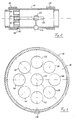
- FIG. 2 shows a longitudinal cross section through part of the intake pipe 12 and the pipe socket 10 according to FIG. 1.
- the panel arrangement 18 is fastened in the pipe socket 10 by a locking screw 38.
- the apertures 19, 40, 42 are beveled in a funnel shape, so that the incoming Air flow is opposed to a low flow resistance and the turbulence of the flow through sharp edges is avoided.
- the hot wire flow meter 22 contains an electrically heated measuring wire, the temperature of which depends on the flow velocity of the air in the additional line 20. The greater this speed, the lower the temperature of the measuring wire with a constant electrical power supply.
- the temperature of the measuring wire can be determined indirectly by its electrical resistance. By evaluating this resistance value, it can be determined whether an air flow is flowing in the pipe section 10 or not.
- FIG. 3 A cross section through the panel arrangement 18 and through the pipe section 10 is shown enlarged in FIG. 3.
- the aperture arrangement 18 fills the entire cross section of the pipe section 10 and has openings 19, 40 to 54 of equal size. These openings can e.g. be made by drilling.
- the measuring opening 19 is arranged in the center of the aperture arrangement 18.
- the panel arrangement is fixed in the pipe section 10 by the locking screw 38. After this connection has been released, the diaphragm arrangement 18 can be moved along the pipe section 10 and fastened elsewhere.
- the device requires minimal additional space after the innovation outside the line dimensions, which are essentially determined by the diameter of the suction pipe 12. This makes it possible to use this device even in very confined spaces.
- the inclusion of the flow sensor 22 in the interior of the pipe section 10 it is protected from external interference and only exposed to the generally clearly defined conditions of the fluid. This results in a high reliability of the device in practical use.
Landscapes
- Physics & Mathematics (AREA)
- Fluid Mechanics (AREA)
- General Physics & Mathematics (AREA)
- Measuring Volume Flow (AREA)
Applications Claiming Priority (2)
| Application Number | Priority Date | Filing Date | Title |
|---|---|---|---|
| DE3934313 | 1989-10-13 | ||
| DE3934313 | 1989-10-13 |
Publications (1)
| Publication Number | Publication Date |
|---|---|
| EP0422317A1 true EP0422317A1 (fr) | 1991-04-17 |
Family
ID=6391461
Family Applications (1)
| Application Number | Title | Priority Date | Filing Date |
|---|---|---|---|
| EP90100388A Withdrawn EP0422317A1 (fr) | 1989-10-13 | 1990-01-09 | Dispositif de détection d'un courant de fluide dans une conduite |
Country Status (1)
| Country | Link |
|---|---|
| EP (1) | EP0422317A1 (fr) |
Cited By (1)
| Publication number | Priority date | Publication date | Assignee | Title |
|---|---|---|---|---|
| CN108469283A (zh) * | 2018-05-24 | 2018-08-31 | 华北电力大学 | 基于热线风速感测原理的轴流风机流量测量装置及方法 |
Citations (5)
| Publication number | Priority date | Publication date | Assignee | Title |
|---|---|---|---|---|
| GB1476147A (en) * | 1974-11-12 | 1977-06-10 | Wilson A | Fluid flow measuring device |
| US4118973A (en) * | 1976-09-06 | 1978-10-10 | Canadian Patents & Development Limited | Apparatus for measuring the flow rate and/or viscosity of a fluid |
| DE2750507A1 (de) * | 1977-10-20 | 1979-04-26 | Escher Wyss Gmbh | Verfahren zur messung der durchflussmenge der stofffluessigkeit pro zeiteinheit in einer papiermaschine sowie vorrichtung zur ausfuehrung des verfahrens |
| FR2408121A1 (fr) * | 1977-11-05 | 1979-06-01 | Bosch Gmbh Robert | Sonde de mesure comportant au moins une resistance fonction de la temperature pour mesurer la masse d'un fluide en ecoulement |
| US4856328A (en) * | 1988-06-30 | 1989-08-15 | Honeywell Inc. | Sampling probe flow sensor |
-
1990
- 1990-01-09 EP EP90100388A patent/EP0422317A1/fr not_active Withdrawn
Patent Citations (5)
| Publication number | Priority date | Publication date | Assignee | Title |
|---|---|---|---|---|
| GB1476147A (en) * | 1974-11-12 | 1977-06-10 | Wilson A | Fluid flow measuring device |
| US4118973A (en) * | 1976-09-06 | 1978-10-10 | Canadian Patents & Development Limited | Apparatus for measuring the flow rate and/or viscosity of a fluid |
| DE2750507A1 (de) * | 1977-10-20 | 1979-04-26 | Escher Wyss Gmbh | Verfahren zur messung der durchflussmenge der stofffluessigkeit pro zeiteinheit in einer papiermaschine sowie vorrichtung zur ausfuehrung des verfahrens |
| FR2408121A1 (fr) * | 1977-11-05 | 1979-06-01 | Bosch Gmbh Robert | Sonde de mesure comportant au moins une resistance fonction de la temperature pour mesurer la masse d'un fluide en ecoulement |
| US4856328A (en) * | 1988-06-30 | 1989-08-15 | Honeywell Inc. | Sampling probe flow sensor |
Cited By (1)
| Publication number | Priority date | Publication date | Assignee | Title |
|---|---|---|---|---|
| CN108469283A (zh) * | 2018-05-24 | 2018-08-31 | 华北电力大学 | 基于热线风速感测原理的轴流风机流量测量装置及方法 |
Similar Documents
| Publication | Publication Date | Title |
|---|---|---|
| DE2840993C2 (de) | Vorrichtung zum Messen des Durchflusses von Flüssigkeiten | |
| EP3296704A1 (fr) | Debimetre | |
| EP0254160A1 (fr) | Dispositif pour mesurer le débit massique dans un tube | |
| DE2126651A1 (de) | Gerat zur Fluiddurchsatzmessung | |
| DE4101739A1 (de) | Luftaufbereitungsanlage | |
| DE2838023C2 (de) | Vorrichtung zur Untersuchung von strömenden Medien | |
| DE2405786C3 (de) | Meßeinrichtungen zur Gasstrommessung in Gasabsaugeleitungen | |
| EP0616220B1 (fr) | Dispositif pour la détermination de la vitesse et direction d'ecoulement de fluides | |
| DE68905330T2 (de) | Geraet zur messung und steuerung eines fluid-stromes durch eine trennwand. | |
| DE2821711A1 (de) | Verfahren und einrichtung zum ueberpruefen eines durchflusszaehlers | |
| DE102011050716B4 (de) | Verfahren und Vorrichtung zur Online-Messung der Viskosität eines Fluids | |
| DE112011102854T5 (de) | Verfahren und Vorrichtung zum Kalibrieren eines Durchflussmessgeräts | |
| EP0422317A1 (fr) | Dispositif de détection d'un courant de fluide dans une conduite | |
| EP1038160A1 (fr) | Procede et dispositif pour la mesure autocompensee du debit volumetrique de gaz | |
| DE8915574U1 (de) | Vorrichtung zum Bestimmen eines Fluidstromes durch eine Leitung | |
| DE19624974C1 (de) | Schwebekörperdurchflußmesser für strömende Flüssigkeiten oder Gase | |
| DE19824098C2 (de) | Vorrichtung zur Erzeugung eines störungsfreien Luftmengenstroms | |
| DE10011581C2 (de) | Einrichtung zur Registrierung fliegender Feststoffpartikel | |
| DE3417604C1 (de) | Strömungswiderstand mit laminarem Durchfluß für einen Strömungsmesser | |
| DE2318279C2 (de) | Verfahren und Vorrichtung zum Messen der Strömungsgeschwindigkeit eines Fluids | |
| DE2713622C3 (fr) | ||
| DD253082A1 (de) | Durchflussmesssonde | |
| DE2325943A1 (de) | Verfahren zur messung der augenblicklichen stroemungsmenge einer intermittierenden stroemung und vorrichtung zur durchfuehrung des verfahrens | |
| DE10208238B4 (de) | Gehäuse einer Strömungsmaschine | |
| DE3624093A1 (de) | Vorrichtung zur messung der dichte stroemender gase |
Legal Events
| Date | Code | Title | Description |
|---|---|---|---|
| PUAI | Public reference made under article 153(3) epc to a published international application that has entered the european phase |
Free format text: ORIGINAL CODE: 0009012 |
|
| AK | Designated contracting states |
Kind code of ref document: A1 Designated state(s): AT BE CH DE DK ES FR GB GR IT LI LU NL SE |
|
| RBV | Designated contracting states (corrected) |
Designated state(s): AT BE CH DE ES FR GB IT LI NL |
|
| 17P | Request for examination filed |
Effective date: 19910603 |
|
| 17Q | First examination report despatched |
Effective date: 19921223 |
|
| STAA | Information on the status of an ep patent application or granted ep patent |
Free format text: STATUS: THE APPLICATION IS DEEMED TO BE WITHDRAWN |
|
| 18D | Application deemed to be withdrawn |
Effective date: 19930504 |