EP0422372A2 - Rotor de distribution d'allumage pour moteurs à combustion - Google Patents
Rotor de distribution d'allumage pour moteurs à combustion Download PDFInfo
- Publication number
- EP0422372A2 EP0422372A2 EP19900116429 EP90116429A EP0422372A2 EP 0422372 A2 EP0422372 A2 EP 0422372A2 EP 19900116429 EP19900116429 EP 19900116429 EP 90116429 A EP90116429 A EP 90116429A EP 0422372 A2 EP0422372 A2 EP 0422372A2
- Authority
- EP
- European Patent Office
- Prior art keywords
- annular groove
- drive shaft
- distributor
- securing element
- groove
- Prior art date
- Legal status (The legal status is an assumption and is not a legal conclusion. Google has not performed a legal analysis and makes no representation as to the accuracy of the status listed.)
- Withdrawn
Links
- 238000002485 combustion reaction Methods 0.000 title claims description 6
- 230000015572 biosynthetic process Effects 0.000 claims description 12
- 238000003780 insertion Methods 0.000 claims description 6
- 230000037431 insertion Effects 0.000 claims description 6
- 238000005304 joining Methods 0.000 claims description 3
- 238000009826 distribution Methods 0.000 claims description 2
- 210000002435 tendon Anatomy 0.000 claims 2
- 238000004519 manufacturing process Methods 0.000 abstract description 4
- 238000012986 modification Methods 0.000 abstract 1
- 230000004048 modification Effects 0.000 abstract 1
- 230000008878 coupling Effects 0.000 description 3
- 238000010168 coupling process Methods 0.000 description 3
- 238000005859 coupling reaction Methods 0.000 description 3
- 238000000034 method Methods 0.000 description 3
- 238000003801 milling Methods 0.000 description 2
- 230000000694 effects Effects 0.000 description 1
- 238000002360 preparation method Methods 0.000 description 1
- 238000000926 separation method Methods 0.000 description 1
- 239000000725 suspension Substances 0.000 description 1
Images
Classifications
-
- F—MECHANICAL ENGINEERING; LIGHTING; HEATING; WEAPONS; BLASTING
- F16—ENGINEERING ELEMENTS AND UNITS; GENERAL MEASURES FOR PRODUCING AND MAINTAINING EFFECTIVE FUNCTIONING OF MACHINES OR INSTALLATIONS; THERMAL INSULATION IN GENERAL
- F16D—COUPLINGS FOR TRANSMITTING ROTATION; CLUTCHES; BRAKES
- F16D1/00—Couplings for rigidly connecting two coaxial shafts or other movable machine elements
- F16D1/02—Couplings for rigidly connecting two coaxial shafts or other movable machine elements for connecting two abutting shafts or the like
- F16D1/04—Couplings for rigidly connecting two coaxial shafts or other movable machine elements for connecting two abutting shafts or the like with clamping hub; with hub and longitudinal key
-
- F—MECHANICAL ENGINEERING; LIGHTING; HEATING; WEAPONS; BLASTING
- F02—COMBUSTION ENGINES; HOT-GAS OR COMBUSTION-PRODUCT ENGINE PLANTS
- F02P—IGNITION, OTHER THAN COMPRESSION IGNITION, FOR INTERNAL-COMBUSTION ENGINES; TESTING OF IGNITION TIMING IN COMPRESSION-IGNITION ENGINES
- F02P7/00—Arrangements of distributors, circuit-makers or -breakers, e.g. of distributor and circuit-breaker combinations or pick-up devices
- F02P7/02—Arrangements of distributors, circuit-makers or -breakers, e.g. of distributor and circuit-breaker combinations or pick-up devices of distributors
- F02P7/021—Mechanical distributors
- F02P7/022—Details of the distributor rotor or electrode
-
- F—MECHANICAL ENGINEERING; LIGHTING; HEATING; WEAPONS; BLASTING
- F16—ENGINEERING ELEMENTS AND UNITS; GENERAL MEASURES FOR PRODUCING AND MAINTAINING EFFECTIVE FUNCTIONING OF MACHINES OR INSTALLATIONS; THERMAL INSULATION IN GENERAL
- F16B—DEVICES FOR FASTENING OR SECURING CONSTRUCTIONAL ELEMENTS OR MACHINE PARTS TOGETHER, e.g. NAILS, BOLTS, CIRCLIPS, CLAMPS, CLIPS OR WEDGES; JOINTS OR JOINTING
- F16B21/00—Means for preventing relative axial movement of a pin, spigot, shaft or the like and a member surrounding it; Stud-and-socket releasable fastenings
- F16B21/10—Means for preventing relative axial movement of a pin, spigot, shaft or the like and a member surrounding it; Stud-and-socket releasable fastenings by separate parts
- F16B21/16—Means for preventing relative axial movement of a pin, spigot, shaft or the like and a member surrounding it; Stud-and-socket releasable fastenings by separate parts with grooves or notches in the pin or shaft
- F16B21/18—Means for preventing relative axial movement of a pin, spigot, shaft or the like and a member surrounding it; Stud-and-socket releasable fastenings by separate parts with grooves or notches in the pin or shaft with circlips or like resilient retaining devices, i.e. resilient in the plane of the ring or the like; Details
- F16B21/186—Means for preventing relative axial movement of a pin, spigot, shaft or the like and a member surrounding it; Stud-and-socket releasable fastenings by separate parts with grooves or notches in the pin or shaft with circlips or like resilient retaining devices, i.e. resilient in the plane of the ring or the like; Details external, i.e. with contracting action
Definitions
- the invention relates to a distributor rotor of ignition distributors for internal combustion engines according to the preamble of claim 1.
- Runners of this type are already known, in which the fixing on the drive shaft is carried out via a resilient securing element which engages in an annular groove in the inner jacket of the rotor shaft.
- the associated limited accessibility to the spring element has a disadvantageous effect, particularly in large series production.
- the distributor rotor according to the invention according to the characterizing features of claim 1 has the advantage that the aforementioned shortcomings are avoided to a satisfactory extent.
- the functionality of the association between the distributor rotor and the drive shaft is ensured by means of a combined positive and non-positive locking device.
- the positive locking is achieved via the raised formation on the securing element, which is achieved via a simple stamping process and via the recess on the lower attachment of the bearing bush connected to the distributor rotor, the recess being able to be produced in a single manufacturing step and thus inexpensively.
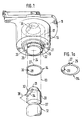
- FIG. 1 shows, as a first exemplary embodiment, a distributor rotor for ignition distributors of internal combustion engines with a section-wise end piece of the drive shaft and with a securing element
- FIG. 1a shows an alternative embodiment of the securing element
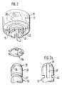
- FIG. 2 as a second exemplary embodiment the distributor rotor with a modified receptacle for a modified securing element
- FIG. 2a the drive shaft in a variant with anti-rotation protection.
- the ignition distributor for internal combustion engines partially shown in FIG. 1 for the distribution of ignition voltage pulses in a multi-cylinder internal combustion engine shows a distributor rotor 11 which can be connected to a drive shaft 12 designed as a distributor shaft in alignment with the reference lines 13 by means of a securing element 14.
- the distributor rotor 11 has a sleeve-shaped shaft 16 which is coaxial with the drive shaft 12 of the ignition distributor, with a bearing bush 17 which is fixedly arranged therein and protrudes out of the shaft 16 in the direction of the drive shaft 12 and here two hollow-cylindrical extensions, an upper extension 18 which corresponds to the Shaft 16 is adjacent and forms a lower shoulder 19 with a reduced diameter compared to the upper shoulder 18.
- an annular groove 21 with a rectangular cross section is provided on the lower attachment 19.
- the lower shoulder 19 is weakened by a lateral recess 23, which is arranged parallel to the axis of rotation 24 of the bearing bush 17, in the full axial height from the end face 22 of the lower shoulder to the upper shoulder 18.
- the recess 23 can be produced, for example, by a single milling process and has the shape of a flattening with a cross-section shaped as a segment of a circle. The radial distance between the milling cutter edge and the axis of rotation 24 is dimensioned such that the bearing bush 17 is broken through by the recess 23 and a circular segment with a chord 26 is formed in this area.
- the securing element 14, which in the first exemplary embodiment is made of spring wire, is circular below the distributor rotor 11 and is circular in its basic form and has a narrow-gap separation point 27.
- the securing element 14 deviates from its Keisring form and forms a chord-like shape 28, the length of the chord 30 of the chord 28 being one game longer than the length of the chord 26 of the recess 23.
- the securing element 14 can also take the form of a securing ring instead of a snap ring.
- FIG. 1 a shows this configuration as a securing element 114, the circular ring shape being preserved on the circumference in the region of the formation and the inner formation 28, deviating from the circular ring shape, running in a sinew-like manner and the length of the chord 30 of the formation 28 being greater by a joint play than the length of the chord 26 of the recess 23.
- FIG. 1 has the basic shape of a cylindrical shaft.
- the drive shaft 12 Adjacent to the securing element 14, the drive shaft 12 has an end face 31 which is tapered in diameter with respect to the shaft 33 of the drive shaft 12 by an insertion bevel 32.
- the drive shaft 12 also contains a fixing groove 34 corresponding to the prior art and not detailed, which can be coupled with a fixing shoulder 36 adapted to this in the bearing bush 17 and in this state forms an anti-rotation device between the drive shaft 12 and distributor rotor 11.
- annular groove 37 is introduced, the cross section of which widens conically to form an elevation angle 38 to the lateral surface of the shaft 33.
- This elevation angle is preferably in a range between 15 ° - 35 ° and is 25 ° in the first embodiment.
- the distributor rotor 11 is joined to the drive shaft 12 in such a way that, in a preparation step, the securing element 14 is pushed in a spread shape over the lower extension 19 and snapped into the annular groove 21, the recess 23 and the formation 28 abutting one another. Then the distributor rotor 11 is pushed with the bearing bush 17 onto the drive shaft 12, so that the lead-in chamfer 32 meets the shape 28 of the securing element 14.
- the securing element 14 is spread open and held in this shape by the shaft 33 until it engages with the formation 28 in the annular groove 37 by the resilient force of the securing element 14 at the end of the insertion.
- the cross section of the annular groove 37 is designed such that when the securing element 14 snaps into the annular groove 37, the chord 30 of the formation 28 and the chord 26 of the recess 23 lie against one another with a play and a positive connection between the distributor rotor 11, the securing element 14 and the drive shaft 12 is produced .
- the axial distance of the annular groove 37 to the fixing groove 34 or the annular groove 21 to the fixing shoulder 36 is matched to one another in such a way that the coupling between the securing element 14 and the annular groove 37 takes place together with the coupling between the fixing groove 34 and the fixing shoulder 36.
- the securing element 114 can be used instead of the securing element 14 in the assembly and latching process described above.
- This axial securing has the character of a releasable snap-in connection, since the securing element 14 can disengage again with the corresponding axial force by means of the elevation angle 38 of the annular groove 37 and the distributor rotor 11 can thus be detached from the drive shaft 12 again.
- FIG. 2 which shows the second exemplary embodiment, which modifies the first exemplary embodiment
- parts already described have the same reference symbols as in FIG. 1.
- the lower extension 19 is designed without the lateral recess 23 and instead has a central transverse groove 41 which cuts through the lower extension 19 at full axial height and two similar diametrically opposite recesses at the passage through the bearing bush 17 42 creates with a rectangular base.
- the securing element 114 of the first exemplary embodiment is embodied in the second exemplary embodiment as a securing element 214 in the form of a securing ring with two radially inward facing tabs 43 which, adapted to the recesses 42, engage in the annular groove 37 through them in the assembled state.
- the securing element 214 can be expanded by means of the two radially outwardly directed perforated lugs 29.
- a partial annular groove 44 with the same cross-sectional shape is fitted in the drive shaft 12, replacing the annular groove 37.
- a longitudinal groove 46 runs in the drive shaft 12, the cross-sectional area of which is adapted to the flap 43 by a play of movement.
- the axial extent of the longitudinal groove 46 corresponds to the distance between the end face 31 and the partial ring groove 44.
- the partial ring groove 44 is arranged opposite the longitudinal groove 46 and has such a circumferential extent that the partial ring groove 44 and the longitudinal groove 46 form depressions which are separate from one another.
- the joining of the distributor rotor 11 with the drive shaft 12 begins with the preparatory step that the securing element 214 is pushed over the lower extension 19 in the spread state so that the tabs 43 slide into the recess 42.
- the securing element 214 After snapping into the annular groove 21, the securing element 214 is fixed in position.
- the securing element 214 is held in this form by the shaft 33 until the tab 43 sliding on the shaft 33 reaches the partial ring groove 44 and thereby the securing element 14 is again completely in the annular groove 21 and with the tab 43 arranged opposite the longitudinal groove 46 in the partial ring groove 44 can snap into place.
Landscapes
- Engineering & Computer Science (AREA)
- General Engineering & Computer Science (AREA)
- Mechanical Engineering (AREA)
- Chemical & Material Sciences (AREA)
- Combustion & Propulsion (AREA)
- Ignition Installations For Internal Combustion Engines (AREA)
Applications Claiming Priority (2)
| Application Number | Priority Date | Filing Date | Title |
|---|---|---|---|
| DE8912039U | 1989-10-10 | ||
| DE8912039U DE8912039U1 (de) | 1989-10-10 | 1989-10-10 | Verteilerläufer von Zündverteilern für Brennkraftmaschinen |
Publications (2)
| Publication Number | Publication Date |
|---|---|
| EP0422372A2 true EP0422372A2 (fr) | 1991-04-17 |
| EP0422372A3 EP0422372A3 (en) | 1991-06-12 |
Family
ID=6843580
Family Applications (1)
| Application Number | Title | Priority Date | Filing Date |
|---|---|---|---|
| EP19900116429 Withdrawn EP0422372A3 (en) | 1989-10-10 | 1990-08-28 | Ignition distributor rotor for combustion engines |
Country Status (2)
| Country | Link |
|---|---|
| EP (1) | EP0422372A3 (fr) |
| DE (1) | DE8912039U1 (fr) |
Cited By (6)
| Publication number | Priority date | Publication date | Assignee | Title |
|---|---|---|---|---|
| EP0491665A3 (en) * | 1990-12-18 | 1992-11-25 | Nuova Sabaf S.P.A. | Flame spreader for gas burners for hobs |
| US6953160B2 (en) | 2000-05-16 | 2005-10-11 | Marioff Corporation Oy | Expanding mounting assembly for mounting a sprayhead to a wall |
| DE102007030982A1 (de) | 2007-07-04 | 2009-01-08 | Volkswagen Ag | Anordnung zur axialen Sicherung und/oder zum axialen Toleranzausgleich eines Maschinenelementes, insbesondere eines Lagers, auf oder an einer Welle |
| WO2010020733A1 (fr) * | 2008-08-21 | 2010-02-25 | Labinal | Dispositif de connexion entre un cable electrique et une structure conductrice, notamment pour circuit de retour de courant. |
| FR2941819A1 (fr) * | 2009-01-30 | 2010-08-06 | Peugeot Citroen Automobiles Sa | "dispositif pour liaison de masse" |
| EP3680501A1 (fr) * | 2019-01-14 | 2020-07-15 | Hamilton Sundstrand Corporation | Ensembles de bague de retenue |
Families Citing this family (4)
| Publication number | Priority date | Publication date | Assignee | Title |
|---|---|---|---|---|
| CN106037534B (zh) * | 2016-08-11 | 2019-04-16 | 广东美的生活电器制造有限公司 | 研磨器及其安装弹片以及豆浆机 |
| CN106037535B (zh) * | 2016-08-11 | 2022-03-08 | 广东美的生活电器制造有限公司 | 研磨器及其连接圈以及豆浆机 |
| CN106037533A (zh) * | 2016-08-11 | 2016-10-26 | 广东美的生活电器制造有限公司 | 研磨器和豆浆机 |
| CN106037523A (zh) * | 2016-08-11 | 2016-10-26 | 广东美的生活电器制造有限公司 | 研磨器及其连接圈以及豆浆机 |
Family Cites Families (4)
| Publication number | Priority date | Publication date | Assignee | Title |
|---|---|---|---|---|
| US1555439A (en) * | 1924-11-03 | 1925-09-29 | Stewart Warner Speedometer | Shaft and detachable gear |
| US2864967A (en) * | 1954-04-27 | 1958-12-16 | Gen Motors Corp | Ignition distributor |
| FR1204055A (fr) * | 1958-10-03 | 1960-01-22 | Lucas Industries Ltd | Distributeur d'allumage pour moteurs à explosion |
| DE1400767C3 (de) * | 1963-09-12 | 1975-07-03 | Hugo Benzing oHG, 7254 Münchingen | Sicherungsvorrichtung mit federnder, gewölbter Sicherungsscheibe |
-
1989
- 1989-10-10 DE DE8912039U patent/DE8912039U1/de not_active Expired - Lifetime
-
1990
- 1990-08-28 EP EP19900116429 patent/EP0422372A3/de not_active Withdrawn
Cited By (11)
| Publication number | Priority date | Publication date | Assignee | Title |
|---|---|---|---|---|
| EP0491665A3 (en) * | 1990-12-18 | 1992-11-25 | Nuova Sabaf S.P.A. | Flame spreader for gas burners for hobs |
| TR25576A (tr) * | 1990-12-18 | 1993-07-01 | Nuova Sabaf Spa | Ocaklardaki gaz memeleri icin alev yayicisi. |
| US6953160B2 (en) | 2000-05-16 | 2005-10-11 | Marioff Corporation Oy | Expanding mounting assembly for mounting a sprayhead to a wall |
| DE102007030982A1 (de) | 2007-07-04 | 2009-01-08 | Volkswagen Ag | Anordnung zur axialen Sicherung und/oder zum axialen Toleranzausgleich eines Maschinenelementes, insbesondere eines Lagers, auf oder an einer Welle |
| WO2010020733A1 (fr) * | 2008-08-21 | 2010-02-25 | Labinal | Dispositif de connexion entre un cable electrique et une structure conductrice, notamment pour circuit de retour de courant. |
| FR2935200A1 (fr) * | 2008-08-21 | 2010-02-26 | Labinal | Dispositif de connexion entre un cable electrique et une structure conductrice, notamment pour circuit de retour de courant |
| FR2935202A1 (fr) * | 2008-08-21 | 2010-02-26 | Labinal | Dispositif de connexion entre un cable electrique et une structure conductrice, notamment pour circuit de retour de courant |
| US8562371B2 (en) | 2008-08-21 | 2013-10-22 | Labinal | Connection device between an electrical cable and a conducting structure, especially for a current return circuit |
| FR2941819A1 (fr) * | 2009-01-30 | 2010-08-06 | Peugeot Citroen Automobiles Sa | "dispositif pour liaison de masse" |
| EP3680501A1 (fr) * | 2019-01-14 | 2020-07-15 | Hamilton Sundstrand Corporation | Ensembles de bague de retenue |
| US11105377B2 (en) | 2019-01-14 | 2021-08-31 | Hamilton Sundstrand Corporation | Retaining ring assemblies |
Also Published As
| Publication number | Publication date |
|---|---|
| DE8912039U1 (de) | 1991-02-07 |
| EP0422372A3 (en) | 1991-06-12 |
Similar Documents
| Publication | Publication Date | Title |
|---|---|---|
| EP0481212B1 (fr) | Articulation à rotule | |
| EP0678669B1 (fr) | Dispositif d'injection de combustible | |
| EP0726400B1 (fr) | Dispositif de fixation en matière plastique | |
| EP0561817B1 (fr) | Piston compose refroidi pour moteurs a combustion interne | |
| DE69817266T2 (de) | Federklemme zum Befestigen von einem Brennstoffeinspritzventil in einem Anschlusstutzen eines Brennstoffverteilers | |
| EP0383084A1 (fr) | Elément de connexion | |
| EP0103750B1 (fr) | Instrument à écrire | |
| EP0422372A2 (fr) | Rotor de distribution d'allumage pour moteurs à combustion | |
| DE4013875A1 (de) | Verbindung eines magnetventils mit einem gehaeuseblock | |
| EP0568075A1 (fr) | Raccord à fiche pour tubes flexibles ou conduites de tuyaux, notamment pour conduites de carburant de machines à combustion interne | |
| EP0631081B1 (fr) | Dispositif de connexion pour conduites avec collier de serrage fendu | |
| DE2246623A1 (de) | Befestigungsvorrichtung und damit zusammenwirkendes werkzeug | |
| DE29610026U1 (de) | Steck-Kupplung | |
| EP1364121B1 (fr) | Module de serrage | |
| EP0446466A1 (fr) | Dispositif de couplage de traversée de paroi pour une connexion électrique | |
| DE3933667C1 (en) | Combined radial and axial bearing bush - includes split bearing shells and two detachable thrust ring couplings | |
| EP1201852A2 (fr) | Serrure cylindrique avec une pièce de liaison entre des éléments d'un stator | |
| DE3309936A1 (de) | Nippel zum drehbaren anschluss eines schlauches | |
| DE10300647A1 (de) | Entkopplungselement | |
| DE102017223636B4 (de) | Montageeinheit sowie Fixierhülse für eine solche Montageeinheit | |
| EP0691502B1 (fr) | Raccord rapide pour tuyaux | |
| DE3341029A1 (de) | Steckverbindung fuer mit einem druckmittel beaufschlagbare systeme | |
| DE4016343C2 (fr) | ||
| DE3420404C1 (de) | Geschlitzter, drehbarer Kolbenring | |
| DE19536441A1 (de) | Federklammer zur Verbindung einer Einspritzdüse mit einer Einspritzleitung |
Legal Events
| Date | Code | Title | Description |
|---|---|---|---|
| PUAI | Public reference made under article 153(3) epc to a published international application that has entered the european phase |
Free format text: ORIGINAL CODE: 0009012 |
|
| AK | Designated contracting states |
Kind code of ref document: A2 Designated state(s): DE FR GB IT |
|
| PUAL | Search report despatched |
Free format text: ORIGINAL CODE: 0009013 |
|
| AK | Designated contracting states |
Kind code of ref document: A3 Designated state(s): DE FR GB IT |
|
| RHK1 | Main classification (correction) |
Ipc: F02P 7/02 |
|
| 17P | Request for examination filed |
Effective date: 19911106 |
|
| RAP3 | Party data changed (applicant data changed or rights of an application transferred) |
Owner name: ROBERT BOSCH GMBH |
|
| STAA | Information on the status of an ep patent application or granted ep patent |
Free format text: STATUS: THE APPLICATION IS DEEMED TO BE WITHDRAWN |
|
| 18D | Application deemed to be withdrawn |
Effective date: 19930302 |