EP0422405A1 - Pièce de carrosserie automobile contenant un dispositif d'éclairage - Google Patents
Pièce de carrosserie automobile contenant un dispositif d'éclairage Download PDFInfo
- Publication number
- EP0422405A1 EP0422405A1 EP90117664A EP90117664A EP0422405A1 EP 0422405 A1 EP0422405 A1 EP 0422405A1 EP 90117664 A EP90117664 A EP 90117664A EP 90117664 A EP90117664 A EP 90117664A EP 0422405 A1 EP0422405 A1 EP 0422405A1
- Authority
- EP
- European Patent Office
- Prior art keywords
- bodywork component
- lighting device
- recess
- connection
- headlamp
- Prior art date
- Legal status (The legal status is an assumption and is not a legal conclusion. Google has not performed a legal analysis and makes no representation as to the accuracy of the status listed.)
- Granted
Links
Images

Classifications
-
- B—PERFORMING OPERATIONS; TRANSPORTING
- B60—VEHICLES IN GENERAL
- B60Q—ARRANGEMENT OF SIGNALLING OR LIGHTING DEVICES, THE MOUNTING OR SUPPORTING THEREOF OR CIRCUITS THEREFOR, FOR VEHICLES IN GENERAL
- B60Q1/00—Arrangement of optical signalling or lighting devices, the mounting or supporting thereof or circuits therefor
- B60Q1/02—Arrangement of optical signalling or lighting devices, the mounting or supporting thereof or circuits therefor the devices being primarily intended to illuminate the way ahead or to illuminate other areas of way or environments
- B60Q1/04—Arrangement of optical signalling or lighting devices, the mounting or supporting thereof or circuits therefor the devices being primarily intended to illuminate the way ahead or to illuminate other areas of way or environments the devices being headlights
- B60Q1/0408—Arrangement of optical signalling or lighting devices, the mounting or supporting thereof or circuits therefor the devices being primarily intended to illuminate the way ahead or to illuminate other areas of way or environments the devices being headlights built into the vehicle body, e.g. details concerning the mounting of the headlamps on the vehicle body
- B60Q1/0433—Arrangement of optical signalling or lighting devices, the mounting or supporting thereof or circuits therefor the devices being primarily intended to illuminate the way ahead or to illuminate other areas of way or environments the devices being headlights built into the vehicle body, e.g. details concerning the mounting of the headlamps on the vehicle body the housing being fastened onto the vehicle body using screws
-
- B—PERFORMING OPERATIONS; TRANSPORTING
- B60—VEHICLES IN GENERAL
- B60Q—ARRANGEMENT OF SIGNALLING OR LIGHTING DEVICES, THE MOUNTING OR SUPPORTING THEREOF OR CIRCUITS THEREFOR, FOR VEHICLES IN GENERAL
- B60Q1/00—Arrangement of optical signalling or lighting devices, the mounting or supporting thereof or circuits therefor
- B60Q1/02—Arrangement of optical signalling or lighting devices, the mounting or supporting thereof or circuits therefor the devices being primarily intended to illuminate the way ahead or to illuminate other areas of way or environments
- B60Q1/04—Arrangement of optical signalling or lighting devices, the mounting or supporting thereof or circuits therefor the devices being primarily intended to illuminate the way ahead or to illuminate other areas of way or environments the devices being headlights
- B60Q1/0408—Arrangement of optical signalling or lighting devices, the mounting or supporting thereof or circuits therefor the devices being primarily intended to illuminate the way ahead or to illuminate other areas of way or environments the devices being headlights built into the vehicle body, e.g. details concerning the mounting of the headlamps on the vehicle body
- B60Q1/0425—Arrangement of optical signalling or lighting devices, the mounting or supporting thereof or circuits therefor the devices being primarily intended to illuminate the way ahead or to illuminate other areas of way or environments the devices being headlights built into the vehicle body, e.g. details concerning the mounting of the headlamps on the vehicle body the housing being swivel mounted on the vehicle body
Definitions
- the present invention relates to a vehicle bodywork component incorporating a lighting device.
- the present invention relates in particular, but not exclusively, to a bumper of an industrial vehicle incorporating a headlamp.
- headlamps are normally inserted in a recess formed in the vehicle body or in the bumpers of the vehicle.
- the outer body of the headlamp is generally inserted in this recess and is permanently connected to the body or bumper by fastening means which do not allow the headlamp to be rapidly and readily assembled and dismantled. Operations to maintain the headlamp (for instance the replacement of the light source) are somewhat problematic for this reason and take a comparatively long time to perform.
- the object of the present invention is to construct a portion of the bodywork of a vehicle so that the assembly and dismantling of a lighting device can be readily carried out, thereby remedying the drawbacks of the known systems discussed above.
- the present invention provides a vehicle bodywork component of the type comprising a recess housing a lighting device and means for securing this lighting device in the recess, characterized in that the fastening means comprise at least one hinge interposed between the bodywork component and the lighting device and in that the hinge is adapted to allow the lighting device to rotate between a first position in which it is housed in the recess and a second position in which it is extracted from the recess.
- a vehicle bodywork component in particular a bumper, is designated overall by 1 and has a recess 3, communicating externally via a hole 4, adapted to house a headlamp 5.
- the headlamp 5 is bounded laterally by a vertical curved wall 6 from which a transparent member 7 extends at the front; the wall 6 is connected to a base wall 8 and two plane upper 9 and lower walls (only one of which is shown in the Figure) perpendicular to the walls 6 and 8.
- the headlamp 5 also has a shape such that it can be completely contained in the recess 3 and is rigid, at one lateral end, with a vertical hinge 11 which is secured to the bumper 1 in the vicinity of a vertical edge 12 of the hole 4.
- the wall 8 has means 15 for connecting and securing the headlamp 5 to the bumper 1.
- These means 15 are adapted to be connected to respective connection and securing means 16 borne by a peripheral wall 17 of the recess 3 and are disposed in the vicinity of a vertical edge 18 of the hole 4.
- the hinge 11 comprises two plates 19 and 20 which are hinged together about a pin 21.
- the plate 19 has a through hole 22 for connection with a projection 52 extending in a detachable manner from the wall 6 of the headlamp 1; the plate 20 has a through hole 23 for connection to the bumper 1.
- connection of the plate 19 to the projection 52 takes place via a screw 30, passing through the hole 22 and a through hole 29 in the projection 52 itself, and a locking nut 31.
- connection of the plate 20 to the bumper 1 takes place via a pin 24 with a toothed portion 25 and a threaded head 26.
- the portion 25 is fitted in a blind hole formed in a projection 27 emerging internally from the bumper 1, while the threaded head 26 engages with the through hole 23 of the plate 20 and is made rigid with the latter by a locking nut 28.
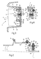
- Fig. 3 the headlamp 5 is shown in a different position to that of the headlamp 5 in Fig. 1; the headlamp 5 is in particular shown completely inserted in the recess 3 and is shown partly in section and partly in dashed lines.
- Fig. 3 clearly shows the recess 3 in the bumper 1 which is bounded by the peripheral wall 17 and by an upper wall 32 and a lower wall 33 both substantially perpendicular to the wall 17 and formed in one piece with the wall 17.
- Two projections 34 and 35 of frustoconical shape which are substantially identical and are obtained in one piece with the wall 17 extend from the wall 17 towards the interior of the recess 3.
- the wall 17 is provided with a through hole 36 which is located between the projections 34 and 35 and is substantially aligned with these projections 34 and 35.
- a screw 37 whose shank has a radial annular groove engaged by an elastic segment 46 which engages with the wall 17 thereby preventing the screw 37 from moving axially with respect to the hole 36 is inserted in the hole 36.
- the projections 34, 35 and the screw 37 form the connection and securing means 16 borne by the bumper 1.
- Two cup-shaped members 38 and 39 with a substantially frustoconical mouth are provided in the wall 14 of the headlamp 5, which members define respective housings for the projections 34 and 35.
- the wall 14 also has a through hole 40 which is substantially aligned with the members 38 and 39 and is coaxial with the hole 36 in the wall 17 of the bumper 1.
- the hole 40 houses a nut 45 which is adapted to engage in use with the screw 37 so as to form a permanent connection between the bumper 1 and the headlamp 5.
- the cup-shaped members 38, 39 and the nut 45 form the connection and securing means 15 borne by the headlamp 5.
- Fig. 4 shows an equivalent solution in respect of the securing means 15 described above; since none of the other details have been changed, the same reference numerals have been used to identify details described above with reference to Fig. 3 which are identical.
- the projection 34 is in this case replaced by a substantially conical boss 41 with a rounded vertex made from an elastically deformable material.
- the boss 41 is stamped together with the threaded shank 42 which engages with a through hole 43 in the wall 17.
- the shank 43 is screwed to a nut 44 which, by pressing on the wall 17 of the bumper 1, provides the connection between the boss 41 and the wall 17.
- the headlamp 5 is completely inserted within the recess 3 and is secured to the bumper 1 by the hinge 11 and by the connection of the means 15 and 16.
- the screw 37 engages with the nut 45 and permanently connects the bumper 1 to the headlamp 5. In this way the headlamp 5 cannot rotate about the hinge 11 and is permanently inserted in the recess 3.
- the means for connecting the headlamp could in particular be advantageously used to secure the headlamp to bodywork components in general and the headlamp could also be replaced by any similar lighting device, for instance an optical indicator unit.
- connection and securing means could also be modified, for example by replacing the screw 37 and the nut 45 by a generic snap-locking mechanism which can be disengaged from outside.
Landscapes
- Engineering & Computer Science (AREA)
- Mechanical Engineering (AREA)
- Lighting Device Outwards From Vehicle And Optical Signal (AREA)
- Non-Portable Lighting Devices Or Systems Thereof (AREA)
Applications Claiming Priority (2)
| Application Number | Priority Date | Filing Date | Title |
|---|---|---|---|
| IT05341489U IT221656Z2 (it) | 1989-10-13 | 1989-10-13 | Elemento di carrozzeria di un veicolo incorporante un dispositivo di illuminazione. |
| IT5341489U | 1989-10-13 |
Publications (2)
| Publication Number | Publication Date |
|---|---|
| EP0422405A1 true EP0422405A1 (fr) | 1991-04-17 |
| EP0422405B1 EP0422405B1 (fr) | 1994-12-14 |
Family
ID=11282541
Family Applications (1)
| Application Number | Title | Priority Date | Filing Date |
|---|---|---|---|
| EP90117664A Expired - Lifetime EP0422405B1 (fr) | 1989-10-13 | 1990-09-13 | Pièce de carrosserie automobile contenant un dispositif d'éclairage |
Country Status (4)
| Country | Link |
|---|---|
| EP (1) | EP0422405B1 (fr) |
| DE (1) | DE69015097T2 (fr) |
| ES (1) | ES2066072T3 (fr) |
| IT (1) | IT221656Z2 (fr) |
Cited By (15)
| Publication number | Priority date | Publication date | Assignee | Title |
|---|---|---|---|---|
| JPH0636978U (ja) * | 1992-10-21 | 1994-05-17 | 三菱自動車工業株式会社 | ヘッドランプ取付構造 |
| US6190030B1 (en) | 1999-02-18 | 2001-02-20 | Lacks Industries, Inc. | Flexible lamp mounting |
| EP1103417A1 (fr) | 1999-11-29 | 2001-05-30 | Valeo Vision | Véhicule à dispositif d'éclairage et/ou de signalisation monté mobile |
| EP0894663A3 (fr) * | 1997-07-30 | 2002-01-16 | Robert Bosch Gmbh | Dispositif de fixation d'une unité d'éclairage pour véhicule |
| US6502974B2 (en) | 1999-02-18 | 2003-01-07 | Lacks Enterprises, Inc. | Integrated flexible lamp assembly |
| EP1514771A1 (fr) * | 2003-09-12 | 2005-03-16 | Dr.Ing. h.c.F. Porsche Aktiengesellschaft | Dispositif de fixation d'un élément dans un orifice dans la pièce de carosserie |
| FR2876067A1 (fr) * | 2004-10-05 | 2006-04-07 | Valeo Vision Sa | Systeme de montage d'un projecteur sur un vehicule automobile et vehicule automobile comportant un tel systeme |
| EP1332915A3 (fr) * | 2002-01-30 | 2007-02-21 | Ford Global Technologies, Inc. | Projecteur avec dispositif de protection des piétons |
| US7264388B2 (en) * | 2004-05-11 | 2007-09-04 | Dr. Ing. H.C.F. Porsche Aktiengesellschaft | Motor vehicle having an illuminating device receiving system for an exterior illuminating device |
| JP2007246019A (ja) * | 2006-03-17 | 2007-09-27 | Mitsubishi Fuso Truck & Bus Corp | 車両のフロントバンパー構造 |
| EP1987984A1 (fr) * | 2007-05-04 | 2008-11-05 | Valeo Vision | Dispositif pour le remplacement d'une source lumineuse de module optique de véhicule automobile. |
| DE19950592B4 (de) * | 1998-10-21 | 2010-04-15 | Valeo Vision | Beleuchtungs- oder Signalvorrichtung für Automobile mit neuartigen Zugriffsmitteln auf eine Lampe |
| DE102011011701A1 (de) * | 2011-02-18 | 2012-08-23 | Gm Global Technology Operations, Llc | Montageträger für Frontscheinwerfer |
| JP2018122775A (ja) * | 2017-02-02 | 2018-08-09 | トヨタ車体株式会社 | 車両のランプ取付け構造 |
| EP4342760A1 (fr) * | 2022-09-23 | 2024-03-27 | ALSTOM Holdings | Tête de véhicule d'un véhicule ferroviaire comprenant une unité d'équipement ouvrable positionnée de manière centrale |
Citations (3)
| Publication number | Priority date | Publication date | Assignee | Title |
|---|---|---|---|---|
| DE401786C (de) * | 1924-09-10 | Herm Riemann Fa | Abblendbarer Scheinwerfer fuer Fahrzeuge | |
| DE506415C (de) * | 1930-09-03 | Fried Krupp Akt Ges | Scheinwerfer fuer Fahrzeuge, insbesondere Kraftfahrzeuge | |
| DE2030144A1 (fr) * | 1970-04-29 | 1971-12-23 | Siemens Ag |
-
1989
- 1989-10-13 IT IT05341489U patent/IT221656Z2/it active IP Right Grant
-
1990
- 1990-09-13 ES ES90117664T patent/ES2066072T3/es not_active Expired - Lifetime
- 1990-09-13 DE DE69015097T patent/DE69015097T2/de not_active Expired - Lifetime
- 1990-09-13 EP EP90117664A patent/EP0422405B1/fr not_active Expired - Lifetime
Patent Citations (3)
| Publication number | Priority date | Publication date | Assignee | Title |
|---|---|---|---|---|
| DE401786C (de) * | 1924-09-10 | Herm Riemann Fa | Abblendbarer Scheinwerfer fuer Fahrzeuge | |
| DE506415C (de) * | 1930-09-03 | Fried Krupp Akt Ges | Scheinwerfer fuer Fahrzeuge, insbesondere Kraftfahrzeuge | |
| DE2030144A1 (fr) * | 1970-04-29 | 1971-12-23 | Siemens Ag |
Cited By (19)
| Publication number | Priority date | Publication date | Assignee | Title |
|---|---|---|---|---|
| JPH0636978U (ja) * | 1992-10-21 | 1994-05-17 | 三菱自動車工業株式会社 | ヘッドランプ取付構造 |
| EP0894663A3 (fr) * | 1997-07-30 | 2002-01-16 | Robert Bosch Gmbh | Dispositif de fixation d'une unité d'éclairage pour véhicule |
| DE19950592B4 (de) * | 1998-10-21 | 2010-04-15 | Valeo Vision | Beleuchtungs- oder Signalvorrichtung für Automobile mit neuartigen Zugriffsmitteln auf eine Lampe |
| US6190030B1 (en) | 1999-02-18 | 2001-02-20 | Lacks Industries, Inc. | Flexible lamp mounting |
| US6502974B2 (en) | 1999-02-18 | 2003-01-07 | Lacks Enterprises, Inc. | Integrated flexible lamp assembly |
| EP1103417A1 (fr) | 1999-11-29 | 2001-05-30 | Valeo Vision | Véhicule à dispositif d'éclairage et/ou de signalisation monté mobile |
| EP1332915A3 (fr) * | 2002-01-30 | 2007-02-21 | Ford Global Technologies, Inc. | Projecteur avec dispositif de protection des piétons |
| EP1514771A1 (fr) * | 2003-09-12 | 2005-03-16 | Dr.Ing. h.c.F. Porsche Aktiengesellschaft | Dispositif de fixation d'un élément dans un orifice dans la pièce de carosserie |
| US7014254B2 (en) | 2003-09-12 | 2006-03-21 | Dr. Ing. H.C.F. Porsche Aktiengesellschaft | Fastening device for a component installed in a depression in an automotive body part |
| US7264388B2 (en) * | 2004-05-11 | 2007-09-04 | Dr. Ing. H.C.F. Porsche Aktiengesellschaft | Motor vehicle having an illuminating device receiving system for an exterior illuminating device |
| EP1645465A1 (fr) * | 2004-10-05 | 2006-04-12 | Valeo Vision | Système de montage d'un projecteur sur un véhicule automobile et véhicule automobile comportant un tel système |
| FR2876067A1 (fr) * | 2004-10-05 | 2006-04-07 | Valeo Vision Sa | Systeme de montage d'un projecteur sur un vehicule automobile et vehicule automobile comportant un tel systeme |
| US7946745B2 (en) | 2004-10-05 | 2011-05-24 | Valeo Vision | System for mounting a headlight on a motor vehicle and a motor vehicle comprising such a system |
| JP2007246019A (ja) * | 2006-03-17 | 2007-09-27 | Mitsubishi Fuso Truck & Bus Corp | 車両のフロントバンパー構造 |
| EP1987984A1 (fr) * | 2007-05-04 | 2008-11-05 | Valeo Vision | Dispositif pour le remplacement d'une source lumineuse de module optique de véhicule automobile. |
| FR2915718A1 (fr) * | 2007-05-04 | 2008-11-07 | Valeo Vision Sa | Dispositif pour le remplacement d'une source lumineuse de module optique de vehicule automobile |
| DE102011011701A1 (de) * | 2011-02-18 | 2012-08-23 | Gm Global Technology Operations, Llc | Montageträger für Frontscheinwerfer |
| JP2018122775A (ja) * | 2017-02-02 | 2018-08-09 | トヨタ車体株式会社 | 車両のランプ取付け構造 |
| EP4342760A1 (fr) * | 2022-09-23 | 2024-03-27 | ALSTOM Holdings | Tête de véhicule d'un véhicule ferroviaire comprenant une unité d'équipement ouvrable positionnée de manière centrale |
Also Published As
| Publication number | Publication date |
|---|---|
| DE69015097T2 (de) | 1995-07-20 |
| EP0422405B1 (fr) | 1994-12-14 |
| IT221656Z2 (it) | 1994-07-25 |
| ES2066072T3 (es) | 1995-03-01 |
| IT8953414V0 (it) | 1989-10-13 |
| IT8953414U1 (it) | 1991-04-13 |
| DE69015097D1 (de) | 1995-01-26 |
Similar Documents
| Publication | Publication Date | Title |
|---|---|---|
| EP0422405A1 (fr) | Pièce de carrosserie automobile contenant un dispositif d'éclairage | |
| KR920008022B1 (ko) | 직교변환 기어장치 | |
| US4290098A (en) | Receptacle apparatus for housing components of a lighting system | |
| EP0460893B1 (fr) | Rétroviseur rabattable à pivotement sur tourillon | |
| US5186532A (en) | Headlamp adjusting mechanism and headlamp adjusting assembly | |
| EP0415899A1 (fr) | Dispositif de fixation | |
| EP0925716A1 (fr) | Mécanisme d'articulation pour faucheuse | |
| US5624029A (en) | Tool box with a lighting apparatus | |
| US6135619A (en) | Device for fixing a light unit on a car body comprising an extensible spring | |
| US5414603A (en) | Airport lighting unit | |
| JPS5937971B2 (ja) | 歯科機械のタ−ビンエルボ頭部へのタ−ビン組込具 | |
| CN113952034B (zh) | 一种快拆手术器械 | |
| US5163746A (en) | Assembly for headlamp adjustment | |
| JP4928243B2 (ja) | カメラと/又は照明装置付き自動車ドア用バック・ミラー | |
| US3208031A (en) | Lamp socket with shock-free mounting | |
| US20090052201A1 (en) | Lamp for motor vehicles | |
| GB2302323A (en) | Container having a closure cover | |
| EP0268759B1 (fr) | Phare du type projecteur pour véhicules | |
| EP0994436B1 (fr) | Appareil electro-optique portable | |
| EP0431803A2 (fr) | Montage pour lampe | |
| US5446630A (en) | Optical-axis adjustment checker for automotive headlamps | |
| GB2176395A (en) | Castors | |
| CA2010363A1 (fr) | Moteur d'entrainement pour fenetres a manoeuvre par cables | |
| CN208154358U (zh) | 一种光栅固定结构和一种闪光灯 | |
| KR0150747B1 (ko) | 차량용 경고등 |
Legal Events
| Date | Code | Title | Description |
|---|---|---|---|
| PUAI | Public reference made under article 153(3) epc to a published international application that has entered the european phase |
Free format text: ORIGINAL CODE: 0009012 |
|
| AK | Designated contracting states |
Kind code of ref document: A1 Designated state(s): DE ES FR GB IT NL SE |
|
| 17P | Request for examination filed |
Effective date: 19911014 |
|
| 17Q | First examination report despatched |
Effective date: 19930602 |
|
| GRAA | (expected) grant |
Free format text: ORIGINAL CODE: 0009210 |
|
| AK | Designated contracting states |
Kind code of ref document: B1 Designated state(s): DE ES FR GB IT NL SE |
|
| REF | Corresponds to: |
Ref document number: 69015097 Country of ref document: DE Date of ref document: 19950126 |
|
| EAL | Se: european patent in force in sweden |
Ref document number: 90117664.4 |
|
| ITF | It: translation for a ep patent filed | ||
| ET | Fr: translation filed | ||
| REG | Reference to a national code |
Ref country code: ES Ref legal event code: FG2A Ref document number: 2066072 Country of ref document: ES Kind code of ref document: T3 |
|
| PLBE | No opposition filed within time limit |
Free format text: ORIGINAL CODE: 0009261 |
|
| STAA | Information on the status of an ep patent application or granted ep patent |
Free format text: STATUS: NO OPPOSITION FILED WITHIN TIME LIMIT |
|
| 26N | No opposition filed | ||
| REG | Reference to a national code |
Ref country code: GB Ref legal event code: IF02 |
|
| NLT1 | Nl: modifications of names registered in virtue of documents presented to the patent office pursuant to art. 16 a, paragraph 1 |
Owner name: IVECO S.P.A. |
|
| REG | Reference to a national code |
Ref country code: FR Ref legal event code: CD |
|
| PG25 | Lapsed in a contracting state [announced via postgrant information from national office to epo] |
Ref country code: IT Free format text: LAPSE BECAUSE OF NON-PAYMENT OF DUE FEES;WARNING: LAPSES OF ITALIAN PATENTS WITH EFFECTIVE DATE BEFORE 2007 MAY HAVE OCCURRED AT ANY TIME BEFORE 2007. THE CORRECT EFFECTIVE DATE MAY BE DIFFERENT FROM THE ONE RECORDED. Effective date: 20050913 |
|
| PGFP | Annual fee paid to national office [announced via postgrant information from national office to epo] |
Ref country code: FR Payment date: 20090826 Year of fee payment: 20 Ref country code: ES Payment date: 20090828 Year of fee payment: 20 |
|
| PGFP | Annual fee paid to national office [announced via postgrant information from national office to epo] |
Ref country code: GB Payment date: 20090902 Year of fee payment: 20 Ref country code: NL Payment date: 20090827 Year of fee payment: 20 Ref country code: SE Payment date: 20090826 Year of fee payment: 20 |
|
| PGFP | Annual fee paid to national office [announced via postgrant information from national office to epo] |
Ref country code: DE Payment date: 20090827 Year of fee payment: 20 |
|
| REG | Reference to a national code |
Ref country code: NL Ref legal event code: V4 Effective date: 20100913 |
|
| REG | Reference to a national code |
Ref country code: GB Ref legal event code: PE20 Expiry date: 20100912 |
|
| EUG | Se: european patent has lapsed | ||
| PG25 | Lapsed in a contracting state [announced via postgrant information from national office to epo] |
Ref country code: GB Free format text: LAPSE BECAUSE OF EXPIRATION OF PROTECTION Effective date: 20100912 |
|
| PG25 | Lapsed in a contracting state [announced via postgrant information from national office to epo] |
Ref country code: NL Free format text: LAPSE BECAUSE OF EXPIRATION OF PROTECTION Effective date: 20100913 |
|
| PGFP | Annual fee paid to national office [announced via postgrant information from national office to epo] |
Ref country code: IT Payment date: 20090903 Year of fee payment: 20 |
|
| PGRI | Patent reinstated in contracting state [announced from national office to epo] |
Ref country code: IT Effective date: 20110616 |
|
| REG | Reference to a national code |
Ref country code: ES Ref legal event code: FD2A Effective date: 20120511 |
|
| PG25 | Lapsed in a contracting state [announced via postgrant information from national office to epo] |
Ref country code: ES Free format text: LAPSE BECAUSE OF EXPIRATION OF PROTECTION Effective date: 20100914 |
|
| PG25 | Lapsed in a contracting state [announced via postgrant information from national office to epo] |
Ref country code: DE Free format text: LAPSE BECAUSE OF EXPIRATION OF PROTECTION Effective date: 20100913 |