EP0422410A2 - Limiteur de tension pour systèmes de retenue à ceinture de sécurité - Google Patents
Limiteur de tension pour systèmes de retenue à ceinture de sécurité Download PDFInfo
- Publication number
- EP0422410A2 EP0422410A2 EP90117721A EP90117721A EP0422410A2 EP 0422410 A2 EP0422410 A2 EP 0422410A2 EP 90117721 A EP90117721 A EP 90117721A EP 90117721 A EP90117721 A EP 90117721A EP 0422410 A2 EP0422410 A2 EP 0422410A2
- Authority
- EP
- European Patent Office
- Prior art keywords
- cylinder
- fitting
- force limiter
- rolling elements
- limiter according
- Prior art date
- Legal status (The legal status is an assumption and is not a legal conclusion. Google has not performed a legal analysis and makes no representation as to the accuracy of the status listed.)
- Granted
Links
Images

Classifications
-
- B—PERFORMING OPERATIONS; TRANSPORTING
- B60—VEHICLES IN GENERAL
- B60R—VEHICLES, VEHICLE FITTINGS, OR VEHICLE PARTS, NOT OTHERWISE PROVIDED FOR
- B60R22/00—Safety belts or body harnesses in vehicles
- B60R22/28—Safety belts or body harnesses in vehicles incorporating energy-absorbing devices
Definitions
- the invention relates to a force limiter for seat belt restraint systems, having at least one cylinder on which a first fitting acts, and a rod which is received in the cylinder in a longitudinally displaceable manner and on the end of which protrudes from the cylinder, a second fitting acts, the force limiter acting on the first and the second fitting is inserted into the power flow path of the seat belt system.
- Force limiters of this type have the task of reducing load peaks in the seat belt system and thus protecting the vehicle occupants from high acceleration values.
- Various designs of force limiters have already been proposed. But there is still a need for special Space-saving, yet highly effective force limiters that can be easily integrated into standard seat belt restraint systems.
- the invention has for its object to provide a force limiter for seat belt restraint systems, which is characterized by a small size and can be easily integrated into conventional seat belt restraint systems.
- a force limiter of the type mentioned at the outset in that in an annular free space which is delimited radially on the inside by the rod, radially on the outside by the inner wall of the cylinder and axially on at least one side by an annular shoulder, a plurality of rolling elements in the circumferential direction are evenly distributed and that the material properties of the cylinder and the diameter of the rolling elements are coordinated so that the rod and the cylinder under tensile load between the fittings against a reproducibly defined inhibiting force and with deformation of the inner wall of the cylinder and formation of longitudinal grooves by penetration of the Rolling elements are pulled apart into the material of the cylinder.
- the rolling elements are steel balls, while the cylinder consists of a material such as aluminum or an aluminum alloy.
- a hard material is therefore preferably used for the rolling elements, while a relatively soft material is used for the cylinder wall, which material is easily deformable plastically.
- the cylinder is designed as a simple tube which is provided with a fastening thread at one end or is squeezed flat into a fitting part and is compressed at its other end in order to form a stop for the rolling elements which prevents the rod from being pulled completely out of the cylinder.
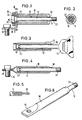
- a rod 12 is received in a cylindrical tube 10 made of aluminum, one end 14 of which protrudes from the cylinder 10 and the other end is provided with a piston-like head 16.
- the outside diameter of the collar 12 is smaller than the inside diameter of the cylinder bore 18.
- the head 16 is received with little play in an enlarged bore section 20 of the cylinder 10, which merges into the cylinder bore 18 via a step or shoulder.
- a free space is formed, which is delimited radially on the inside by the outer surface of the rod 12 and in which a number of rolling elements 22 are arranged evenly distributed in the circumferential direction .
- a total of eight rolling elements 22 are present, which are designed as steel balls and are at least approximately adjacent to one another in the circumferential direction.
- the outer diameter of the ring arrangement formed by the rolling elements 22 is larger than the inner diameter of the cylinder bore 18.
- the cylinder 10 is provided at its end adjacent to the head 16 with an external thread 24, on which a screw nut 26 can be screwed, around a fitting part 28 in the form of a Attach the angle plate to the cylinder 10.
- the opposite end of the cylinder 10 is provided with an annular shoulder 30 directed radially inwards and forming a stop for the rolling elements 22. That out of the cylinder 10 End of the rod 12 is provided with an external thread 32 for fastening a second fitting.
- the force limiter described is inserted into the force flow of a seat belt restraint system via the fitting 28 and the fitting attached to the rod 12.
- the fitting 28 is fastened to the vehicle body by means of a screw bolt 34, while a belt buckle, a deflection fitting or the like is fastened to the rod 12 by means of the external thread 32.
- the rolling elements 22 penetrate into the material of the inner wall of the cylinder 10 and press it radially outward and axially in the direction of pull, so that parallel longitudinal grooves on the inside of the Cylinder bore 18 are formed. These longitudinal grooves can have a depth of a few tenths of a millimeter.
- the cylinder 10 can also be made of a harder material than aluminum, for example a relatively thin steel tube, if the rolling elements 22 are made of hardened steel. With such a choice of material, a larger proportion of deformation work and a relatively smaller proportion of work for plastic deformation are performed.
- Fig. 3 differs from that of Figures 1 and 2 only in that the rolling elements 22 are received in a circumferential groove 40 at the end of the rod 12 and this otherwise over its entire length has the same diameter. Furthermore, a fitting 42 in the form of an eyelet is molded onto its end protruding from the cylinder 10.
- FIGS. 4 and 6 differs from that according to FIG. 3 in that the cylinder 10 is squeezed flat at its end adjacent to the rolling bodies 22 to form a fitting part 46.
- the fitting part 46 provided with a bore can be fastened directly to the vehicle body or, for example, also to the vehicle seat by means of a fastening bolt 34.
- the annular shoulder 30 at the end of the cylinder 10 facing away from the fitting part 46 can be produced by compression, so that the entire cylinder 10 can be produced from a simple tube section.
- a fitting part 50 is inserted into a slot at the free end of the rod 12 and fastened there.
- FIG. 7 The embodiment shown in Fig. 7 is particularly suitable for a passive seat belt system.
- two cylinders 10A, 10B are arranged parallel to one another and along the side edges of the fitting plate 60.
- a rod 12A, 12B protrudes from each cylinder 10A, 10B.
- the unit formed from cylinder 10A, 10B and rod 12A, 12B is in principle constructed in the same way as the previously described embodiments of the force limiter.
- 8 shows a circumferential groove 40A, 40B at the end of the rod 12A, 12B and the corresponding rolling elements 22A, 22B.
- the rods 12A, 12B are each provided with a screwed-on head piece 16A, 16B at their end accommodated in the cylinder 10A, 10B.
- the rods 12A, 12B are interconnected by a generally U-shaped bracket 12C which, in the preferred embodiment, is integrally formed with these rods. Between the cylinders 10A, 10B there is one on the fitting plate 60 Inserted tongue 64 attached and a sliding track for a small buckle 66 formed. A fitting part 68 is connected to the bracket 12C, of which FIGS. 7 and 8 each show a variant.
Landscapes
- Engineering & Computer Science (AREA)
- Mechanical Engineering (AREA)
- Automotive Seat Belt Assembly (AREA)
Applications Claiming Priority (2)
| Application Number | Priority Date | Filing Date | Title |
|---|---|---|---|
| DE3933721A DE3933721A1 (de) | 1989-10-09 | 1989-10-09 | Kraftbegrenzer fuer sicherheitsgurt-rueckhaltesysteme |
| DE3933721 | 1989-10-09 |
Publications (3)
| Publication Number | Publication Date |
|---|---|
| EP0422410A2 true EP0422410A2 (fr) | 1991-04-17 |
| EP0422410A3 EP0422410A3 (en) | 1992-02-26 |
| EP0422410B1 EP0422410B1 (fr) | 1994-05-25 |
Family
ID=6391137
Family Applications (1)
| Application Number | Title | Priority Date | Filing Date |
|---|---|---|---|
| EP90117721A Expired - Lifetime EP0422410B1 (fr) | 1989-10-09 | 1990-09-14 | Limiteur de tension pour systèmes de retenue à ceinture de sécurité |
Country Status (5)
| Country | Link |
|---|---|
| US (1) | US5069482A (fr) |
| EP (1) | EP0422410B1 (fr) |
| JP (1) | JPH0818532B2 (fr) |
| DE (2) | DE3933721A1 (fr) |
| ES (2) | ES2022083T3 (fr) |
Cited By (3)
| Publication number | Priority date | Publication date | Assignee | Title |
|---|---|---|---|---|
| EP0557863A3 (fr) * | 1992-02-27 | 1994-04-20 | Trw Repa Gmbh | |
| US5480190A (en) * | 1992-02-27 | 1996-01-02 | Trw Repa Gmbh | Energy converter in a restraining system for vehicle occupants |
| WO1996016843A1 (fr) * | 1994-11-28 | 1996-06-06 | Alliedsignal Inc. | Dispositif de rappel de ceinture de securite comportant un enrouleur a absorption d'energie d'un seul cote |
Families Citing this family (11)
| Publication number | Priority date | Publication date | Assignee | Title |
|---|---|---|---|---|
| US5732974A (en) * | 1997-03-03 | 1998-03-31 | Trw Vehicle Safety Systems Inc. | Seat belt system energy management device replacement indicator |
| DE19758497C2 (de) * | 1997-11-11 | 2001-02-22 | Giok Djien Go | Energieabsorber für ein Rückhaltesystem in Fahrzeugen, Zügen und Flugzeugen |
| DE19758498C2 (de) | 1997-11-11 | 2001-07-05 | Giok Djien Go | Rückhaltesystem mit Schulter- und/oder Halshalter zur Erhöhung des Insassenschutzes |
| US6045174A (en) * | 1998-08-31 | 2000-04-04 | Ford Global Technologies, Inc. | Vehicle seat with support assembly |
| US6659505B1 (en) | 2000-01-12 | 2003-12-09 | Autoliv Asp, Inc. | Adaptive variable load limited for primary occupant safety restraint |
| DE10013870B4 (de) | 2000-03-21 | 2007-04-05 | Key Safety Systems, Inc., Sterling Heights | Gurtaufroller für einen Fahrzeugsicherheitsgurt |
| US8091923B2 (en) * | 2008-06-27 | 2012-01-10 | GM Global Technology Operations LLC | Adaptive seat belt load limiter and method |
| US7784831B2 (en) | 2008-06-27 | 2010-08-31 | Gm Global Technology Operations, Inc. | Seat belt load limiting device |
| DE102009010849A1 (de) * | 2009-02-27 | 2010-09-02 | Trw Automotive Gmbh | Gurtschlossbaugruppe |
| DE102017101807A1 (de) * | 2016-12-16 | 2018-06-21 | Trw Automotive Gmbh | Kraftbegrenzer |
| DE102017223333A1 (de) | 2017-12-20 | 2019-06-27 | Volkswagen Aktiengesellschaft | Gurtschlossbaugruppe mit Gurtkraftbegrenzer sowie Verfahren zur Montage der Gurtschlossbaugruppe |
Family Cites Families (8)
| Publication number | Priority date | Publication date | Assignee | Title |
|---|---|---|---|---|
| FR1566533A (fr) * | 1968-03-14 | 1969-05-09 | ||
| US3973650A (en) * | 1972-01-12 | 1976-08-10 | Nissan Motor Co., Ltd. | Mechanical energy absorbing device and safety harness using the same |
| JPS4882621U (fr) * | 1972-01-12 | 1973-10-08 | ||
| US3858904A (en) * | 1973-01-10 | 1975-01-07 | Imp Metal Ind Kynoch Ltd | Safety systems |
| JPS49147725U (fr) * | 1973-04-20 | 1974-12-20 | ||
| JPS54153425A (en) * | 1978-05-23 | 1979-12-03 | Nippon Soken Inc | Seat belt tightening apparatus |
| DE2918179A1 (de) * | 1979-05-05 | 1980-11-06 | Messerschmitt Boelkow Blohm | Daempfungsanordnung |
| DE3829975A1 (de) * | 1988-09-03 | 1989-10-05 | Daimler Benz Ag | Sicherheitsgurteinrichtung fuer fahrzeuge |
-
1989
- 1989-10-09 DE DE3933721A patent/DE3933721A1/de not_active Withdrawn
-
1990
- 1990-09-14 ES ES90117721T patent/ES2022083T3/es not_active Expired - Lifetime
- 1990-09-14 EP EP90117721A patent/EP0422410B1/fr not_active Expired - Lifetime
- 1990-09-14 DE DE59005805T patent/DE59005805D1/de not_active Expired - Fee Related
- 1990-09-14 ES ES90117721D patent/ES2022083A4/es active Pending
- 1990-09-28 US US07/590,089 patent/US5069482A/en not_active Expired - Lifetime
- 1990-10-08 JP JP2270324A patent/JPH0818532B2/ja not_active Expired - Lifetime
Cited By (5)
| Publication number | Priority date | Publication date | Assignee | Title |
|---|---|---|---|---|
| EP0557863A3 (fr) * | 1992-02-27 | 1994-04-20 | Trw Repa Gmbh | |
| US5358275A (en) * | 1992-02-27 | 1994-10-25 | Trw Repa Gmbh | Energy converter in a restraining system for vehicle occupants |
| US5480190A (en) * | 1992-02-27 | 1996-01-02 | Trw Repa Gmbh | Energy converter in a restraining system for vehicle occupants |
| US6024383A (en) * | 1992-02-27 | 2000-02-15 | Trw Occupant Restraint Systems Gmbh | Energy converter in a restraining system for vehicle occupants |
| WO1996016843A1 (fr) * | 1994-11-28 | 1996-06-06 | Alliedsignal Inc. | Dispositif de rappel de ceinture de securite comportant un enrouleur a absorption d'energie d'un seul cote |
Also Published As
| Publication number | Publication date |
|---|---|
| US5069482A (en) | 1991-12-03 |
| JPH03243447A (ja) | 1991-10-30 |
| JPH0818532B2 (ja) | 1996-02-28 |
| EP0422410B1 (fr) | 1994-05-25 |
| DE3933721A1 (de) | 1991-04-11 |
| DE59005805D1 (de) | 1994-06-30 |
| ES2022083T3 (es) | 1994-10-01 |
| ES2022083A4 (es) | 1991-12-01 |
| EP0422410A3 (en) | 1992-02-26 |
Similar Documents
| Publication | Publication Date | Title |
|---|---|---|
| DE19900791B4 (de) | Verbindungselement für zwei Maschinen- oder Bauteile insbesondere Paß-Dehnschraube, Paß-Gewindebolzen o. dgl. | |
| EP0557865B1 (fr) | Convertisseur d'énergie dans un système de retenue pour occupants de véhicule | |
| EP0422410A2 (fr) | Limiteur de tension pour systèmes de retenue à ceinture de sécurité | |
| DE69003238T2 (de) | Verfahren zur herstellung einer mechanischen verbindung mit einem gegenstand. | |
| EP0806327B1 (fr) | Dispositif d'entraínement linéaire pour un système de retenue des occupants d'un véhicule | |
| EP0614789A1 (fr) | Prétendeur pour systèmes de ceinture de sécurité pour véhicules | |
| DE29513942U1 (de) | Kraftbegrenzer an einem Gurtaufroller für Sicherheitsgurte | |
| WO2009079996A2 (fr) | Enrouleur de ceinture avec entraînement de rétracteur | |
| WO2018108857A1 (fr) | Limiteur de force | |
| EP0557863A2 (fr) | Dispositif d'absorption d'énergie pour un système de retenue des passagers d'un véhicule | |
| DE2842986A1 (de) | Einsatz, sowie anordnung zum befestigen eines teils an einem grundkoerper | |
| DE2814234A1 (de) | Kugelgelenk | |
| DE8615152U1 (de) | Einstellbare Verankerung für einen Fahrzeug-Sicherheitsgurt | |
| DE69420538T2 (de) | Sperrmutter und Verfahren zu ihrer Herstellung | |
| DD297211A5 (de) | Vorrichtung zum loesbaren befestigen und sichern eines steckteils in einer huelse | |
| DE6948314U (de) | Befestigungsvorrichtung. | |
| EP2379899B1 (fr) | Element filete, assemblage filete, et procede de production d'un element filete | |
| DE2063230C3 (de) | Verbindung für zwei ineinandergesteckte Teile | |
| DE29718661U1 (de) | Kraftbegrenzer für ein Fahrzeuginsassen-Rückhaltesystem | |
| DE69212197T3 (de) | Zylinder-Kolben-Stelleinrichtung | |
| DE102022201664A1 (de) | Kraftbegrenzer für einen Sicherheitsgurt | |
| DE2621983A1 (de) | Gurtkraftbegrenzende befestigungseinrichtung fuer fahrzeugsicherheitsgurte | |
| DE10138301A1 (de) | Gegen Crash gesicherter Unterdruckbremskraftverstärker für Kraftfahrzeuge | |
| DE29714394U1 (de) | Längenverstellbares Rohr, insbesondere für Ski- oder Wanderstöcke | |
| EP0970858A2 (fr) | Prétensionneur de ceinture de sécurité |
Legal Events
| Date | Code | Title | Description |
|---|---|---|---|
| PUAI | Public reference made under article 153(3) epc to a published international application that has entered the european phase |
Free format text: ORIGINAL CODE: 0009012 |
|
| AK | Designated contracting states |
Kind code of ref document: A2 Designated state(s): DE ES FR GB IT SE |
|
| GBC | Gb: translation of claims filed (gb section 78(7)/1977) | ||
| ITCL | It: translation for ep claims filed |
Representative=s name: DR. ING. A. RACHELI & C. |
|
| EL | Fr: translation of claims filed | ||
| PUAL | Search report despatched |
Free format text: ORIGINAL CODE: 0009013 |
|
| AK | Designated contracting states |
Kind code of ref document: A3 Designated state(s): DE ES FR GB IT SE |
|
| 17P | Request for examination filed |
Effective date: 19920626 |
|
| 17Q | First examination report despatched |
Effective date: 19921222 |
|
| GRAA | (expected) grant |
Free format text: ORIGINAL CODE: 0009210 |
|
| AK | Designated contracting states |
Kind code of ref document: B1 Designated state(s): DE ES FR GB IT SE |
|
| REF | Corresponds to: |
Ref document number: 59005805 Country of ref document: DE Date of ref document: 19940630 |
|
| GBT | Gb: translation of ep patent filed (gb section 77(6)(a)/1977) |
Effective date: 19940606 |
|
| ITF | It: translation for a ep patent filed | ||
| ET | Fr: translation filed | ||
| REG | Reference to a national code |
Ref country code: ES Ref legal event code: FG2A Ref document number: 2022083 Country of ref document: ES Kind code of ref document: T3 |
|
| EAL | Se: european patent in force in sweden |
Ref document number: 90117721.2 |
|
| PLBE | No opposition filed within time limit |
Free format text: ORIGINAL CODE: 0009261 |
|
| STAA | Information on the status of an ep patent application or granted ep patent |
Free format text: STATUS: NO OPPOSITION FILED WITHIN TIME LIMIT |
|
| 26N | No opposition filed | ||
| PGFP | Annual fee paid to national office [announced via postgrant information from national office to epo] |
Ref country code: SE Payment date: 19960813 Year of fee payment: 7 |
|
| PGFP | Annual fee paid to national office [announced via postgrant information from national office to epo] |
Ref country code: GB Payment date: 19960905 Year of fee payment: 7 |
|
| PGFP | Annual fee paid to national office [announced via postgrant information from national office to epo] |
Ref country code: ES Payment date: 19960916 Year of fee payment: 7 |
|
| PG25 | Lapsed in a contracting state [announced via postgrant information from national office to epo] |
Ref country code: GB Free format text: LAPSE BECAUSE OF NON-PAYMENT OF DUE FEES Effective date: 19970914 |
|
| PG25 | Lapsed in a contracting state [announced via postgrant information from national office to epo] |
Ref country code: SE Free format text: LAPSE BECAUSE OF NON-PAYMENT OF DUE FEES Effective date: 19970915 Ref country code: ES Free format text: LAPSE BECAUSE OF THE APPLICANT RENOUNCES Effective date: 19970915 |
|
| GBPC | Gb: european patent ceased through non-payment of renewal fee |
Effective date: 19970914 |
|
| EUG | Se: european patent has lapsed |
Ref document number: 90117721.2 |
|
| PGFP | Annual fee paid to national office [announced via postgrant information from national office to epo] |
Ref country code: FR Payment date: 20000905 Year of fee payment: 11 |
|
| REG | Reference to a national code |
Ref country code: ES Ref legal event code: FD2A Effective date: 20001102 |
|
| PG25 | Lapsed in a contracting state [announced via postgrant information from national office to epo] |
Ref country code: FR Free format text: LAPSE BECAUSE OF NON-PAYMENT OF DUE FEES Effective date: 20020531 |
|
| REG | Reference to a national code |
Ref country code: FR Ref legal event code: ST |
|
| PG25 | Lapsed in a contracting state [announced via postgrant information from national office to epo] |
Ref country code: IT Free format text: LAPSE BECAUSE OF NON-PAYMENT OF DUE FEES;WARNING: LAPSES OF ITALIAN PATENTS WITH EFFECTIVE DATE BEFORE 2007 MAY HAVE OCCURRED AT ANY TIME BEFORE 2007. THE CORRECT EFFECTIVE DATE MAY BE DIFFERENT FROM THE ONE RECORDED. Effective date: 20050914 |
|
| PGFP | Annual fee paid to national office [announced via postgrant information from national office to epo] |
Ref country code: DE Payment date: 20050930 Year of fee payment: 16 |
|
| PG25 | Lapsed in a contracting state [announced via postgrant information from national office to epo] |
Ref country code: DE Free format text: LAPSE BECAUSE OF NON-PAYMENT OF DUE FEES Effective date: 20070403 |