EP0422415A2 - Verfahren und Gerät zur Bilderzeugung mittels LIDAR - Google Patents
Verfahren und Gerät zur Bilderzeugung mittels LIDAR Download PDFInfo
- Publication number
- EP0422415A2 EP0422415A2 EP90117892A EP90117892A EP0422415A2 EP 0422415 A2 EP0422415 A2 EP 0422415A2 EP 90117892 A EP90117892 A EP 90117892A EP 90117892 A EP90117892 A EP 90117892A EP 0422415 A2 EP0422415 A2 EP 0422415A2
- Authority
- EP
- European Patent Office
- Prior art keywords
- delay
- light
- water
- airborne platform
- pulse
- Prior art date
- Legal status (The legal status is an assumption and is not a legal conclusion. Google has not performed a legal analysis and makes no representation as to the accuracy of the status listed.)
- Granted
Links
- 238000000034 method Methods 0.000 title claims abstract description 23
- 238000003384 imaging method Methods 0.000 title claims abstract description 20
- XLYOFNOQVPJJNP-UHFFFAOYSA-N water Substances O XLYOFNOQVPJJNP-UHFFFAOYSA-N 0.000 claims abstract description 31
- 238000001514 detection method Methods 0.000 claims description 6
- 238000012544 monitoring process Methods 0.000 claims description 4
- 230000004044 response Effects 0.000 claims description 4
- 230000001419 dependent effect Effects 0.000 claims 2
- 230000001934 delay Effects 0.000 abstract description 7
- 101000694017 Homo sapiens Sodium channel protein type 5 subunit alpha Proteins 0.000 description 2
- 238000010586 diagram Methods 0.000 description 2
- 239000000428 dust Substances 0.000 description 2
- 230000008030 elimination Effects 0.000 description 2
- 238000003379 elimination reaction Methods 0.000 description 2
- 239000003897 fog Substances 0.000 description 2
- 239000000779 smoke Substances 0.000 description 2
- 230000002238 attenuated effect Effects 0.000 description 1
- 230000002457 bidirectional effect Effects 0.000 description 1
- 230000008859 change Effects 0.000 description 1
- 238000006243 chemical reaction Methods 0.000 description 1
- 230000001143 conditioned effect Effects 0.000 description 1
- 230000007812 deficiency Effects 0.000 description 1
- 238000010304 firing Methods 0.000 description 1
- 230000004297 night vision Effects 0.000 description 1
- 230000009467 reduction Effects 0.000 description 1
- 238000009416 shuttering Methods 0.000 description 1
- 230000001960 triggered effect Effects 0.000 description 1
- 230000000007 visual effect Effects 0.000 description 1
Images
Classifications
-
- G—PHYSICS
- G01—MEASURING; TESTING
- G01S—RADIO DIRECTION-FINDING; RADIO NAVIGATION; DETERMINING DISTANCE OR VELOCITY BY USE OF RADIO WAVES; LOCATING OR PRESENCE-DETECTING BY USE OF THE REFLECTION OR RERADIATION OF RADIO WAVES; ANALOGOUS ARRANGEMENTS USING OTHER WAVES
- G01S17/00—Systems using the reflection or reradiation of electromagnetic waves other than radio waves, e.g. lidar systems
- G01S17/88—Lidar systems specially adapted for specific applications
- G01S17/89—Lidar systems specially adapted for specific applications for mapping or imaging
-
- G—PHYSICS
- G01—MEASURING; TESTING
- G01S—RADIO DIRECTION-FINDING; RADIO NAVIGATION; DETERMINING DISTANCE OR VELOCITY BY USE OF RADIO WAVES; LOCATING OR PRESENCE-DETECTING BY USE OF THE REFLECTION OR RERADIATION OF RADIO WAVES; ANALOGOUS ARRANGEMENTS USING OTHER WAVES
- G01S17/00—Systems using the reflection or reradiation of electromagnetic waves other than radio waves, e.g. lidar systems
- G01S17/02—Systems using the reflection of electromagnetic waves other than radio waves
- G01S17/06—Systems determining position data of a target
- G01S17/08—Systems determining position data of a target for measuring distance only
- G01S17/10—Systems determining position data of a target for measuring distance only using transmission of interrupted, pulse-modulated waves
- G01S17/18—Systems determining position data of a target for measuring distance only using transmission of interrupted, pulse-modulated waves wherein range gates are used
Definitions
- This invention relates generally to a method and apparatus for remote imaging of objects enveloped by a backscattering medium which is at least partially transmitting to light. More particularly, this invention relates to a method for detecting and imaging underwater objects from an airborne platform using a novel imaging lidar (light detection and ranging) system.
- a novel imaging lidar light detection and ranging
- the imaging lidar system of U.S. Patent 4,862,257 utilizes a laser to generate short pulses of light with pulse widths on the order of nanoseconds.
- the laser light is expanded by optics and projected down toward the surface of the water and to an object or target.
- Intensified CCD (charge coupled device) cameras are electronically shuttered after a time delay corresponding to the round trip propagation time to and from the target. This timing eliminates light scattered by the water from in front of and behind the target. As a result, the veiling luminance of the water is greatly attenuated and faint target signatures can be seen.
- the resulting gated images (displayed on a CRT) have sufficient spatial resolution to classify and/or identify the target.
- EP-A2-0363735 relates to an imaging lidar system intended for night vision.
- An important feature of the imaging lidar system of U.S. Patent 4,862,257 and EP-A2-0363735 is the timing control method wherein a glint detector is used to trigger gating of the intensified CCD cameras.
- This timing control scheme is described in detail with reference to FIGURE 5 of U.S. Patent 4,862,257.
- an important feature of the prior imaging lidar system is the short duration, electronic shuttering of intensified CCD camera 18 and/or 20 after a time delay corresponding to the round trip propagation time of a short laser pulse between the "system" and a reflecting target or scattering volume of interest.
- a photodiode or photomultiplier 37 detects the glint return of laser pulse "n" from the water surface.
- the detector signal is conditioned in amplifier 35 and used to initiate trigger of delay generator 22; the end objective being to gate the camera on (i.e. open the shutter) for the desired return of the "n+1 ⁇ (next) pulse. Therefore, the total delay required is the pulse period (e.g., 67 msec for 15Hz or 50 msec for 20 Hz laser pulse repetition frequency), plus desired water depth delay, less system delays. It has been determined that the system delays (camera response time, delay generator response time, etc.) typically exceed the desired depth delay, thus necessitating the one pulse delay.
- the purpose of the present invention is to provide a novel timing control method utilized in conjunction with an imaging lidar system of the type disclosed in U.S. Patent 4,862,257 and EP-A2-0363735 employed in applications wherein the lidar system is mounted on an airborne platform and which overcomes or alleviates the above discussed problems and deficiencies.
- a method of detecting and imaging from an airborne platform an object enveloped by a backscattering medium which is at least partially transmitting to light including the steps of: monitoring the altitude of the airborne platform in response to input from the altimeter means; selectively generating short pulses of light from the airborne platform; projecting said short pulses of light toward the backscattering medium and at an object enveloped by the backscattering medium; detecting said pulses of light reflected back from said object after a selected time delay corresponding to the round-trip propagation time of said light pulses to and from said object; calculating said selected time delay based on input data which includes the altitude of the airborne platform; and converting said detected pulses of light to a video image of said object.
- the timing control method of this invention completely eliminates the glint detector with associated signal conditioner, and instead, relies upon a signal derived from the aircraft altimeter to continually provide platform altitude status. Since the entire system is under the control of a computer, the altimeter signal can be interpreted and used to adjust total delay so as to automatically track changing platform altitude.
- the altimeter signal can be interpreted and used to adjust total delay so as to automatically track changing platform altitude.
- the total delay to camera "gate on” is now the "lamp-to-laser” delay, plus round trip platform altitude delay (computed from the altimeter signal), plus desired water depth delay, less system delays.
- the nominal 210 microsecond lamp-to-laser delay easily allows time for all system delays, yet keeps the total delay requirement to a small fraction of a pulse period, thus reducing the number of delay generators required from two to one. Also significant is the elimination of the demanding stability requirement upon the master clock since pulse-to-pulse timing is no longer critical. With this method, the camera exposure is triggered by the same signal used to fire the same laser pulse which the camera detects upon reflection from the target. There is no longer a need for a one pulse period delay in camera gating.
- the method of the present invention thus offers significant system simplication along with some performance improvements relative to the previously discussed known imaging lidar system when mounted on an airborne platform and used to image objects obscured by a backscattering media, particularly objects underwater.
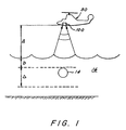
- the present invention relates to a remote sensing unit identified generally at 100 positioned on an airborne platform such as helicopter 30 and used for detecting and imaging targets and other objects 14 submerged in water 16 or obscured in conditions where atmospheric propagation of visible light is severely hampered by fog, dust, smoke, haze, snow and the like.
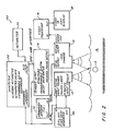
- the present invention generally comprises a pulsed laser 10 which operates at a wavelength which may either be visible or invisible to the human eye (more than 900 nm), a fast gated television camera 12, timing control electronics 14 for controlling laser 10 and camera 12, video processing unit 16, cathode ray tube (CRT) video display unit 18, altimeter 20 and computer 22.
- Light pulses are emitted from laser 10 (at 20 Hz rate in this embodiment) and the light is passed through a negative focal length lens (not shown) to expand the laser beam into a cone which illuminates a spot at the target scene 14 within medium 16 (water).
- the shutter of camera 12 is opened briefly after an appropriate delay time such that the image formed by the camera and lens is composed of light backscattered or reflected by the target scene.
- the video signals from the camera are then processed in video processing unit 16 and displayed on a cathode ray tube 18.
- the timing control of lidar system 100 relies upon a signal from the aircraft altimeter 20 to continually provide platform altitude information. Because the timing of the lidar system is under the control of computer 22, the altimeter signal can be interpreted and used to adjust total delay so as to automatically track changing platform altitude.
- Computer 22 is operatively connected to digital delay generator 14 by a bidirectional parallel interface such as IEEE-488, allowing the computer to set the time delay and width for each camera gating pulse.
- the ICCD camera 12 provides standard RS-170 video format output with one field updated every 1/60 second.
- An internally generated 60 Hz pulse train from camera 12 is frequency divided by a factor of 3 in divider 24 to provide a 20 Hz clock signal for system timing control.
- the 20 Hz signal is first used to fire the flash lamps in laser 10 and to trigger the fixes 210 microsecond delay generator 26, whose output pulse triggers the laser Q-switch to produce the narrow laser output pulse.
- the 20 Hz clock pulses trigger the programmable delay generator 14 and the hardware interrupt line input to computer 22.
- the computer 22 upon detecting the interrupt signal, performs the following operations. First, it reads the aircraft altitude by an analog-to-digital conversion of the input signal from altimeter 20.
- ⁇ water (2) (n water ) (D/c) (2)
- n water is the index of refraction of the medium 16 which is assumed here to be water
- D is the depth from FIGURE 1 of the upper edge of the submerged volume to be imaged.
- lidar system 100 objects at depths between D and D + ⁇ will be imaged by lidar system 100.
- the computer 22 sends digital commands to programmable delay generator 14 to set the timing delay and output pulse width (which is set to ⁇ defined above).
- the programmable delay time is set to the algebraic sum of ( ⁇ air) + ( ⁇ water) + (210 microsec fixed delay) + (laser Q-switch propagation delay) - (delay generator propagation delay) - (camera propagation delay).
- a system delay time constant which is the algebraic sum of the last four constant delays defined above, is actually empirically measured and stored in computer memory for this calculation.
- the nominal 210 microsecond lamp-to-laser delay easily allows time for all system delays while keeping the total delay requirement to a small fraction of a pulse. This results in a reduction of the number of delay generators required for camera gating control from two in prior U.S. Patent No 4,862,257 to only one in the present invention.
- Still another feature of the present invention is the elimination of the demanding stability requirement upon the master clock since pulse-to-pulse timing is no longer critical.
- FIGURE 2 The actual components depicted in FIGURE 2 are substantially similar or identical to the corresponding components described in detail in U.S. Patent 4,862,257 and EP-A2 0363735. Accordingly, reference should be made to the detailed descriptions of the pulsed laser 10, ICCD camera 12, Stanford digital delay generator 14, video processor 16 and CRT display 18 in the just cited patents for a more detailed description. Similarly, the present invention may utilize more than one camera 12 as described in U.S. Patent 4,862,257.
- computer 22 comprises a VME bus computer and fixed delay generator 26 comprises a AVX-D-3KS1A manufactured by Avtech Electrosystems.
- the present invention does require the presence of an altimeter on board the airborne platform; and that the altimeter be readable by computer 22. Fortunately, the added requirement for an altimeter signal readable by computer 22 is routinely fulfilled in most aircraft systems.
- the altimeter range of operation will determine the usable lidar system altitude range; and the resolution of the altimeter will determine accuracy of locating depth of observation.
- the lack of absolute accuracy as well as variance between altimeters can be compensated for with computer 22 following a calibration sequence.
Landscapes
- Physics & Mathematics (AREA)
- Engineering & Computer Science (AREA)
- Electromagnetism (AREA)
- Computer Networks & Wireless Communication (AREA)
- General Physics & Mathematics (AREA)
- Radar, Positioning & Navigation (AREA)
- Remote Sensing (AREA)
- Optical Radar Systems And Details Thereof (AREA)
- Radar Systems Or Details Thereof (AREA)
- Traffic Control Systems (AREA)
- Measurement Of Optical Distance (AREA)
Applications Claiming Priority (2)
| Application Number | Priority Date | Filing Date | Title |
|---|---|---|---|
| US07/420,247 US4964721A (en) | 1989-10-12 | 1989-10-12 | Imaging lidar system |
| US420247 | 1989-10-12 |
Publications (3)
| Publication Number | Publication Date |
|---|---|
| EP0422415A2 true EP0422415A2 (de) | 1991-04-17 |
| EP0422415A3 EP0422415A3 (en) | 1992-04-29 |
| EP0422415B1 EP0422415B1 (de) | 1995-11-02 |
Family
ID=23665683
Family Applications (1)
| Application Number | Title | Priority Date | Filing Date |
|---|---|---|---|
| EP90117892A Expired - Lifetime EP0422415B1 (de) | 1989-10-12 | 1990-09-18 | Verfahren und Gerät zur Bilderzeugung mittels LIDAR |
Country Status (10)
| Country | Link |
|---|---|
| US (1) | US4964721A (de) |
| EP (1) | EP0422415B1 (de) |
| JP (1) | JPH03148088A (de) |
| AT (1) | ATE129814T1 (de) |
| CA (1) | CA2021449A1 (de) |
| DE (1) | DE69023312T2 (de) |
| DK (1) | DK0422415T3 (de) |
| ES (1) | ES2079411T3 (de) |
| GR (1) | GR3018418T3 (de) |
| IL (1) | IL94985A0 (de) |
Cited By (2)
| Publication number | Priority date | Publication date | Assignee | Title |
|---|---|---|---|---|
| EP0494700A3 (en) * | 1991-10-11 | 1993-03-03 | Kaman Aerospace Corporation | Imaging lidar system for shallow and coastal water |
| US5243541A (en) * | 1991-10-11 | 1993-09-07 | Kaman Aerospace Corporation | Imaging lidar system for shallow and coastal water |
Families Citing this family (22)
| Publication number | Priority date | Publication date | Assignee | Title |
|---|---|---|---|---|
| US5034810A (en) * | 1989-12-07 | 1991-07-23 | Kaman Aerospace Corporation | Two wavelength in-situ imaging of solitary internal waves |
| US5276632A (en) * | 1990-08-10 | 1994-01-04 | Kaman Aerospace Corporation | Method and apparatus for improved visual display of a target viewed by an imaging sensor device |
| US5231401A (en) * | 1990-08-10 | 1993-07-27 | Kaman Aerospace Corporation | Imaging lidar system |
| US5267329A (en) * | 1990-08-10 | 1993-11-30 | Kaman Aerospace Corporation | Process for automatically detecting and locating a target from a plurality of two dimensional images |
| US5181135A (en) * | 1990-12-21 | 1993-01-19 | Kaman Aerospace Corporation | Optical underwater communications systems employing tunable and fixed frequency laser transmitters |
| US5270780A (en) * | 1991-09-13 | 1993-12-14 | Science Applications International Corporation | Dual detector lidar system and method |
| US5202741A (en) * | 1992-06-29 | 1993-04-13 | The United States Of America As Represented By The Department Of Energy | Active imaging system with Faraday filter |
| US5506616A (en) * | 1992-10-07 | 1996-04-09 | The United States Of America As Represented By The Secretary Of The Navy | Differential imaging for sensitive pattern recognition |
| US5379967A (en) * | 1993-04-30 | 1995-01-10 | State Of Israel Ministry Of Defense Armament Development Authority Rafael | Day/night optical guiding apparatus |
| US5448936A (en) | 1994-08-23 | 1995-09-12 | Hughes Aircraft Company | Destruction of underwater objects |
| US6963354B1 (en) * | 1997-08-07 | 2005-11-08 | The United States Of America As Represented By The Secretary Of The Navy | High resolution imaging lidar for detecting submerged objects |
| US6515737B2 (en) * | 2000-01-04 | 2003-02-04 | The Regents Of The University Of California | High-resolution imaging and target designation through clouds or smoke |
| US8994822B2 (en) | 2002-08-28 | 2015-03-31 | Visual Intelligence Lp | Infrastructure mapping system and method |
| US8483960B2 (en) | 2002-09-20 | 2013-07-09 | Visual Intelligence, LP | Self-calibrated, remote imaging and data processing system |
| US7893957B2 (en) | 2002-08-28 | 2011-02-22 | Visual Intelligence, LP | Retinal array compound camera system |
| US7212938B2 (en) * | 2002-09-17 | 2007-05-01 | M7 Visual Intelligence, Lp | Method of using a self-locking travel pattern to achieve calibration of remote sensors using conventionally collected data |
| USRE49105E1 (en) | 2002-09-20 | 2022-06-14 | Vi Technologies, Llc | Self-calibrated, remote imaging and data processing system |
| US8184276B2 (en) * | 2008-12-08 | 2012-05-22 | Carl Embry | Continuous index of refraction compensation method for measurements in a medium |
| US12399278B1 (en) | 2016-02-15 | 2025-08-26 | Red Creamery Llc | Hybrid LIDAR with optically enhanced scanned laser |
| US12399279B1 (en) | 2016-02-15 | 2025-08-26 | Red Creamery Llc | Enhanced hybrid LIDAR with high-speed scanning |
| US12123950B2 (en) | 2016-02-15 | 2024-10-22 | Red Creamery, LLC | Hybrid LADAR with co-planar scanning and imaging field-of-view |
| US11556000B1 (en) | 2019-08-22 | 2023-01-17 | Red Creamery Llc | Distally-actuated scanning mirror |
Family Cites Families (7)
| Publication number | Priority date | Publication date | Assignee | Title |
|---|---|---|---|---|
| US3446555A (en) * | 1964-02-18 | 1969-05-27 | Kollsman Instr Corp | Optical ranging and detection system for submerged objects |
| US3527533A (en) * | 1964-08-25 | 1970-09-08 | Trw Inc | Method and apparatus for deriving and processing topographical information |
| US3604803A (en) * | 1969-03-03 | 1971-09-14 | Kollsman Instr Corp | Optical detection method for submerged objects |
| US3669540A (en) * | 1970-08-31 | 1972-06-13 | Raytheon Co | Optical depth finder and elements therefor |
| NL159789B (nl) * | 1970-10-29 | 1979-03-15 | Siemens Ag | Optische afstandmeetinrichting. |
| US4277167A (en) * | 1976-08-25 | 1981-07-07 | The United States Of America As Represented By The Secretary Of The Navy | Depth mapping system |
| US4862257A (en) * | 1988-07-07 | 1989-08-29 | Kaman Aerospace Corporation | Imaging lidar system |
-
1989
- 1989-10-12 US US07/420,247 patent/US4964721A/en not_active Expired - Lifetime
-
1990
- 1990-07-05 IL IL94985A patent/IL94985A0/xx not_active IP Right Cessation
- 1990-07-18 CA CA002021449A patent/CA2021449A1/en not_active Abandoned
- 1990-09-18 AT AT90117892T patent/ATE129814T1/de not_active IP Right Cessation
- 1990-09-18 DK DK90117892.1T patent/DK0422415T3/da active
- 1990-09-18 EP EP90117892A patent/EP0422415B1/de not_active Expired - Lifetime
- 1990-09-18 DE DE69023312T patent/DE69023312T2/de not_active Expired - Fee Related
- 1990-09-18 ES ES90117892T patent/ES2079411T3/es not_active Expired - Lifetime
- 1990-10-11 JP JP2275111A patent/JPH03148088A/ja active Pending
-
1995
- 1995-12-15 GR GR950403540T patent/GR3018418T3/el unknown
Cited By (3)
| Publication number | Priority date | Publication date | Assignee | Title |
|---|---|---|---|---|
| EP0494700A3 (en) * | 1991-10-11 | 1993-03-03 | Kaman Aerospace Corporation | Imaging lidar system for shallow and coastal water |
| US5243541A (en) * | 1991-10-11 | 1993-09-07 | Kaman Aerospace Corporation | Imaging lidar system for shallow and coastal water |
| US5457639A (en) * | 1991-10-11 | 1995-10-10 | Kaman Aerospace Corporation | Imaging lidar system for shallow and coastal water |
Also Published As
| Publication number | Publication date |
|---|---|
| US4964721A (en) | 1990-10-23 |
| EP0422415A3 (en) | 1992-04-29 |
| DE69023312D1 (de) | 1995-12-07 |
| DE69023312T2 (de) | 1996-05-15 |
| EP0422415B1 (de) | 1995-11-02 |
| CA2021449A1 (en) | 1991-04-13 |
| ATE129814T1 (de) | 1995-11-15 |
| IL94985A0 (en) | 1991-06-10 |
| DK0422415T3 (da) | 1996-02-12 |
| GR3018418T3 (en) | 1996-03-31 |
| ES2079411T3 (es) | 1996-01-16 |
| JPH03148088A (ja) | 1991-06-24 |
Similar Documents
| Publication | Publication Date | Title |
|---|---|---|
| EP0422415B1 (de) | Verfahren und Gerät zur Bilderzeugung mittels LIDAR | |
| CA1332978C (en) | Imaging lidar system using non-visible light | |
| US7554652B1 (en) | Light-integrating rangefinding device and method | |
| US3947119A (en) | Active sensor automatic range sweep technique | |
| EP0378669B1 (de) | Bildformungs-lidarsystem | |
| US5034810A (en) | Two wavelength in-situ imaging of solitary internal waves | |
| US20090273770A1 (en) | Systems and methods for safe laser imaging, detection and ranging (lidar) operation | |
| US4967270A (en) | Lidar system incorporating multiple cameras for obtaining a plurality of subimages | |
| CA1186395A (en) | Ocean depth sounding from the air by laser beam | |
| US5233415A (en) | Imaging lidar employing transmitter referencing | |
| TWI432768B (zh) | 藉由光電影像感測器判定距離之方法與裝置 | |
| EP1595162B1 (de) | Laser-torgeschaltetes kameraabbildungssystem und verfahren | |
| US3604803A (en) | Optical detection method for submerged objects | |
| US4226529A (en) | Viewing systems | |
| JPH04301784A (ja) | 単一及び連続式フレームのためのマルチパルス単一及び多重ゲートを用いる画像ライダシステム | |
| EP2260325B1 (de) | Lichtintegrierende entfernungsbestimmungseinrichtung und verfahren | |
| NZ229854A (en) | Determining transmissivity and depth of water using pulsed laser | |
| US3446555A (en) | Optical ranging and detection system for submerged objects | |
| CN110673112A (zh) | 一种条纹管激光雷达距离选通门控制方法及装置 | |
| Andersen et al. | Submillimeter 3-D laser radar for space shuttle tile inspection | |
| JP3755216B2 (ja) | 形状計測装置及び方法 | |
| EP3508881A1 (de) | Lichtimpulse und detektoren zum empfangen in zeitfenstern | |
| Amagai et al. | 4.4 Timing System | |
| SU646806A1 (ru) | Устройство дл измерени дальности видимости объектов | |
| JPH07117358B2 (ja) | 誘導装置 |
Legal Events
| Date | Code | Title | Description |
|---|---|---|---|
| PUAI | Public reference made under article 153(3) epc to a published international application that has entered the european phase |
Free format text: ORIGINAL CODE: 0009012 |
|
| AK | Designated contracting states |
Kind code of ref document: A2 Designated state(s): AT BE CH DE DK ES FR GB GR IT LI LU NL SE |
|
| PUAL | Search report despatched |
Free format text: ORIGINAL CODE: 0009013 |
|
| AK | Designated contracting states |
Kind code of ref document: A3 Designated state(s): AT BE CH DE DK ES FR GB GR IT LI LU NL SE |
|
| 17P | Request for examination filed |
Effective date: 19920908 |
|
| 17Q | First examination report despatched |
Effective date: 19940531 |
|
| GRAA | (expected) grant |
Free format text: ORIGINAL CODE: 0009210 |
|
| AK | Designated contracting states |
Kind code of ref document: B1 Designated state(s): AT BE CH DE DK ES FR GB GR IT LI LU NL SE |
|
| REF | Corresponds to: |
Ref document number: 129814 Country of ref document: AT Date of ref document: 19951115 Kind code of ref document: T |
|
| REF | Corresponds to: |
Ref document number: 69023312 Country of ref document: DE Date of ref document: 19951207 |
|
| ET | Fr: translation filed | ||
| ITF | It: translation for a ep patent filed | ||
| REG | Reference to a national code |
Ref country code: ES Ref legal event code: FG2A Ref document number: 2079411 Country of ref document: ES Kind code of ref document: T3 |
|
| REG | Reference to a national code |
Ref country code: CH Ref legal event code: NV Representative=s name: PATENTANWALTSBUERO EDER AG |
|
| REG | Reference to a national code |
Ref country code: DK Ref legal event code: T3 |
|
| REG | Reference to a national code |
Ref country code: GR Ref legal event code: FG4A Free format text: 3018418 |
|
| PGFP | Annual fee paid to national office [announced via postgrant information from national office to epo] |
Ref country code: LU Payment date: 19960801 Year of fee payment: 7 |
|
| PGFP | Annual fee paid to national office [announced via postgrant information from national office to epo] |
Ref country code: FR Payment date: 19960814 Year of fee payment: 7 |
|
| PGFP | Annual fee paid to national office [announced via postgrant information from national office to epo] |
Ref country code: SE Payment date: 19960819 Year of fee payment: 7 Ref country code: DK Payment date: 19960819 Year of fee payment: 7 |
|
| PGFP | Annual fee paid to national office [announced via postgrant information from national office to epo] |
Ref country code: NL Payment date: 19960820 Year of fee payment: 7 Ref country code: DE Payment date: 19960820 Year of fee payment: 7 |
|
| PGFP | Annual fee paid to national office [announced via postgrant information from national office to epo] |
Ref country code: AT Payment date: 19960821 Year of fee payment: 7 |
|
| PGFP | Annual fee paid to national office [announced via postgrant information from national office to epo] |
Ref country code: CH Payment date: 19960823 Year of fee payment: 7 |
|
| PGFP | Annual fee paid to national office [announced via postgrant information from national office to epo] |
Ref country code: BE Payment date: 19960827 Year of fee payment: 7 |
|
| PGFP | Annual fee paid to national office [announced via postgrant information from national office to epo] |
Ref country code: GB Payment date: 19960828 Year of fee payment: 7 |
|
| PGFP | Annual fee paid to national office [announced via postgrant information from national office to epo] |
Ref country code: GR Payment date: 19960829 Year of fee payment: 7 |
|
| PLBE | No opposition filed within time limit |
Free format text: ORIGINAL CODE: 0009261 |
|
| STAA | Information on the status of an ep patent application or granted ep patent |
Free format text: STATUS: NO OPPOSITION FILED WITHIN TIME LIMIT |
|
| PGFP | Annual fee paid to national office [announced via postgrant information from national office to epo] |
Ref country code: ES Payment date: 19960917 Year of fee payment: 7 |
|
| 26N | No opposition filed | ||
| PG25 | Lapsed in a contracting state [announced via postgrant information from national office to epo] |
Ref country code: LU Free format text: LAPSE BECAUSE OF NON-PAYMENT OF DUE FEES Effective date: 19970918 Ref country code: GB Free format text: LAPSE BECAUSE OF NON-PAYMENT OF DUE FEES Effective date: 19970918 Ref country code: DK Free format text: LAPSE BECAUSE OF NON-PAYMENT OF DUE FEES Effective date: 19970918 Ref country code: AT Free format text: LAPSE BECAUSE OF NON-PAYMENT OF DUE FEES Effective date: 19970918 |
|
| REG | Reference to a national code |
Ref country code: DK Ref legal event code: EBP |
|
| PG25 | Lapsed in a contracting state [announced via postgrant information from national office to epo] |
Ref country code: SE Free format text: LAPSE BECAUSE OF NON-PAYMENT OF DUE FEES Effective date: 19970919 Ref country code: ES Free format text: LAPSE BECAUSE OF THE APPLICANT RENOUNCES Effective date: 19970919 |
|
| PG25 | Lapsed in a contracting state [announced via postgrant information from national office to epo] |
Ref country code: LI Free format text: LAPSE BECAUSE OF NON-PAYMENT OF DUE FEES Effective date: 19970930 Ref country code: GR Free format text: LAPSE BECAUSE OF NON-PAYMENT OF DUE FEES Effective date: 19970930 Ref country code: FR Free format text: THE PATENT HAS BEEN ANNULLED BY A DECISION OF A NATIONAL AUTHORITY Effective date: 19970930 Ref country code: CH Free format text: LAPSE BECAUSE OF NON-PAYMENT OF DUE FEES Effective date: 19970930 Ref country code: BE Free format text: LAPSE BECAUSE OF NON-PAYMENT OF DUE FEES Effective date: 19970930 |
|
| BERE | Be: lapsed |
Owner name: KAMAN AEROSPACE CORP. Effective date: 19970930 |
|
| PG25 | Lapsed in a contracting state [announced via postgrant information from national office to epo] |
Ref country code: NL Free format text: LAPSE BECAUSE OF NON-PAYMENT OF DUE FEES Effective date: 19980401 |
|
| GBPC | Gb: european patent ceased through non-payment of renewal fee |
Effective date: 19970918 |
|
| REG | Reference to a national code |
Ref country code: CH Ref legal event code: PL |
|
| NLV4 | Nl: lapsed or anulled due to non-payment of the annual fee |
Effective date: 19980401 |
|
| PG25 | Lapsed in a contracting state [announced via postgrant information from national office to epo] |
Ref country code: DE Free format text: LAPSE BECAUSE OF NON-PAYMENT OF DUE FEES Effective date: 19980603 |
|
| EUG | Se: european patent has lapsed |
Ref document number: 90117892.1 |
|
| REG | Reference to a national code |
Ref country code: FR Ref legal event code: ST |
|
| REG | Reference to a national code |
Ref country code: ES Ref legal event code: FD2A Effective date: 20001009 |
|
| PG25 | Lapsed in a contracting state [announced via postgrant information from national office to epo] |
Ref country code: IT Free format text: LAPSE BECAUSE OF NON-PAYMENT OF DUE FEES;WARNING: LAPSES OF ITALIAN PATENTS WITH EFFECTIVE DATE BEFORE 2007 MAY HAVE OCCURRED AT ANY TIME BEFORE 2007. THE CORRECT EFFECTIVE DATE MAY BE DIFFERENT FROM THE ONE RECORDED. Effective date: 20050918 |