EP0422431A2 - Dispositif à diversité angulaire - Google Patents
Dispositif à diversité angulaire Download PDFInfo
- Publication number
- EP0422431A2 EP0422431A2 EP90118209A EP90118209A EP0422431A2 EP 0422431 A2 EP0422431 A2 EP 0422431A2 EP 90118209 A EP90118209 A EP 90118209A EP 90118209 A EP90118209 A EP 90118209A EP 0422431 A2 EP0422431 A2 EP 0422431A2
- Authority
- EP
- European Patent Office
- Prior art keywords
- wave
- waveguide
- type
- wave type
- polarization
- Prior art date
- Legal status (The legal status is an assumption and is not a legal conclusion. Google has not performed a legal analysis and makes no representation as to the accuracy of the status listed.)
- Granted
Links
- 230000005855 radiation Effects 0.000 claims abstract description 31
- 238000000034 method Methods 0.000 claims abstract description 19
- 230000010287 polarization Effects 0.000 claims description 31
- 230000005284 excitation Effects 0.000 claims description 10
- 230000007704 transition Effects 0.000 claims description 7
- 238000010586 diagram Methods 0.000 claims description 4
- 238000005388 cross polarization Methods 0.000 claims description 2
- 230000000694 effects Effects 0.000 claims description 2
- 230000001939 inductive effect Effects 0.000 claims description 2
- IHQKEDIOMGYHEB-UHFFFAOYSA-M sodium dimethylarsinate Chemical class [Na+].C[As](C)([O-])=O IHQKEDIOMGYHEB-UHFFFAOYSA-M 0.000 claims description 2
- 230000009466 transformation Effects 0.000 description 3
- 230000006978 adaptation Effects 0.000 description 1
- 230000008033 biological extinction Effects 0.000 description 1
- 230000005540 biological transmission Effects 0.000 description 1
- 238000011161 development Methods 0.000 description 1
- 230000018109 developmental process Effects 0.000 description 1
- 238000005562 fading Methods 0.000 description 1
- 238000005192 partition Methods 0.000 description 1
- 230000000704 physical effect Effects 0.000 description 1
- 230000001902 propagating effect Effects 0.000 description 1
Images

Classifications
-
- H—ELECTRICITY
- H01—ELECTRIC ELEMENTS
- H01Q—ANTENNAS, i.e. RADIO AERIALS
- H01Q21/00—Antenna arrays or systems
- H01Q21/24—Combinations of antenna units polarised in different directions for transmitting or receiving circularly and elliptically polarised waves or waves linearly polarised in any direction
-
- H—ELECTRICITY
- H01—ELECTRIC ELEMENTS
- H01Q—ANTENNAS, i.e. RADIO AERIALS
- H01Q25/00—Antennas or antenna systems providing at least two radiating patterns
- H01Q25/04—Multimode antennas
Definitions
- An angle diversity method is known from EP 0 061 576 B1, for example, which is based on the multi-mode principle.
- the excitation horn of the Antenna feeding system of signals which reach the receiving antenna from a main direction of propagation, excites symmetrical wave types, and signals, which spread through detours, excite waves with an antisymmetric field distribution.
- a mode coupler belonging to the antenna feed system separates these different wave types, and a selection receiver derives an optimal reception signal from them.
- this selection receiver contains a combiner (for example in the HF or IF level) which forms a best signal from both signals.
- the invention is based on the object of specifying an angular diversity method of the type mentioned at the outset which, in the case of multipath propagation in a radio field, enables the transmitted signals to be received with a low frequency of errors.
- Such antisymmetric wave types can be, for example, the H20 wave type and a wave type resulting from the superimposition of an H11 and an E11 wave.
- the superposition of the H11 and E11 wave types should be such that there is a field extinction in the polarization direction of the H20 wave type and a field strength addition occurs in the orthogonal polarization direction.
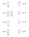
- the previously mentioned wave types excited in the exciter horn and / or in the waveguide transition 3 - these are the H01, H11, E11, H10 and H20 wave types - have the multi-type inputs on the exciter horn side Waveguide branch 2 the field states shown in FIGS. 2a, 3a, 4a and 5a.
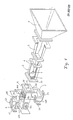
- the multi-type waveguide branch 2 designed as a rectangular waveguide, is divided at one end into two partial waveguides by a separating plate 7, which runs parallel to the narrow waveguide sides and is guided in grooves 8 in the broad waveguide sides.
- a waveguide 41, 42 designed as a polarization switch is connected to each of these partial waveguides of the multi-type waveguide branch 2.
- Each of the two waveguides 41 and 42 is provided with two outlets 411, 412 and 421, 422 which are arranged one behind the other and are rotated by 90 ° with respect to one another.
- the two waveguides 41 and 42 designed as polarization switches are arranged directly next to one another and separated from one another by a common wall 43. This creates a very compact arrangement, referred to here as a double polarization switch 4.
- the wave types propagating in the multi-type waveguide branch 2, the field states of which prevail at the exciter end show FIGS. 2a, 3a, 4a and 5a, take in the partial waveguides created by the separating plate 7 those in FIGS. 2b, 3b, 4b and 5b shown field states.
- the H01 wave type (FIG. 2a) in the two partial waveguides is divided into two vertically polarized, in-phase waves (FIG. 2b).
- the wave created by superimposing the H11 and the E11 wave type (FIG. 3a) is divided into two antiphase, vertically polarized waves (FIG. 3b) by the separating plate 7 in the two partial waveguides.
- the H10 wave type (FIG. 4a) merges in the two partial waveguides on both sides of the separating plate 7 into two in-phase, horizontally polarized waves (FIG. 4b).
- the H20 wave type (FIG. 5a) is divided by the separating plate 7 into two waves which are polarized in the horizontal direction and are in opposite phases (FIG. 5b).
- the following wave types can then be tapped from the outputs 411, 412, 421 and 422 of the double polarization switch 4 coupled to the multi-type waveguide branch 2.
- the field energy components of the H01 and the wave type resulting from the superimposition of the H11 and E11 waves originating from one of the two partial waveguides of the multi-type waveguide branch 2 are available.
- the energy components of the same wave types originating from the other partial waveguide can be tapped off at the output 421 of the other waveguide 42.
- the output 412 of the waveguide 41 supplies the field energy components of the H10 wave type and the H20 wave type originating from one of the two partial waveguides of the multi-type waveguide branch 2.
- the entire field energy of the horizontally polarized H01 wave can be tapped off at gate 53 - the so-called E-gate - of the series parallel junction 5 (magic T), and at gate 54 - the so-called H-gate - the entire field energy is available to that wave Available, which resulted from the superposition of the H11 and E11 waves.
- the gates 612 and 622 are coupled to the outputs 412 and 422 of the double polarization switch 4 from the second series parallel branch 6.
- a diversity receiver of a known type derives an optimal reception signal from the waves available at gates 53, 54, 63 and 64 of the two series parallel branches 5 and 6.
- the separating plate 7 used in the multi-type waveguide branch 2 is provided on its end face pointing into the interior of the waveguide with a pin 9 which is oriented in the direction of wave propagation.
- This pin 9 has an influence on the H11 and E11 shaft types.
- the length of the pin 9 is selected so that there is a phase overlap of the H11 and E11 shaft types. Its length is approximately 1/8 of the waveguide wavelength of these two types of wave. 1 that the pin 9 is provided with a cross-sectional jump to implement a transformation stage.
- a further transformation stage can be formed by the partition plate 7 in the multi-type waveguide branch 2 with the waveguide wall 43 of the double polarization switch 4 separating the two waveguides 41 and 42.
- tuning pins are then to be arranged in front of the front end face of the separating plate 7 at a distance of approximately 3/4 of the waveguide wavelength for the basic wave type.
- Inductive effects of the separating plate 7 on the H10 and H20 shaft types can be compensated for by tuning pins in the broad sides of the waveguide 2.
- tuning pins for the basic wave type in front of the front end face of the separating plate 7 at a distance of half and at a distance of an entire waveguide wavelength.
- Tuning pins are to be arranged in a known manner where the wave type to be influenced has its field maximum.
- the cross-sectional adaptation taking place in the waveguide transition 3 from the rectangular exciter horn 1 to the rectangular waveguide of the multi-type waveguide branch 2 takes place continuously.
- the cross-sectional deformation takes place within the waveguide transition 3 in the E and H planes differently, and in such a way that in this waveguide transition 3 further higher wave types are excited (e.g. H30, H03, H12, E12).
- Overlaying these higher wave types with the symmetrical basic wave type (H10, H01) creates an approximately rotationally symmetrical excitation radiation diagram with little cross polarization.
- the continuous cross-sectional expansion is carried out at the same time in such a way that, with a short overall length in both polarizations, very good reflection behavior is achieved over a broad band.
- the antenna feed system described above is advantageously used in a double reflector antenna with a parabolic main reflector HR and an elliptical sub-reflector SR.
- the geometry of this double reflector antenna is designed so that, according to the geometric optics, a distortion-free representation of the excitation radiation diagram, consisting of the main radiation lobe HK and the spread secondary radiation lobe NK, is ensured in the antenna aperture. 1 is installed in the double reflector antenna in such a way that the vertical polarization in the radiation field of the antenna is assigned to the H01 wave (cf. FIG. 2a).
Landscapes
- Variable-Direction Aerials And Aerial Arrays (AREA)
- Waveguide Aerials (AREA)
- Mobile Radio Communication Systems (AREA)
- Radio Transmission System (AREA)
- Input Circuits Of Receivers And Coupling Of Receivers And Audio Equipment (AREA)
- Apparatus For Radiation Diagnosis (AREA)
- Control Of Motors That Do Not Use Commutators (AREA)
- Table Devices Or Equipment (AREA)
Applications Claiming Priority (2)
| Application Number | Priority Date | Filing Date | Title |
|---|---|---|---|
| DE3933683 | 1989-10-09 | ||
| DE3933683 | 1989-10-09 |
Publications (3)
| Publication Number | Publication Date |
|---|---|
| EP0422431A2 true EP0422431A2 (fr) | 1991-04-17 |
| EP0422431A3 EP0422431A3 (en) | 1991-12-18 |
| EP0422431B1 EP0422431B1 (fr) | 1996-12-27 |
Family
ID=6391116
Family Applications (1)
| Application Number | Title | Priority Date | Filing Date |
|---|---|---|---|
| EP90118209A Expired - Lifetime EP0422431B1 (fr) | 1989-10-09 | 1990-09-21 | Dispositif à diversité angulaire |
Country Status (3)
| Country | Link |
|---|---|
| EP (1) | EP0422431B1 (fr) |
| AT (1) | ATE146907T1 (fr) |
| DE (1) | DE59010617D1 (fr) |
Cited By (6)
| Publication number | Priority date | Publication date | Assignee | Title |
|---|---|---|---|---|
| EP0575788A1 (fr) * | 1992-06-26 | 1993-12-29 | Siemens Aktiengesellschaft | Lanceur multimode XPD-optimisé pour diversité d'angle |
| DE4326824A1 (de) * | 1993-08-10 | 1995-02-16 | Siemens Ag | Hohlleiterschaltung mit zwei Polarisationsweichen |
| US5821906A (en) * | 1993-04-30 | 1998-10-13 | Thomson-Csf | Rear feed source for reflector antenna |
| RU2124254C1 (ru) * | 1996-09-17 | 1998-12-27 | Акционерное общество открытого типа Научно-исследовательский институт радиоэлектронных систем Акционерного общества "Ленинец-Холдинг" | Облучающее устройство |
| RU2380804C1 (ru) * | 2008-08-04 | 2010-01-27 | Государственное унитарное предприятие "Конструкторское бюро приборостроения" | Моноимпульсный облучатель |
| DE102013011651A1 (de) * | 2013-07-11 | 2015-01-15 | ESA-microwave service GmbH | Antennen-Speisesystem im Mikrowellenbereich für Reflektorantennen |
Families Citing this family (1)
| Publication number | Priority date | Publication date | Assignee | Title |
|---|---|---|---|---|
| RU2236728C1 (ru) * | 2003-05-05 | 2004-09-20 | ОАО "НИИ Приборостроения им. В.В. Тихомирова" | Моноимпульсный облучатель |
Family Cites Families (3)
| Publication number | Priority date | Publication date | Assignee | Title |
|---|---|---|---|---|
| DE2626925C3 (de) * | 1976-06-16 | 1981-01-08 | Licentia Patent-Verwaltungs-Gmbh, 6000 Frankfurt | Verfahren zum Ausgleich von Ausbreitungsschwankungen bei Nachrichtenübertragungssystemen |
| DE3111731A1 (de) * | 1981-03-25 | 1982-10-14 | Licentia Patent-Verwaltungs-Gmbh, 6000 Frankfurt | Mikrowellenuebertragungseinrichtung mit mehrmodendiversity-kombinationsempfang |
| DE3604431A1 (de) * | 1986-02-13 | 1987-08-20 | Licentia Gmbh | Modenkoppler fuer monopulsanwendungen |
-
1990
- 1990-09-21 AT AT90118209T patent/ATE146907T1/de not_active IP Right Cessation
- 1990-09-21 DE DE59010617T patent/DE59010617D1/de not_active Expired - Fee Related
- 1990-09-21 EP EP90118209A patent/EP0422431B1/fr not_active Expired - Lifetime
Cited By (6)
| Publication number | Priority date | Publication date | Assignee | Title |
|---|---|---|---|---|
| EP0575788A1 (fr) * | 1992-06-26 | 1993-12-29 | Siemens Aktiengesellschaft | Lanceur multimode XPD-optimisé pour diversité d'angle |
| US5821906A (en) * | 1993-04-30 | 1998-10-13 | Thomson-Csf | Rear feed source for reflector antenna |
| DE4326824A1 (de) * | 1993-08-10 | 1995-02-16 | Siemens Ag | Hohlleiterschaltung mit zwei Polarisationsweichen |
| RU2124254C1 (ru) * | 1996-09-17 | 1998-12-27 | Акционерное общество открытого типа Научно-исследовательский институт радиоэлектронных систем Акционерного общества "Ленинец-Холдинг" | Облучающее устройство |
| RU2380804C1 (ru) * | 2008-08-04 | 2010-01-27 | Государственное унитарное предприятие "Конструкторское бюро приборостроения" | Моноимпульсный облучатель |
| DE102013011651A1 (de) * | 2013-07-11 | 2015-01-15 | ESA-microwave service GmbH | Antennen-Speisesystem im Mikrowellenbereich für Reflektorantennen |
Also Published As
| Publication number | Publication date |
|---|---|
| EP0422431B1 (fr) | 1996-12-27 |
| ATE146907T1 (de) | 1997-01-15 |
| DE59010617D1 (de) | 1997-02-06 |
| EP0422431A3 (en) | 1991-12-18 |
Similar Documents
| Publication | Publication Date | Title |
|---|---|---|
| DE69715518T2 (de) | Antennenspeiseeinrichtung für mehrere Frequenzen | |
| EP0061576A1 (fr) | Dispositif de transmission d'informations à micro-ondes avec réception combinée de diversité multimode | |
| DE2443166B2 (de) | Systemweiche zur trennung zweier signale, die aus je zwei doppelt polarisierten frequenzbaendern bestehen | |
| DE2502531A1 (de) | Antennenanordnung | |
| EP0041077B1 (fr) | Dispositif d'alimentation d'antenne pour une antenne de poursuite | |
| EP0422431B1 (fr) | Dispositif à diversité angulaire | |
| DE3786664T2 (de) | Mikrowellenerreger für orthogonal polarisierte wellen. | |
| DE68918426T2 (de) | Doppelfrequenz strahlende Vorrichtung. | |
| EP0128970A1 (fr) | Circuit à quatre accès pour une antenne de poursuite monopulse à microondes | |
| DE102008044895B4 (de) | Signal-Verzweigung zur Verwendung in einem Kommunikationssystem | |
| DE2810483C2 (de) | Antenne mit einem Schlitze aufweisenden Speisehohlleiter und einer mit diesem einen Winkel einschließenden Strahlerzeile | |
| DE2946331A1 (de) | Mikrowellen-leistungsteiler mit zwei eingaengen und drei ausgaengen | |
| DE1107736B (de) | Hornstrahler mit rechteckigem Querschnitt fuer Mikrowellen | |
| DE2719283C2 (de) | Antennenspeisesystem für Doppelpolarisation | |
| WO1999004282A1 (fr) | Dispositif pour emettre et recevoir des ondes radar, notamment pour un capteur de distance | |
| DE2626926C2 (de) | Hohlleiterprimärstrahler mit rechteckigem Querschnitt für eine Reflektorantenne mit Strahlschwenkung | |
| EP0419892B1 (fr) | Filtre de polarisation aux micro-ondes | |
| DE2625062A1 (de) | Phasenschieber zur verwendung bei einer elektronisch phasengesteuerten antenne | |
| DE2737125A1 (de) | Uebertragungsleitungssystem | |
| DE102017112441B4 (de) | Beamforming-Struktur, Antennenanordnung mit einer Beamforming-Struktur sowie Sende- und/oder Empfangsvorrichtung mit einer Beamforming-Struktur | |
| DE2747632A1 (de) | Antennenspeisesystem fuer doppelpolarisation | |
| DE2613592C3 (de) | Breitbandige Polarisationsweiche | |
| DE3336452C2 (fr) | ||
| EP0140199B1 (fr) | Dispositif pour compenser les composantes de polarisation croisée dans une antenne à réflecteur courbe et source primaire décentrée | |
| DE2135611B1 (de) | Modenkoppler für Peilsysteme |
Legal Events
| Date | Code | Title | Description |
|---|---|---|---|
| PUAI | Public reference made under article 153(3) epc to a published international application that has entered the european phase |
Free format text: ORIGINAL CODE: 0009012 |
|
| AK | Designated contracting states |
Kind code of ref document: A2 Designated state(s): AT CH DE GB LI NL SE |
|
| PUAL | Search report despatched |
Free format text: ORIGINAL CODE: 0009013 |
|
| AK | Designated contracting states |
Kind code of ref document: A3 Designated state(s): AT CH DE GB LI NL SE |
|
| 17P | Request for examination filed |
Effective date: 19911114 |
|
| 17Q | First examination report despatched |
Effective date: 19931116 |
|
| GRAG | Despatch of communication of intention to grant |
Free format text: ORIGINAL CODE: EPIDOS AGRA |
|
| RAP1 | Party data changed (applicant data changed or rights of an application transferred) |
Owner name: ROBERT BOSCH GMBH |
|
| GRAH | Despatch of communication of intention to grant a patent |
Free format text: ORIGINAL CODE: EPIDOS IGRA |
|
| GRAH | Despatch of communication of intention to grant a patent |
Free format text: ORIGINAL CODE: EPIDOS IGRA |
|
| GRAA | (expected) grant |
Free format text: ORIGINAL CODE: 0009210 |
|
| AK | Designated contracting states |
Kind code of ref document: B1 Designated state(s): AT CH DE GB LI NL SE |
|
| REF | Corresponds to: |
Ref document number: 146907 Country of ref document: AT Date of ref document: 19970115 Kind code of ref document: T |
|
| REG | Reference to a national code |
Ref country code: CH Ref legal event code: NV Representative=s name: SCINTILLA AG, DIREKTION |
|
| REF | Corresponds to: |
Ref document number: 59010617 Country of ref document: DE Date of ref document: 19970206 |
|
| GBT | Gb: translation of ep patent filed (gb section 77(6)(a)/1977) |
Effective date: 19970226 |
|
| PLBE | No opposition filed within time limit |
Free format text: ORIGINAL CODE: 0009261 |
|
| STAA | Information on the status of an ep patent application or granted ep patent |
Free format text: STATUS: NO OPPOSITION FILED WITHIN TIME LIMIT |
|
| 26N | No opposition filed | ||
| PG25 | Lapsed in a contracting state [announced via postgrant information from national office to epo] |
Ref country code: NL Free format text: LAPSE BECAUSE OF NON-PAYMENT OF DUE FEES Effective date: 19980401 |
|
| NLV4 | Nl: lapsed or anulled due to non-payment of the annual fee |
Effective date: 19980401 |
|
| PGFP | Annual fee paid to national office [announced via postgrant information from national office to epo] |
Ref country code: GB Payment date: 20000817 Year of fee payment: 11 |
|
| PGFP | Annual fee paid to national office [announced via postgrant information from national office to epo] |
Ref country code: DE Payment date: 20000911 Year of fee payment: 11 |
|
| PGFP | Annual fee paid to national office [announced via postgrant information from national office to epo] |
Ref country code: SE Payment date: 20000925 Year of fee payment: 11 |
|
| PGFP | Annual fee paid to national office [announced via postgrant information from national office to epo] |
Ref country code: CH Payment date: 20000927 Year of fee payment: 11 |
|
| PGFP | Annual fee paid to national office [announced via postgrant information from national office to epo] |
Ref country code: AT Payment date: 20001011 Year of fee payment: 11 |
|
| PG25 | Lapsed in a contracting state [announced via postgrant information from national office to epo] |
Ref country code: GB Free format text: LAPSE BECAUSE OF NON-PAYMENT OF DUE FEES Effective date: 20010921 Ref country code: AT Free format text: LAPSE BECAUSE OF NON-PAYMENT OF DUE FEES Effective date: 20010921 |
|
| PG25 | Lapsed in a contracting state [announced via postgrant information from national office to epo] |
Ref country code: SE Free format text: LAPSE BECAUSE OF NON-PAYMENT OF DUE FEES Effective date: 20010922 |
|
| PG25 | Lapsed in a contracting state [announced via postgrant information from national office to epo] |
Ref country code: LI Free format text: LAPSE BECAUSE OF NON-PAYMENT OF DUE FEES Effective date: 20010930 Ref country code: CH Free format text: LAPSE BECAUSE OF NON-PAYMENT OF DUE FEES Effective date: 20010930 |
|
| REG | Reference to a national code |
Ref country code: GB Ref legal event code: IF02 |
|
| PG25 | Lapsed in a contracting state [announced via postgrant information from national office to epo] |
Ref country code: DE Free format text: LAPSE BECAUSE OF NON-PAYMENT OF DUE FEES Effective date: 20020501 |
|
| EUG | Se: european patent has lapsed |
Ref document number: 90118209.7 |
|
| GBPC | Gb: european patent ceased through non-payment of renewal fee |
Effective date: 20010921 |
|
| REG | Reference to a national code |
Ref country code: CH Ref legal event code: PL |