EP0422521A1 - Filterpresse - Google Patents
Filterpresse Download PDFInfo
- Publication number
- EP0422521A1 EP0422521A1 EP90119153A EP90119153A EP0422521A1 EP 0422521 A1 EP0422521 A1 EP 0422521A1 EP 90119153 A EP90119153 A EP 90119153A EP 90119153 A EP90119153 A EP 90119153A EP 0422521 A1 EP0422521 A1 EP 0422521A1
- Authority
- EP
- European Patent Office
- Prior art keywords
- filter
- plate
- cloths
- rods
- shaking
- Prior art date
- Legal status (The legal status is an assumption and is not a legal conclusion. Google has not performed a legal analysis and makes no representation as to the accuracy of the status listed.)
- Granted
Links
- 239000004744 fabric Substances 0.000 claims abstract description 29
- 239000012065 filter cake Substances 0.000 claims abstract description 17
- 239000000725 suspension Substances 0.000 claims description 6
- 239000000463 material Substances 0.000 description 3
- 238000000034 method Methods 0.000 description 3
- 230000000694 effects Effects 0.000 description 2
- 230000001934 delay Effects 0.000 description 1
- 238000004519 manufacturing process Methods 0.000 description 1
- 239000012528 membrane Substances 0.000 description 1
- 238000007790 scraping Methods 0.000 description 1
- 230000035939 shock Effects 0.000 description 1
- 239000007787 solid Substances 0.000 description 1
Images


Classifications
-
- B—PERFORMING OPERATIONS; TRANSPORTING
- B01—PHYSICAL OR CHEMICAL PROCESSES OR APPARATUS IN GENERAL
- B01D—SEPARATION
- B01D25/00—Filters formed by clamping together several filtering elements or parts of such elements
- B01D25/12—Filter presses, i.e. of the plate or plate and frame type
- B01D25/127—Filter presses, i.e. of the plate or plate and frame type with one or more movable filter bands arranged to be clamped between the press plates or between a plate and a frame during filtration, e.g. zigzag endless filter bands
-
- B—PERFORMING OPERATIONS; TRANSPORTING
- B01—PHYSICAL OR CHEMICAL PROCESSES OR APPARATUS IN GENERAL
- B01D—SEPARATION
- B01D25/00—Filters formed by clamping together several filtering elements or parts of such elements
- B01D25/28—Leaching or washing filter cakes in the filter handling the filter cake for purposes other than regenerating
- B01D25/282—Leaching or washing filter cakes in the filter handling the filter cake for purposes other than regenerating for drying
- B01D25/285—Leaching or washing filter cakes in the filter handling the filter cake for purposes other than regenerating for drying by compression using inflatable membranes
-
- B—PERFORMING OPERATIONS; TRANSPORTING
- B01—PHYSICAL OR CHEMICAL PROCESSES OR APPARATUS IN GENERAL
- B01D—SEPARATION
- B01D25/00—Filters formed by clamping together several filtering elements or parts of such elements
- B01D25/32—Removal of the filter cakes
- B01D25/34—Removal of the filter cakes by moving, e.g. rotating, the filter elements
- B01D25/346—Removal of the filter cakes by moving, e.g. rotating, the filter elements by vibration
Definitions
- the invention relates to a filter press with a filter plate package suspended from the upper guide rails, in which the filter plates are covered on both sides with filter cloths, and to a plate transport slide that can be moved along the guide rails.
- Such filter presses are e.g. B. known from DE-PS 29 23 864.
- the filter plates are successively pulled off the filter plate pack for the purpose of filter cake ejection, so that the filter cake spaces are released for a cake ejection at the individual plate. Since the filter cakes often adhere strongly to the filter cloths, it is known to provide such filter presses with a device for scraping the filter cake, cf. e.g. B. DE-OS 36 08 774.
- the use of such scraper devices delays the filter press operation and, depending on the filter cake material, the scraper can also lead to undesirable solid smearing of the filter cloths.
- the invention has for its object to equip the generic filter press with a device for supporting the filter cake ejection, which works very effectively and should be characterized by a low manufacturing cost and space requirements.
- the filter press according to the invention is characterized by a shaking device arranged on the plate transport carriage for shaking the filter cloths for the purpose of ejecting the filter cake, the shaking movement being predominantly directed perpendicular to the filter cloth plane.
- a shaking device arranged on the plate transport carriage for shaking the filter cloths for the purpose of ejecting the filter cake, the shaking movement being predominantly directed perpendicular to the filter cloth plane.
- a further advantage is that the arrangement of the shaking device on the plate transport carriage automatically results in a correct alignment of the shaking device with the filter cloths that are being prepared for a filter cake ejection, so that special control and positioning devices are unnecessary.
- the shaking device can be integrated into the plate transport slide without requiring additional space.
- the filter cloths are each attached to rods at the top, that with each filter plate the two filter cloth rods are loosely supported at the ends by means of pivot levers on an axis extending above the upper edge of the filter plate, which are on the Filter plate suspension is attached so that in the filter plate, which is isolated for the purpose of ejecting the cake, the two filter cloths can be pivoted away from the filter plate against spring force into an inclined bearing that the shaking device on the Has plate transport carriage arranged adjusting cylinders which are each aligned in their working position on one end of a pivotally mounted on the axis double lever, which carries one of the filter cloth rods at its other end.
- the adjustment cylinders On the first part of their piston downward movement, the adjustment cylinders first cause the filter cloths to be inclined, and then they can shake the filter cloth with short, rapid strokes.
- the adjustment cylinders therefore have a double task in this way of working.
- they On the one hand, they cause the filter cloths to be inclined, which already promotes the filter cake ejection, and on the other hand they perform a vibration-like shaking movement on the inclined filter cloths, for example, to detach filter cake residues still adhering to the island from the filter cloth.
- the adjusting cylinders can carry out their full stroke in rapid repetition each time, so that the filter cloths undergo an extensive shaking movement.
- the pairs of swivel levers arranged at both ends of the filter cloth rods are loaded in the direction of the filter plate by a tension spring arranged between them in such a way that the upper filter cloth edges, when the filter plate package is closed, inwards around the upper corners of the filter plate are strung around.
- a plurality of filter plates 3 are movably suspended from two I-guide rails 1, 2 extending over the length of the filter press, of which only one filter plate is shown with its upper region in the figures.
- the filter plates 3 each consist of a support plate 5 provided with a recess, a so-called filter mirror 4, on the flat side of which a press membrane 6 is clamped by means of a frame 7.
- a generally approximately U-shaped suspension yoke 8 is attached, to which two upwardly projecting suspension arms 9, 10 are attached, which carry rollers 11 which run on special guide profiles 12, which in turn are on the lower inner legs of the I- Guide rails 1, 2 are attached.
- a plate transport carriage 13 On these lower inner legs of the rails 1, 2, a plate transport carriage 13 is also movably supported, which carries a controllable plate driver device 14, which engages with an up and down controllable driver nose 15 on a central yoke piece 16 of the filter plate 3 to be transported.
- a plate driving device 14 The structure and operation of such a plate driving device 14 are described for example in DE-PS 29 23 864.
- the filter plates 3 are each covered on both sides with a filter cloth 17, 18, for which purpose the filter cloths are provided with loops at the top, into each of which a filter cloth rod 19, 20 is inserted.
- These rods 19, 20 are loosely supported at the ends via pivot levers 21 and 22 on an axis 23 which extends at a distance above the upper edge of the filter plate 3 and which in turn is supported in the transverse legs of the U-shaped suspension yoke 8 of the plate suspension.
- two double levers 24, 25 are mounted next to each other on this axis 23, which are convexly curved upwards and whose lever arm ratio is approximately 1: 2.5.
- the longer lever arms 26, 27 of the double levers carry the filter cloth rods 19, 20 at their ends, the two double levers 24, 25 being arranged symmetrically to the vertical center plane of the filter plate running through the axis 23.
- the longer arm of the double lever 24, 25 is oriented almost vertically in the basic position.
- the lateral pivot levers 21, 22 have the same shape as the longer lever arms 26, 27 of the central double levers 24, 25, which is why they are covered in FIGS. 2 and 3.
- a tension spring 28 is clamped between the pair of pivot levers 21, 22, which pull the filter cloth rods 19, 20 a significant distance inward beyond the upper corners of the filter plate 3 in the basic position according to FIG. 3, so that at least the Loop area of the filter cloth is bent inwards.
- a shaking device 30 which comprises two hydraulic or pneumatic adjusting cylinders 31, 32, the piston rods 33, 34 of which are directed downwards and, with the plate driving device 24 being enclosed, project through guide tubes 35, 36 and in the non-extended position Reach approximately to the lower ends of the tubes 35, 36 and are thus just above the driving yoke 16.
- the piston rods 33, 34 are each directed towards the short arms 37, 38 of the double levers 24, 25, as indicated by dash-dotted lines in FIG. 3.
- the piston rods 33, 34 When the piston rods 33, 34 extend, they strike the lever arms 37, 38 and pivot the double levers 24, 27 together with the filter cloth rods 19, 20 into the position shown in FIG. 2, in which the filter cloths 17, 18 in an inclined position is pulled away from the filter plate 3 and tightened again.
- the shaking device 30 is accommodated in the space already occupied by the two I-guide rails 1, 2 and is structurally integrated in the plate transport device.
- a filter plate 3 spanned on both sides with filter cloths 17, 18 and an intermediate plate 5, 6, 7 which is identical but not covered with filter cloths follow one another within the filter plate pack.
Landscapes
- Chemical & Material Sciences (AREA)
- Chemical Kinetics & Catalysis (AREA)
- Filtration Of Liquid (AREA)
Abstract
Description
- Die Erfindung betrifft eine Filterpresse mit an oberen Führungsschienen aufgehängtem Filterplattenpaket, bei welchem die Filterplatten beidseits mit Filtertüchern bespannt sind, und mit einem längs der Führungsschienen verfahrbaren Plattentransport-Schlitten.
- Derartige Filterpressen sind z. B. durch die DE-PS 29 23 864 bekannt. Mittels des Plattentransport-Schlittens werden die Filterplatten zwecks Filterkuchenauswurfs nacheinander vom Filterplattenpaket abgezogen, so daß die Filterkuchenräume bei der jeweils vereinzelten Platte für einen Kuchenauswurf freigegeben sind. Da die Filterkuchen vielfach stark an den Filtertüchern haften, ist es bekannt, solche Filterpressen mit einer Einrichtung zum Abschaben des Filterkuchens zu versehen, vgl. z. B. DE-OS 36 08 774. Der Einsatz solcher Schabereinrichtungen verzögert jedoch den Filterpressenbetrieb, und durch die Schaber kann es je nach Filterkuchenmaterial auch zu einer unerwünschten festen Verschmierung der Filtertücher kommen.
- Durch die US-PS 40 82 663 ist es bekannt, die Filtertücher an Stangen aufzuhängen und auf die seitlich über die Filtertücher hinausragenden Enden der Filterstangen mittels eines Vibrators Rüttelschläge auszuführen. Diese Rüttelschläge sind dort aber im wesentlichen parallel zur Filtertuchebene gerichtet mit der Folge, daß die Rüttelbewegung sich im oberen Bereich der Filtertücher bereits verzehrt und dagegen im unteren Bereich der Filtertücher kaum noch eine Ablösung eines anhaftenden Filterkuchens bewirkt werden kann. Zudem sind dort die Vibratoren auf gesonderten, äußeren Führungsschienen der Filterpresse angeordnet, und es sind verhältnismäßig aufwendige Steuerungseinrichtungen dort vorgesehen, um die Vibratoren jeweils auf die Filtertücher der für einen Filterkuchenauswurf vereinzelten Filterplatte auszurichten.
- Der Erfindung liegt die Aufgabe zugrunde, die gattungsgemäße Filterpresse mit einer Einrichtung zur Unterstützung des Filterkuchenauswurfes auszurüsten, die sehr effektiv arbeitet und sich durch einen geringen Herstellaufwand und Platzbedarf auszeichnen soll.
- Die erfindungsgemäße Filterpresse ist gekennzeichnet durch eine auf dem Plattentransport-Schlitten angeordnete Schütteleinrichtung zum Schütteln der Filtertücher zwecks Filterkuchenauswurfs, wobei die Schüttelbewegung überwiegend senkrecht zur Filtertuchebene gerichtet ist. Durch die Erfindung werden eine Reihe von Vorteilen erreicht. Zunächst hat es sich erwiesen, daß durch die im wesentlichen quer zur Filtertuchebene gerichtete Schüttelbewegung anhaf tendes Filterkuchenmaterial sehr wirksam vom Filtertuch abgeschüttelt werden kann, wobei sich dieser Abschütteleffekt über die gesamte Filtertuchfläche hinweg auswirkt, da bei der Erfindung das Filtertuch durch die Schüttelschläge jedesmal auf voller Fläche wieder ruckhaft stramm gespannt wird. Diese Arbeitsweise unterscheidet sich damit grundsätzlich von der Arbeitsweise nach der eingangs genannten US-PS 40 82 663, wo die Vibrationsschläge in Richtung der Filtertuchebene auf den oberen Filtertuchrand ausgeübt werden und also bei jedem Schlag die Filtertuchaufspannung gemindert wird. Weiterhin ist von Vorteil, daß durch die Anordnung der Schütteleinrichtung auf dem Plattentransport-Schlitten sich jeweils automatisch eine korrekte Ausrichtung der Schütteleinrichtung auf die für einen Filterkuchenauswurf gerade vorbereiteten Filtertücher ergibt, so daß sich besondere Steuerungs- und Positionierungseinrichtungen erübrigen. Darüber hinaus kann die Schütteleinrichtung bei dem gattungsgemäßen Filterpressentyp ohne zusätzlichen Platzbedarf in den Plattentransport-Schlitten integriert werden.
- In Weiterbildung der Erfindung kann vorgesehen werden, daß die Filtertücher oben jeweils an Stangen befestigt sind, daß bei jeder Filterplatte die beiden Filtertuch-Stangen endseitig über Schwenkhebel an einer mit Abstand sich oberhalb des oberen Randes der Filterplatte erstreckenden Achse lose gelagert sind, die an der Filterplattenaufhängung befestigt ist, so daß bei der Filterplatte, die zwecks Kuchenauswurfs jeweils vereinzelt ist, die beiden Filtertücher gegen Federkraft von der Filterplatte weg in eine Schräglager schwenkbar sind, daß die Schütteleinrichtung auf dem Plattentransport-Schlitten angeordnete Verstellzylinder aufweist, die in ihrer Arbeitsstellung jeweils auf ein Ende eines auf der Achse schwenkbar gelagerten Doppelhebels ausgerichtet sind, der an seinem anderen Ende jeweils eine der Filtertuch-Stangen trägt. Die Verstellzylinder bewirken auf dem ersten Teil ihrer Kolbenabwärtsbewegung zunächst eine Schrägstellung der Filtertücher und anschließend können sie mit kurzen und raschfolgenden Hüben die Filtertücher schütteln. Den Verstellzylindern kommt bei dieser Arbeitsweise somit eine doppelte Aufgabe zu. Zum einen bewirken sie eine Schrägstellung der Filtertücher, wodurch schon der Filterkuchenauswurf begünstigt wird, und zum anderen führen sie an den schräggestellten Filtertüchern eine vibrationsartige Schüttelbewegung aus, um beispielsweise noch inselweise anhaftende Filterkuchenreste vom Filtertuch abzulösen. Gemäß einer alternativen Arbeitsweise können die Verstellzylinder jedesmal ihren vollen Hub in rascher Wiederholung ausführen, so daß die Filtertücher eine weitausholende Schüttelbewegung erfahren.
- Nach weiteren Merkmalen der Erfindung kann vorgesehen werden, daß die an beiden Enden der Filtertuch-Stangen angeordneten Schwenkhebelpaare derart durch eine zwischen ihnen angeordnete Zugfeder in Richtung auf die Filterplatte belastet sind, daß die oberen Filtertuchränder bei geschlossenem Filterplattenpaket jeweils einwärts um die oberen Ecken der Filterplatte herumgespannt sind. Durch diese Maßnahmen wird sichergestellt, daß die Schüttelbewegung überwiegend mit einer senkrecht zur Filtertuchebene gerichteten Bewegungskomponente ausgeübt werden kann. Denn um das Maß, um das der obere Filterkuchenrand in der Grund stellung über die Filterplatte hinweg gebogen ist, fallen bei der Schrägstellung zunächst die Filtertücher schlaff, ehe sie am Ende des Schüttelschlages ruckhaft wieder gespannt werden, so daß anhaftendes Filterkuchenmaterial abschnellt.
- Weitere Merkmale der Erfindung sind in den Unteransprüchen angegeben.
- Die Erfindung wird im folgenden anhand eines in der Zeichnung dargestellten Ausführungsbeispieles näher beschrieben. In der Zeichnung zeigen :
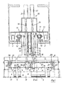
- Fig. 1 einen Teil-Querschnitt durch eine Filterpresse nach der Erfindung,
- Fig. 2 einen Schnitt gemäß der Linie II-II in Fig. 1 zur Erläuterung der in Schüttelposition befindlichen Schütteleinrichtung der Filterpresse und
- Fig. 3 eine Ansicht analog zur Fig. 2, wobei jedoch die Schütteleinrichtung in der Grundstellung gezeigt ist.
- An zwei über die Länge der Filterpresse sich erstreckenden I-Führungsschienen 1, 2, sind eine Vielzahl von Filterplatten 3 verfahrbar aufgehängt, von denen nur eine Filterplatte mit ihrem oberen Bereich in den Figuren gezeigt ist. Die Filterplatten 3 bestehen jeweils aus einer mit einer Ausnehmung, einem sogenannten Filterspiegel 4, versehenen Stützplatte 5, an deren ebener Seite eine Preßmembran 6 mittels eines Rahmens 7 festgespannt ist. An die seitlichen Enden der Filterplatte 3 ist oben ein insgesamt etwa U-förmiges Aufhängejoch 8 befestigt, an dem zwei nach oben ragende Aufhängearme 9, 10 angebracht sind, welche Laufrollen 11 tragen, die auf Sonderführungsprofilen 12 laufen, welche ihrerseits auf den unteren Innenschenkeln der I-Führungsschienen 1, 2 angebracht sind. Auf diesen unteren Innenschenkeln der Schienen 1, 2 ist ferner ein Plattentransport-Schlitten 13 verfahrbar gelagert, welcher eine steuerbare Plattenmitnehmereinrichtung 14 trägt, die mit einer auf und ab steuerbaren Mitnehmernase 15 an einem mittleren Jochstück 16 der jeweils zu transportierenden Filterplatte 3 angreift. Aufbau und Arbeitsweise einer solchen Plattenmitnahmeeinrichtung 14 sind beispielsweise in der DE-PS 29 23 864 beschrieben.
- Die Filterplatten 3 sind beidseits jeweils mit einem Filtertuch 17, 18 bespannt, wozu die Filtertücher oben mit Schlaufen versehen sind, in die jeweils eine Filtertuch-Stange 19, 20 eingeschoben ist. Diese Stangen 19, 20 sind endseitig über Schwenkhebel 21 bzw. 22 an einer mit Abstand sich oberhalb des oberen Randes der Filterplatte 3 erstreckenden Achse 23 lose gelagert, die ihrerseits in den Querschenkeln des U-förmigen Aufhängejoches 8 der Plattenaufhängung gelagert ist. Im mittleren Bereich sind auf dieser Achse 23 zwei Doppelhebel 24, 25 nebeneinander gelagert, die nach oben hin konvex gekrümmt sind und deren Hebelarmverhältnis etwa 1:2,5 beträgt. Die längeren Hebelarme 26, 27 der Doppelhebel tragen an ihren Enden die Filtertuch-Stangen 19, 20, wobei die beiden Doppelhebel 24, 25 symmetrisch zu der durch die Achse 23 verlaufende Vertikalmittelebene der Filterplatte angeordnet sind. Der längere Arm der Doppelhebel 24, 25 ist in der Grundstellung nahezu senkrecht gerichtet.
- Die seitlichen Schwenkhebel 21, 22 besitzen dieselbe Form wie die längeren Hebelarme 26, 27 der mittigen Doppelhebel 24, 25, weshalb sie in den Fig. 2 und 3 verdeckt sind. An jeder Filterplattenseite ist zwischen dem Paar von Schwenkhebeln 21, 22 jeweils eine Zugfeder 28 eingespannt, die in der Grundstellung gemäß Fig. 3 die Filtertuchstangen 19, 20 ein deutliches Stück weit einwärts über die oberen Ecken der Filterplatte 3 hinweg ziehen, so daß zumindest der Schlaufenbereich der Filtertücher einwärts abgebogen ist.
- Auf dem Transportschlitten 13 ist eine Schütteleinrichtung 30 angeordnet, welche zwei hydraulische oder pneumatische Verstellzylinder 31, 32 umfaßt, deren Kolbenstangen 33, 34 abwärts gerichtet sind und- unter Einfassung der Plattenmitnahmeeinrichtung 24 - durch Führungsrohre 35, 36 hindurch ragen und in der nicht ausgefahrenen Stellung bis zu den unteren Enden der Rohre 35, 36 etwa reichen und damit kurz oberhalb des Mitnahmejoches 16 liegen. Die Kolbenstangen 33, 34 sind jeweils auf die kurzen Arme 37, 38 der Doppelhebel 24, 25 gerichtet, wie in Fig. 3 strichpunktiert angedeutet ist. Bei einem Ausfahren der Kolbenstangen 33, 34 treffen diese auf die Hebelarme 37, 38 auf und verschwenken die Doppelhebel 24, 27 zusammen mit den Filtertuch-Stangen 19, 20 in die in Fig. 2 gezeigte Stellung, in der die Filtertücher 17, 18 in eine Schrägstellung weg von der Filterplatte 3 gezogen und wieder gespannt sind.
- Wie aus Fig. 1 ersichtlich ist, ist die Schütteleinrichtung 30 in dem ohnehin von den beiden I-Führungsschienen 1, 2 beanspruchten Raum untergebracht und baulich in die Plattentransporteinrichtung integriert.
- Beim gezeigten Ausführungsbeispiel folgen innerhalb des Filterplattenpaketes jeweils eine beidseits mit Filtertüchern 17, 18 überspannte Filterplatte 3 und eine im übrigen identische, aber nicht mit Filtertüchern überspannte Zwischenplatte 5, 6, 7 aufeinander.
Claims (7)
Applications Claiming Priority (2)
| Application Number | Priority Date | Filing Date | Title |
|---|---|---|---|
| DE3933740A DE3933740A1 (de) | 1989-10-10 | 1989-10-10 | Filterpresse |
| DE3933740 | 1989-10-10 |
Publications (2)
| Publication Number | Publication Date |
|---|---|
| EP0422521A1 true EP0422521A1 (de) | 1991-04-17 |
| EP0422521B1 EP0422521B1 (de) | 1994-06-08 |
Family
ID=6391148
Family Applications (1)
| Application Number | Title | Priority Date | Filing Date |
|---|---|---|---|
| EP90119153A Expired - Lifetime EP0422521B1 (de) | 1989-10-10 | 1990-10-05 | Filterpresse |
Country Status (3)
| Country | Link |
|---|---|
| US (1) | US5110467A (de) |
| EP (1) | EP0422521B1 (de) |
| DE (2) | DE3933740A1 (de) |
Cited By (1)
| Publication number | Priority date | Publication date | Assignee | Title |
|---|---|---|---|---|
| DE19945599A1 (de) * | 1999-09-23 | 2001-03-29 | Baker Hughes De Gmbh | Plattenfilterpresse mit automatischem Filterkuchenaustrag |
Families Citing this family (5)
| Publication number | Priority date | Publication date | Assignee | Title |
|---|---|---|---|---|
| DE4344300C1 (de) * | 1993-12-23 | 1994-10-13 | Netzsch Erich Holding | Filterplattenanordnung für Filterpressen |
| DE19850602C1 (de) * | 1998-11-03 | 2000-08-17 | Erich Netzsch Gmbh & Co Kg | Verfahren zum Entleeren von Filterpressen |
| DE10061918B4 (de) * | 2000-12-12 | 2006-04-27 | Richard Van Egdom | Filterpresse mit einer Kuchenabwurfeinrichtung |
| KR102519150B1 (ko) * | 2022-06-03 | 2023-04-06 | (주)동일캔바스엔지니어링 | 여과포 순환 필터프레스의 다기능대차 |
| CN116550022B (zh) * | 2023-02-28 | 2025-12-05 | 中铁十五局集团有限公司 | 一种压滤机泥饼自动脱落装置及其工作方法 |
Citations (3)
| Publication number | Priority date | Publication date | Assignee | Title |
|---|---|---|---|---|
| DE1813792A1 (de) * | 1968-11-05 | 1970-05-27 | Kurita Ken I | Vorrichtung zum Herausloesen des Filterkuchens in Filterpressen |
| EP0225972A1 (de) * | 1985-11-19 | 1987-06-24 | Sumitomo Chemical Company, Limited | Vibrationsanlage für ein Filtertuch einer Filterpresse |
| DE3842867A1 (de) * | 1987-12-26 | 1989-07-06 | Ishigaki Mech Ind | Vorrichtung zum entfernen von filterkuchen aus einer filterpresse |
Family Cites Families (5)
| Publication number | Priority date | Publication date | Assignee | Title |
|---|---|---|---|---|
| JPS5285769A (en) * | 1976-01-07 | 1977-07-16 | Noritake Iron Works | Method of locating dregs remover in filter presses |
| DE2923864A1 (de) * | 1979-06-13 | 1980-12-18 | Rittershaus & Blecher Gmbh | Vorrichtungen fuer filterpressen zum verschieben der jeweils vordersten filterplatte |
| US4558641A (en) * | 1983-12-07 | 1985-12-17 | Kurita Machinery Manufacturing Company Limited | Apparatus for oscillating filter cloth of filter press |
| DE3608774A1 (de) * | 1986-03-15 | 1987-09-17 | Rittershaus & Blecher Gmbh | Filterpresse |
| JPH01207105A (ja) * | 1988-02-15 | 1989-08-21 | Ishigaki Kiko Kk | フイルタプレスにおける濾板の振動装置 |
-
1989
- 1989-10-10 DE DE3933740A patent/DE3933740A1/de not_active Withdrawn
-
1990
- 1990-10-05 US US07/593,807 patent/US5110467A/en not_active Expired - Lifetime
- 1990-10-05 DE DE59006022T patent/DE59006022D1/de not_active Expired - Lifetime
- 1990-10-05 EP EP90119153A patent/EP0422521B1/de not_active Expired - Lifetime
Patent Citations (3)
| Publication number | Priority date | Publication date | Assignee | Title |
|---|---|---|---|---|
| DE1813792A1 (de) * | 1968-11-05 | 1970-05-27 | Kurita Ken I | Vorrichtung zum Herausloesen des Filterkuchens in Filterpressen |
| EP0225972A1 (de) * | 1985-11-19 | 1987-06-24 | Sumitomo Chemical Company, Limited | Vibrationsanlage für ein Filtertuch einer Filterpresse |
| DE3842867A1 (de) * | 1987-12-26 | 1989-07-06 | Ishigaki Mech Ind | Vorrichtung zum entfernen von filterkuchen aus einer filterpresse |
Cited By (1)
| Publication number | Priority date | Publication date | Assignee | Title |
|---|---|---|---|---|
| DE19945599A1 (de) * | 1999-09-23 | 2001-03-29 | Baker Hughes De Gmbh | Plattenfilterpresse mit automatischem Filterkuchenaustrag |
Also Published As
| Publication number | Publication date |
|---|---|
| DE59006022D1 (de) | 1994-07-14 |
| EP0422521B1 (de) | 1994-06-08 |
| DE3933740A1 (de) | 1991-04-11 |
| US5110467A (en) | 1992-05-05 |
Similar Documents
| Publication | Publication Date | Title |
|---|---|---|
| DE3626131C2 (de) | Abstreifvorrichtung für den Rücklaufbereich von Förderbändern | |
| DE3617872C2 (de) | Vorrichtung zum Flüssigkeitsentzug aus Suspensionen | |
| DE1816165A1 (de) | Fahrbare Siebanlage | |
| DE3000217C2 (de) | Vorrichtung zum Überführen von abgelängten Drähten aus einem losen Drahtbündel in eine Einfachlage von parallelen Drähten | |
| DE2851117A1 (de) | Sammel- und ablegevorrichtung fuer pressballen | |
| DE3842867A1 (de) | Vorrichtung zum entfernen von filterkuchen aus einer filterpresse | |
| EP0422521B1 (de) | Filterpresse | |
| DE3126715C2 (de) | ||
| DE29510199U1 (de) | Luftfedervorrichtung für Fahrzeugachsen | |
| DE2425083B2 (de) | Filtervorrichtung mit einem oder mehreren Filtersäcken | |
| DE69507317T2 (de) | Förder-bandtragvorrichtung mit abgabestation und selbstentladendes schiff mit einer solchen vorrichtung | |
| DE69405904T2 (de) | Lade- und Kippmaschine zum Abnehmen von Glasscheiben nacheinander von einem Stapel | |
| DE69514210T2 (de) | Vorrichtung und Verfahren zum Freimachen eines Siebs einer flachen Siebdruckmaschine | |
| DE19707070C2 (de) | Filterpresse | |
| DE4001740A1 (de) | Vorrichtung zum ausbreiten von ware | |
| DD151252A5 (de) | Schuettlerloser selbstfahrender maehdrescher | |
| DE3336937C2 (de) | Vorrichtung zum Abnehmen einzelner scheibenförmiger Gegenstände, insbesondere Glasscheiben, von einem Scheibenvorrat | |
| CH85340A (de) | Apparat zum Einsammeln von am Boden liegendem Obst. | |
| WO1992018676A1 (de) | Klemmvorrichtung für eine flächige fadenschicht und verwendung derselben | |
| DE4109408C2 (de) | Aufnahme- und Transportvorrichtung für die Kettfadenwächter-Einheit in Webmaschinen | |
| DE4344300C1 (de) | Filterplattenanordnung für Filterpressen | |
| DE4019545A1 (de) | Schlammentwaesserungsvorrichtung | |
| DE4009699C2 (de) | Verfahren und Anordnung zum Stützen des Körpers einer Papiermaschine oder dergleichen | |
| DE417297C (de) | Schuettelnder Planknotenfaenger fuer die Papier- und Celluloseherstellung mit auf-gehaengtem Knotenauslauf, der eine hin und her gehende Bewegung ausfuehrt | |
| WO2002047788A1 (de) | Filterpresse mit einer kuchenabwurfeinrichtung |
Legal Events
| Date | Code | Title | Description |
|---|---|---|---|
| PUAI | Public reference made under article 153(3) epc to a published international application that has entered the european phase |
Free format text: ORIGINAL CODE: 0009012 |
|
| AK | Designated contracting states |
Kind code of ref document: A1 Designated state(s): BE CH DE FR GB IT LI NL SE |
|
| 17P | Request for examination filed |
Effective date: 19910704 |
|
| 17Q | First examination report despatched |
Effective date: 19930223 |
|
| GRAA | (expected) grant |
Free format text: ORIGINAL CODE: 0009210 |
|
| AK | Designated contracting states |
Kind code of ref document: B1 Designated state(s): BE CH DE FR GB IT LI NL SE |
|
| REF | Corresponds to: |
Ref document number: 59006022 Country of ref document: DE Date of ref document: 19940714 |
|
| ITF | It: translation for a ep patent filed | ||
| GBT | Gb: translation of ep patent filed (gb section 77(6)(a)/1977) |
Effective date: 19940912 |
|
| ET | Fr: translation filed | ||
| EAL | Se: european patent in force in sweden |
Ref document number: 90119153.6 |
|
| PLBE | No opposition filed within time limit |
Free format text: ORIGINAL CODE: 0009261 |
|
| STAA | Information on the status of an ep patent application or granted ep patent |
Free format text: STATUS: NO OPPOSITION FILED WITHIN TIME LIMIT |
|
| 26N | No opposition filed | ||
| NLS | Nl: assignments of ep-patents |
Owner name: BAKER HUGHES (DEUTSCHLAND) GMBH |
|
| REG | Reference to a national code |
Ref country code: CH Ref legal event code: PUE Owner name: RITTERSHAUS & BLECHER GMBH TRANSFER- BAKER HUGHES |
|
| REG | Reference to a national code |
Ref country code: FR Ref legal event code: TP |
|
| REG | Reference to a national code |
Ref country code: GB Ref legal event code: IF02 |
|
| PGFP | Annual fee paid to national office [announced via postgrant information from national office to epo] |
Ref country code: NL Payment date: 20030919 Year of fee payment: 14 |
|
| PGFP | Annual fee paid to national office [announced via postgrant information from national office to epo] |
Ref country code: GB Payment date: 20031001 Year of fee payment: 14 |
|
| PGFP | Annual fee paid to national office [announced via postgrant information from national office to epo] |
Ref country code: FR Payment date: 20031020 Year of fee payment: 14 |
|
| PGFP | Annual fee paid to national office [announced via postgrant information from national office to epo] |
Ref country code: SE Payment date: 20031021 Year of fee payment: 14 |
|
| PGFP | Annual fee paid to national office [announced via postgrant information from national office to epo] |
Ref country code: CH Payment date: 20031022 Year of fee payment: 14 |
|
| PGFP | Annual fee paid to national office [announced via postgrant information from national office to epo] |
Ref country code: BE Payment date: 20031125 Year of fee payment: 14 |
|
| PG25 | Lapsed in a contracting state [announced via postgrant information from national office to epo] |
Ref country code: GB Free format text: LAPSE BECAUSE OF NON-PAYMENT OF DUE FEES Effective date: 20041005 |
|
| PG25 | Lapsed in a contracting state [announced via postgrant information from national office to epo] |
Ref country code: SE Free format text: LAPSE BECAUSE OF NON-PAYMENT OF DUE FEES Effective date: 20041006 |
|
| PG25 | Lapsed in a contracting state [announced via postgrant information from national office to epo] |
Ref country code: LI Free format text: LAPSE BECAUSE OF NON-PAYMENT OF DUE FEES Effective date: 20041031 Ref country code: CH Free format text: LAPSE BECAUSE OF NON-PAYMENT OF DUE FEES Effective date: 20041031 Ref country code: BE Free format text: LAPSE BECAUSE OF NON-PAYMENT OF DUE FEES Effective date: 20041031 |
|
| BERE | Be: lapsed |
Owner name: *BAKER HUGHES (DEUTSCHLAND) G.M.B.H. Effective date: 20041031 |
|
| PG25 | Lapsed in a contracting state [announced via postgrant information from national office to epo] |
Ref country code: NL Free format text: LAPSE BECAUSE OF NON-PAYMENT OF DUE FEES Effective date: 20050501 |
|
| GBPC | Gb: european patent ceased through non-payment of renewal fee |
Effective date: 20041005 |
|
| EUG | Se: european patent has lapsed | ||
| REG | Reference to a national code |
Ref country code: CH Ref legal event code: PL |
|
| PG25 | Lapsed in a contracting state [announced via postgrant information from national office to epo] |
Ref country code: FR Free format text: LAPSE BECAUSE OF NON-PAYMENT OF DUE FEES Effective date: 20050630 |
|
| NLV4 | Nl: lapsed or anulled due to non-payment of the annual fee |
Effective date: 20050501 |
|
| REG | Reference to a national code |
Ref country code: FR Ref legal event code: ST |
|
| PG25 | Lapsed in a contracting state [announced via postgrant information from national office to epo] |
Ref country code: IT Free format text: LAPSE BECAUSE OF NON-PAYMENT OF DUE FEES;WARNING: LAPSES OF ITALIAN PATENTS WITH EFFECTIVE DATE BEFORE 2007 MAY HAVE OCCURRED AT ANY TIME BEFORE 2007. THE CORRECT EFFECTIVE DATE MAY BE DIFFERENT FROM THE ONE RECORDED. Effective date: 20051005 |
|
| BERE | Be: lapsed |
Owner name: *BAKER HUGHES (DEUTSCHLAND) G.M.B.H. Effective date: 20041031 |
|
| PGFP | Annual fee paid to national office [announced via postgrant information from national office to epo] |
Ref country code: DE Payment date: 20091026 Year of fee payment: 20 |
|
| PG25 | Lapsed in a contracting state [announced via postgrant information from national office to epo] |
Ref country code: DE Free format text: LAPSE BECAUSE OF EXPIRATION OF PROTECTION Effective date: 20101005 |