EP0422564A2 - Kochfeld mit gasbeheizten Brennstellen - Google Patents
Kochfeld mit gasbeheizten Brennstellen Download PDFInfo
- Publication number
- EP0422564A2 EP0422564A2 EP19900119269 EP90119269A EP0422564A2 EP 0422564 A2 EP0422564 A2 EP 0422564A2 EP 19900119269 EP19900119269 EP 19900119269 EP 90119269 A EP90119269 A EP 90119269A EP 0422564 A2 EP0422564 A2 EP 0422564A2
- Authority
- EP
- European Patent Office
- Prior art keywords
- gas
- hob
- plate
- gas burner
- burners
- Prior art date
- Legal status (The legal status is an assumption and is not a legal conclusion. Google has not performed a legal analysis and makes no representation as to the accuracy of the status listed.)
- Granted
Links
- 230000007246 mechanism Effects 0.000 claims abstract description 15
- 239000002241 glass-ceramic Substances 0.000 claims description 5
- 239000000463 material Substances 0.000 claims description 5
- 239000000919 ceramic Substances 0.000 abstract 1
- 238000010411 cooking Methods 0.000 description 3
- 230000003670 easy-to-clean Effects 0.000 description 2
- 239000011324 bead Substances 0.000 description 1
- 238000004140 cleaning Methods 0.000 description 1
- 238000010438 heat treatment Methods 0.000 description 1
- 210000000056 organ Anatomy 0.000 description 1
- 230000001105 regulatory effect Effects 0.000 description 1
Images

Classifications
-
- F—MECHANICAL ENGINEERING; LIGHTING; HEATING; WEAPONS; BLASTING
- F24—HEATING; RANGES; VENTILATING
- F24C—DOMESTIC STOVES OR RANGES ; DETAILS OF DOMESTIC STOVES OR RANGES, OF GENERAL APPLICATION
- F24C3/00—Stoves or ranges for gaseous fuels
- F24C3/08—Arrangement or mounting of burners
- F24C3/085—Arrangement or mounting of burners on ranges
Definitions
- the invention relates to a hob with gas-heated burners, the hob being covered by a flat hob plate made of glass ceramic or comparable material, under which the gas burners are arranged.
- the gas burners are usually arranged in a recessed manner in a hob, the cooking material support, which is usually crown-shaped, being arranged in a ring around the gas burner.
- the cooking material support which is usually crown-shaped, being arranged in a ring around the gas burner.
- gas burners are often arranged in the hob.
- the cookware supports of the various gas burners are usually on one level of the domestic gas range.
- gas burners are located lower in the gas burner trough, cleaning the gas burner trough is made more difficult. It is also not possible, for example, to cover the gas burners with a common plate, as in an electric cooker.
- each gas burner has a lifting mechanism, the latter being operable by a handle on the operating bar of the gas range. The gas burner can only be ignited in its operating position.
- the hob plate and the cover plates or cover plates assigned to the gas burners are glass ceramic plates.
- the gas burner can be connected to a flexible gas feed line.
- Known elements can serve as the lifting mechanism, although cam disks are particularly recommended. These cams can be actuated in many ways with known elements, such as flexible shafts or cardan shafts.
- a separate gas burner trough is arranged under each gas burner of the gas range. When the gas burner is raised to the operating level, the lifting mechanisms engage under the hob recessed plate and lift it up with the burner and hob support and plate.
- a gas burner 2 in a hob 1 there is a gas burner 2 in a hob 1; it is attached to a gas burner trough 3.
- This gas burner trough also carries the hotplate support 4.
- the end face or cooking surface of the gas range is covered by a hob plate 5; it has cutouts 6, which can be closed into the cutouts 5 by a hotplate support plate 7. If the gas burner 2 is put into operation, the gas burner trough 3 with the gas burner 2 and the hotplate support 4 together with the hotplate cover plate 7 is raised into the dot-dash position. The gas burner 2 can now be ignited.
- the hob 5 provided with cutouts thus remains below and outside the burning area of the gas burner and can hardly warm up.
- the hotplate cover plate 7 has a secure hold, it is surrounded by a ring bead 8 on one side.
- Lifting mechanisms of various types can be used to lift the gas burner. It is recommended, for example, to use cams 9 and 9 '.
- the latter cams are, as indicated, moved in the opposite direction, such that the gas burner trough 3 can be raised and lowered vertically in the direction of arrow 10.
- the latter cams are rotatably supported in bearing supports 11 and are held by the supports; they are moved by control shafts 12; they are connected to handles via universal joints.
- the gas burner trough 3 is secured by lateral guides 13 in such a way that vertical movement is possible, but horizontal movement is excluded.
- a gas burner nozzle 14 supplies gas and air to the gas burner 2.
- the latter gas burner nozzle is connected to the gas supply pipe 15.
- the supply of gas and air to the gas burner 2 can only take place when the gas burner is raised in its operating position.
- the control shafts 12 carry toothed segments 16 here, such that when the control shafts rotate, the cam plates 9 and 9 pivot in the opposite direction of rotation and raise the gas burner recess 3 with the gas burner hotplate and plate 7.
- Cardan joints 17 are connected to the steep shafts or control rods.
- cams 9 and 9 can also be designed in a different way.
- cam disks instead of the cam disks, circular eccentric disks or segments can occur, and there is also the possibility of designing the lifting mechanism in the form of rods.
- Fig. 3 is shown schematically that instead of the gimbal 12 also a flexible shaft 12 'can occur, which is rotated by the eccentric 9, such that the gas burner trough 3 can be raised and lowered with the burner 2.
- the cam 9 In the end positions of the cam 9 there are notches 10 or detent depressions 18 ', which are intended to ensure that only a rest position of the gas burner is ensured in these end positions.
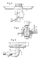
- the handle 20 for adjusting the lifting mechanism is attached to the dashboard 19.
- the handle 20 is annular, whereby on the ring connector 20 'a toothed ring 21 is placed, which is in engagement with a pinion 22. It serves to drive the control shaft 12 or 12 'of the lifting mechanism.
- a push button 23 is guided, but which is locked by a nose 24 of the ring socket 20 'of the toothed ring 21.
- the push button 23 now being able to be actuated so that the push button tappet 26 opens the gas valve 27 for the gas burner.
- the gas burner is in the raised operating position.
- the gas supply to the gas burner 2 can now be regulated by means of the rotary knob 30.
- the push button 23 is pressed again, it jumps back to the starting position shown.
- the gas supply to the gas burner is cut off; knob 30 is now also out of operation.
- FIG. 5 Another embodiment of the gas supply is shown in FIG. 5.
- the gas burner trough 3 with the gas burner 2, not shown, with the gas supply connection 28 is raised by the lifting mechanism, not shown, the gas supply being effected via a flexible gas feed line 29; it can be formed in the manner of a hose connector.
Landscapes
- Engineering & Computer Science (AREA)
- Chemical & Material Sciences (AREA)
- Combustion & Propulsion (AREA)
- Mechanical Engineering (AREA)
- General Engineering & Computer Science (AREA)
- Baking, Grill, Roasting (AREA)
- Combinations Of Kitchen Furniture (AREA)
- Gas Burners (AREA)
- Cookers (AREA)
Abstract
Description
- Die Erfindung bezieht sich auf ein Kochfeld mit gasbeheizten Brennstellen, wobei das Kochfeld durch eine ebene Kochfeldplatte aus Glaskeramik oder vergleichbarem Material abgedeckt ist, unter der die Gasbrenner angeordnet sind.
- Bei Haushalt-Gasherden sind die Gasbrenner meist vertieft in einer Kochstellenmulde angeordnet, wobei die meist kronenförmig ausgebildete Kochgutauflage ringförmig um den Gasbrenner angeordnet ist. In der Kochstellenmulde sind vielfach mehrere Gasbrenner angeordnet. Die Kochgutauflagen der verschiedenen Gasbrenner liegen meist in einer Ebene des Haushalt-Gasherdes.
- Es ist auch bekannt, Kochfelder mit gasbeheizten Brennstellen mit einer durchgehenden Kochfläche aus Glaskeramik oder vergleichbarem Material auszustatten, so daß eine ebene, durchgehende Arbeitsfläche gebildet wird. Aus heiztechnischen Gründen sind derartige Kochfelder problematisch.
- Bedingt dadurch, daß Gasbrenner tiefer in der Gasbrennermulde gelegen sind, ist ein Reinigen der Gasbrennermulde erschwert. Es ist auch nicht möglich, beispielsweise wie bei einem Elektrokochherd die Gasbrenner mit einer gemeinsamen Platte abzudecken.
- Es ist Aufgabe der Erfindung die Gasbrenner so auszurüsten, daß die Gasbrenner einerseits leicht zu reinigen sind, andererseits aber auch den Gasherd so zu gestalten, daß die Gasbrenner bei Nichtbenutzung durch eine Platte abdeckbar sind, auf der die Kochgeschirre hin- und hergeschoben werden können.
- Dies geschieht gemäß der Erfindung dadurch, daß die ebene Kochfeldplatte oberhalb der Gasbrenner ausgespart ist, daß die Gasbrenner ihrerseits durch in ihrer Ruhestellung die Aussparungen der Kochfeldplatte ausfüllenden Abdeckplatten bzw. Abdeckscheiben abgedeckt sind und daß ein Verstellmechanismus für die Gasbrenner zum bedarfsweisen Anheben der Gasbrenner zusammen mit ihrer Abdeckplatte oder Abdeckscheibe aus der Ruhestellung in eine Arbeitsstellung angeordnet ist. Zu diesem Zweck besitzt jeder Gasbrenner einen Hubmechanismus, wobei letzterer von einer Handhabe an der Bedienungsleiste des Gasherdes betätigbar ist. Der Gasbrenner ist nur in seiner Betriebsstellung zündbar.
- Vorteilhaft ist es, wenn die Kochfeldplatte sowie die den Gasbrennern zugeordneten Abdeckplatten bzw. Abdeckscheiben Glaskeramikplatten sind. Beim Anheben des Gasbrenners mit der Kochstellenauflage und Platte ist der Brenner leicht zündbar und auch, sofern erforderlich, leicht zu reinigen. Der Gasbrenner kann dabei mit einer flexiblen Gaszuleitung verbunden sein. Als Hubmechanismus können bekannte Elemente dienen, wobei jedoch sich Kurvenscheiben besonders empfehlen. Diese Kurvenscheiben können mannigfach mit bekannten Elementen, wie biegsamen Wellen oder Kardanwellen betätigt werden. Vorteilhaft ist es, wenn unter jedem Gasbrenner des Gasherdes eine eigene Gasbrennermulde angeordnet ist. Beim Anheben des Gasbrenners in die Betriebsebene greifen die Hubmechanismen unter die Kochstellen-Muldenscheibe und heben diese mit Brenner und Kochstellenauflage nebst Platte an.
- Es ist zweckmäßig, unter der Gasbrennermulde für jeden Gasbrenner mehrere Kurvenscheiben anzuordnen und diese Kurvenscheiben gegensinnig zu betreiben. Damit wird vermieden, daß durch die Kurvenscheiben die für jeden Brenner vorgesehene Gasbrennermulde seitlich verschoben wird. Trotzdem ist es erforderlich, für jeden Gasbrenner und Gasbrennermulde senkrechte Führungen vorzusehen sowie die Kurvenscheiben derart auszubilden, daß sie nur entweder in die Betriebsebene des Gasbrenners oder in seine Ruhestellung schwenkbar sind. Es empfiehlt sich daher, die Drehachsen der Kurvenscheiben mit Zahnsegmenten zu versehen, die ineinander reifen derart, daß beim Stellen einer Kurvenscheibe die andere Kurvenscheibe mitbetätigt wird, jedoch in einem entgegengesetzten Drehsinne schwenkt.
- Ein nach der Erfindung gestalteter Gasbrenner für einen Gasherd ist in den Zeichnungen dargestellt, wobei jedoch darauf aufmerksam gemacht wird, daß manche Elemente durch andere bekannte Organe ersetzt werden können. Es bedeuten:
- Fig. 1 einen lotrechten Schnitt durch einen Gasbrenner
- Fig. 2 eine Draufsicht auf den Gasbrenner gemäß Fig. 1 gemäß der Schnittlinie II-II,
- Fig. 3 eine andere Anordnung des Hubmechanismus,
- Fig. 4 eine Betätigungshandhabe zur Betätigung des Gasbrenners und
- Fig. 5 die Gaszuleitung zu einem Gasbrenner
- In einem Koch-Gasherd (nicht dargestellt) befindet sich in einer Kochmulde 1 ein Gasbrenner 2; er ist an einer Gasbrennermulde 3 befestigt. Diese Gasbrennermulde trägt auch die Kochstellenauflage 4. Die Stirnfläche oder auch Kochfläche des Gasherdes ist durch eine Kochfeldplatte 5 abgedeckt; sie besitzt Ausschnitte 6, die von einer Kochstellen-Auflageplatte 7 in die Ausschnitte 5 schließbar sind. Wird der Gasbrenner 2 in Betrieb genommen, so wird die Gasbrennermulde 3 mit dem Gasbrenner 2 und der Kochstellenauflage 4 mitsamt der Kochstellenabdeckplatte 7 in die strichpunktierte Stellung angehoben. Der Gasbrenner 2 kann jetzt gezündet werden. Die mit Ausschnitten versehene Kochfeldplatte 5 bleibt somit unterhalb und außerhalb des Brennbereiches des Gasbrenners und kann sich kaum erwärmen. Damit die Kochstellenabdeckplatte 7 einen sicheren Halt aufweist, ist sie mit einem einseitigen Ringwulst 8 umgeben. Zum Anheben des Gasbrenners können Hubmechanismen der verschiedensten Art dienen. Empfehlenswert ist es beispielsweise, Kurvenscheiben 9 und 9′ zu verwenden. Letztere Kurvenscheiben werden, wie angedeutet, im entgegengesetzten Drehsinn bewegt, derart, daß die Gasbrennermulde 3 in Pfeilrichtung 10 vertikal angehoben und gesenkt werden kann. Letztere Kurvenscheiben sind in Lagerstützen 11 drehbar gelagert und werden von den Stützen gehalten; sie werden von Stellwellen 12 bewegt; sie stehen über Kardangelenke mit Handhaben in Verbindung. Die Gasbrennermulde 3 ist durch seitliche Führungen 13 gesichert, der- art, daß eine vertikale Bewegung möglich, hingegen eine horizontale Bewegung ausgeschlossen ist. Eine Gasbrennerdüse 14 liefert Gas und Luft zum Gasbrenner 2. Letztere Gasbrennerdüse steht in Verbindung mit dem Gaszuleitungsrohr 15. Die Zuleitung von Gas und Luft zum Gasbrenner 2 kann nur erfolgen, wenn der Gasbrenner in seiner Betriebsstellung angehoben ist. Die Stellwellen 12 tragen hier Zahnsegmente 16, derart, daß bei einer Drehung der Stellwellen die Kurvenscheibe 9 und 9, in entgegengesetzter Drehrichtung schwenken und die Gasbrennermulde 3 mit Gasbrenner-Kochstellenauflage und Platte 7 anheben. Kardangelenke 17 sind mit den Steilwellen bzw. Stellgestängen verbunden.
- Es versteht sich, daß der hier aus Kurvenscheiben 9 und 9, dargestellte Hubmechanismus auch in anderer Weise ausgebildet sein kann. So können beispielsweise anstelle der Kurvenscheiben kreisförmige Exzenterscheiben bzw. Segmente treten, auch besteht die Möglichkeit, den Hubmechanismus in Form von Gestängen auszubilden.
- In Fig. 3 ist schematisch dargestellt, daß anstelle der Kardangestänge 12 auch eine biegsame Welle 12′ treten kann, welche durch die Exzenterscheibe 9 gedreht wird, derart, daß die Gasbrennermulde 3 mit dem Brenner 2 gehoben und gesenkt werden kann. In den Endstellungen der Kurvenscheibe 9 befinden sich Rasten 10 bzw. Rastmulden 18′, welche sicherstellen sollen, daß in diesen Endstellungen nur eine Ruhestellung des Gasbrenners gewährleistet ist.
- An der Armaturenleiste 19 ist, wie Fig. 4 zeigt, die Handhabe 20 zum Verstellen des Hubmechanismus angebracht. Die Handhabe 20 ist ringförmig gebildet, wobei auf den Ringstutzen 20′ ein Zahnring 21 aufgesetzt ist, welcher im Eingriff mit einem Zahnritzel 22 steht. Es dient zum Antrieb der Stellwelle 12 bzw. 12′ des Hubmachanismus. Durch den Zahnring 20 ist ein Druckknopf 23 geführt, der jedoch von einer Nase 24 des Ringstutzens 20′ des Zahnringes 21 gesperrt ist. Solange nämlich ist die Handhabe 20 gedreht, daß die Nase 24 vor eine im Druckknopf 23 eingelassene Nut 25 gestellt ist, wobei nunmehr der Druckknopf 23 betätigt werden kann, so daß der Druckknopfstößel 26 das Gasventil 27 für den Gasbrenner öffnet. Ist die Nase 24 der Handhabe 20 vor die Nut 25 gestellt, so befindet sich der Gasbrenner in der angehobenen Betriebslage. Die Gaszufuhr zum Gasbrenner 2 kann nunmehr mittels des Drehknopfes 30 geregelt werden. Beim nochmaligen Drücken, des Druckknopfes 23 springt dieser in die dargestellte Ausgangslage zurück Dabei wird die Gaszufuhr zum Gasbrenner unterbunden; auch der Drehknopf 30 ist jetzt außer Betrieb.
- Eine andere Ausbildungform der Gaszuführung ist in Fig. 5 dargestellt. Hier wird die Gasbrennermulde 3 mit dem nicht weiter dargestellten Gasbrenner 2 mit dem Gaszuführungsstutzen 28 vom nicht weiter dargestellten Hubmechanismus angehoben, wobei hier die Gaszuführung über eine flexible Gaszuleitung 29 erfolgt; sie kann in der Art eines Schlauchstutzens gebildet sein.
Claims (10)
Priority Applications (1)
| Application Number | Priority Date | Filing Date | Title |
|---|---|---|---|
| AT90119269T ATE101432T1 (de) | 1989-10-10 | 1990-10-08 | Kochfeld mit gasbeheizten brennstellen. |
Applications Claiming Priority (2)
| Application Number | Priority Date | Filing Date | Title |
|---|---|---|---|
| DE3933833A DE3933833A1 (de) | 1989-10-10 | 1989-10-10 | Kochfeld mit gasbeheizten brennstellen |
| DE3933833 | 1989-10-10 |
Publications (3)
| Publication Number | Publication Date |
|---|---|
| EP0422564A2 true EP0422564A2 (de) | 1991-04-17 |
| EP0422564A3 EP0422564A3 (en) | 1991-11-21 |
| EP0422564B1 EP0422564B1 (de) | 1994-02-09 |
Family
ID=6391209
Family Applications (1)
| Application Number | Title | Priority Date | Filing Date |
|---|---|---|---|
| EP90119269A Expired - Lifetime EP0422564B1 (de) | 1989-10-10 | 1990-10-08 | Kochfeld mit gasbeheizten Brennstellen |
Country Status (4)
| Country | Link |
|---|---|
| EP (1) | EP0422564B1 (de) |
| AT (1) | ATE101432T1 (de) |
| DE (2) | DE3933833A1 (de) |
| ES (1) | ES2048922T3 (de) |
Cited By (5)
| Publication number | Priority date | Publication date | Assignee | Title |
|---|---|---|---|---|
| FR2701542A1 (fr) * | 1993-02-10 | 1994-08-19 | Soremam | Procédé et dispositif permettant de rendre, avec sécurité, un brûleur à gaz autoporteur escamotable par rapport à un plan de cuisson. |
| US5425354A (en) * | 1993-12-23 | 1995-06-20 | Tong Yang Magic Corp. | Portable gas range with folding tripod |
| EP0717242A1 (de) * | 1994-12-13 | 1996-06-19 | Whirlpool Europe B.V. | Verfahren und Vorrichtung zur leichten Bewegung eines Kochmuldengasbrenners |
| DE29715697U1 (de) * | 1997-09-02 | 1997-11-20 | Dessauer Geräteindustrie GmbH, 06847 Dessau | Gaskochstelle mit mehreren Brennerstellen |
| EP1779041A4 (de) * | 2004-07-13 | 2016-04-27 | Fisher & Paykel Appliances Ltd | Kochgerät |
Families Citing this family (1)
| Publication number | Priority date | Publication date | Assignee | Title |
|---|---|---|---|---|
| US5301113A (en) * | 1993-01-07 | 1994-04-05 | Ford Motor Company | Electronic system and method for calculating distance to empty for motorized vehicles |
Family Cites Families (3)
| Publication number | Priority date | Publication date | Assignee | Title |
|---|---|---|---|---|
| GB867237A (en) * | 1957-12-17 | 1961-05-03 | Oatley Technical Dev | Kitchen equipment unit including a cooker hotplate |
| US3830216A (en) * | 1971-03-15 | 1974-08-20 | Owens Illinois Inc | Countertop heating apparatus |
| DE3703466A1 (de) * | 1987-02-05 | 1988-08-18 | Buderus Ag | Kochfeld, bestehend aus mehreren, unterhalb einer durchgehenden kochflaeche aus glaskeramik angeordneten gasbeheizten brennstellen |
-
1989
- 1989-10-10 DE DE3933833A patent/DE3933833A1/de not_active Withdrawn
-
1990
- 1990-10-08 AT AT90119269T patent/ATE101432T1/de not_active IP Right Cessation
- 1990-10-08 EP EP90119269A patent/EP0422564B1/de not_active Expired - Lifetime
- 1990-10-08 ES ES90119269T patent/ES2048922T3/es not_active Expired - Lifetime
- 1990-10-08 DE DE90119269T patent/DE59004548D1/de not_active Expired - Fee Related
Cited By (6)
| Publication number | Priority date | Publication date | Assignee | Title |
|---|---|---|---|---|
| FR2701542A1 (fr) * | 1993-02-10 | 1994-08-19 | Soremam | Procédé et dispositif permettant de rendre, avec sécurité, un brûleur à gaz autoporteur escamotable par rapport à un plan de cuisson. |
| US5425354A (en) * | 1993-12-23 | 1995-06-20 | Tong Yang Magic Corp. | Portable gas range with folding tripod |
| EP0717242A1 (de) * | 1994-12-13 | 1996-06-19 | Whirlpool Europe B.V. | Verfahren und Vorrichtung zur leichten Bewegung eines Kochmuldengasbrenners |
| US6058927A (en) * | 1994-12-13 | 2000-05-09 | Whirlpool Europe B.V. | Method and device for achieving easy movement of a cooking hob gas burner |
| DE29715697U1 (de) * | 1997-09-02 | 1997-11-20 | Dessauer Geräteindustrie GmbH, 06847 Dessau | Gaskochstelle mit mehreren Brennerstellen |
| EP1779041A4 (de) * | 2004-07-13 | 2016-04-27 | Fisher & Paykel Appliances Ltd | Kochgerät |
Also Published As
| Publication number | Publication date |
|---|---|
| EP0422564B1 (de) | 1994-02-09 |
| EP0422564A3 (en) | 1991-11-21 |
| ATE101432T1 (de) | 1994-02-15 |
| DE59004548D1 (de) | 1994-03-24 |
| DE3933833A1 (de) | 1991-04-18 |
| ES2048922T3 (es) | 1994-04-01 |
Similar Documents
| Publication | Publication Date | Title |
|---|---|---|
| EP0729292B1 (de) | Herdmulde | |
| EP0962707A2 (de) | Bedieneinheit für ein elektrisches Haushaltgerät | |
| EP2215407B1 (de) | Bedienvorrichtung für ein hausgerät | |
| EP0422564B1 (de) | Kochfeld mit gasbeheizten Brennstellen | |
| DE1679204B1 (de) | Gaskochherd mit flammenlosen strahlungsbrennern | |
| EP1556651B1 (de) | Betätigungsvorrichtung für eine kochmulde | |
| EP2455669B1 (de) | Bedienvorrichtung für ein hausgerät mit einer muldenförmigen aufnahme sowie hausgerät, insbesondere kochfeld, mit einer derartigen bedienvorrichtung | |
| DE8915959U1 (de) | Kochfeld mit gasbeheizten Brennstellen | |
| EP1673579B1 (de) | Gaskochfeld | |
| DE3049491C2 (de) | Kochherd mit einer eine geschlossene Oberfläche aufweisenden wärmeübertragenden Platte | |
| DE9409951U1 (de) | Vorrichtung als Schaltuhr zur Steuerung und/oder Sicherung eines elektrischen Gerätes, wie z.B. eines Herdes o.dgl. | |
| DE102010044146A1 (de) | Bedienvorrichtung für ein Hausgerät mit einer muldenförmigen Aufnahme sowie Hausgerät, insbesondere Kochfeld, mit einer derartigen Bedienvorrichtung | |
| DE102009028191A1 (de) | Kochfeld und Gasherd | |
| WO2001073350A1 (de) | Kochgerät | |
| DE19505801C2 (de) | Herdmulde mit einem Kochfeld, dem ein Auflageelement zum Auflegen von Grill- oder Bratgut zugeordnet ist | |
| DE69104627T2 (de) | Einziehbarer kochbrenner für elektroherd mit abnehmbarer kochplatte. | |
| DE1266471B (de) | Mit festen oder fluessigen Brennstoffen befeuerter Herd mit einer mit elektrischen Kochplatten ausgestatteten Aufsatzherdplatte | |
| DE102010044145A1 (de) | Bedienvorrichtung für ein Hausgerät mit einer muldenförmigen Aufnahme sowie Hausgerät, insbesondere Kochfeld, mit einer derartigen Bedienvorrichtung | |
| EP0822377A2 (de) | Kochfeld für einen Elektro- oder Gasherd | |
| EP2455670B1 (de) | Bedienvorrichtung für ein hausgerät mit einer muldenförmigen aufnahme sowie hausgerät, insbesondere kochfeld, mit einer derartigen bedienvorrichtung | |
| DE654607C (de) | Gasherd mit aufklappbarer Schutzplatte | |
| DE4332706C2 (de) | Arbeitsplatz | |
| DE8203081U1 (de) | Tischofengeraet | |
| DE854568C (de) | Kohleherd oder Kochofen mit ueber der Feuerung angeordnetem Back- bzw. Bratofen | |
| DE59784C (de) | Küchenheerd |
Legal Events
| Date | Code | Title | Description |
|---|---|---|---|
| PUAI | Public reference made under article 153(3) epc to a published international application that has entered the european phase |
Free format text: ORIGINAL CODE: 0009012 |
|
| AK | Designated contracting states |
Kind code of ref document: A2 Designated state(s): AT BE CH DE ES FR GB IT LI NL |
|
| PUAL | Search report despatched |
Free format text: ORIGINAL CODE: 0009013 |
|
| AK | Designated contracting states |
Kind code of ref document: A3 Designated state(s): AT BE CH DE ES FR GB IT LI NL |
|
| 17P | Request for examination filed |
Effective date: 19920514 |
|
| 17Q | First examination report despatched |
Effective date: 19920918 |
|
| RAP3 | Party data changed (applicant data changed or rights of an application transferred) |
Owner name: BOSCH-SIEMENS HAUSGERAETE GMBH |
|
| GRAA | (expected) grant |
Free format text: ORIGINAL CODE: 0009210 |
|
| AK | Designated contracting states |
Kind code of ref document: B1 Designated state(s): AT BE CH DE ES FR GB IT LI NL |
|
| REF | Corresponds to: |
Ref document number: 101432 Country of ref document: AT Date of ref document: 19940215 Kind code of ref document: T |
|
| ET | Fr: translation filed | ||
| GBT | Gb: translation of ep patent filed (gb section 77(6)(a)/1977) |
Effective date: 19940208 |
|
| REF | Corresponds to: |
Ref document number: 59004548 Country of ref document: DE Date of ref document: 19940324 |
|
| REG | Reference to a national code |
Ref country code: ES Ref legal event code: FG2A Ref document number: 2048922 Country of ref document: ES Kind code of ref document: T3 |
|
| ITF | It: translation for a ep patent filed | ||
| PLBE | No opposition filed within time limit |
Free format text: ORIGINAL CODE: 0009261 |
|
| STAA | Information on the status of an ep patent application or granted ep patent |
Free format text: STATUS: NO OPPOSITION FILED WITHIN TIME LIMIT |
|
| 26N | No opposition filed | ||
| PGFP | Annual fee paid to national office [announced via postgrant information from national office to epo] |
Ref country code: BE Payment date: 19951011 Year of fee payment: 6 |
|
| PGFP | Annual fee paid to national office [announced via postgrant information from national office to epo] |
Ref country code: AT Payment date: 19951020 Year of fee payment: 6 |
|
| PGFP | Annual fee paid to national office [announced via postgrant information from national office to epo] |
Ref country code: NL Payment date: 19951031 Year of fee payment: 6 |
|
| PGFP | Annual fee paid to national office [announced via postgrant information from national office to epo] |
Ref country code: CH Payment date: 19951221 Year of fee payment: 6 |
|
| PG25 | Lapsed in a contracting state [announced via postgrant information from national office to epo] |
Ref country code: AT Effective date: 19961008 |
|
| PG25 | Lapsed in a contracting state [announced via postgrant information from national office to epo] |
Ref country code: CH Effective date: 19961031 Ref country code: BE Effective date: 19961031 Ref country code: LI Effective date: 19961031 |
|
| BERE | Be: lapsed |
Owner name: BOSCH-SIEMENS HAUSGERATE G.M.B.H. Effective date: 19961031 |
|
| PG25 | Lapsed in a contracting state [announced via postgrant information from national office to epo] |
Ref country code: NL Effective date: 19970501 |
|
| REG | Reference to a national code |
Ref country code: CH Ref legal event code: PL |
|
| NLV4 | Nl: lapsed or anulled due to non-payment of the annual fee |
Effective date: 19970501 |
|
| REG | Reference to a national code |
Ref country code: GB Ref legal event code: IF02 |
|
| PGFP | Annual fee paid to national office [announced via postgrant information from national office to epo] |
Ref country code: DE Payment date: 20081031 Year of fee payment: 19 |
|
| PGFP | Annual fee paid to national office [announced via postgrant information from national office to epo] |
Ref country code: ES Payment date: 20081027 Year of fee payment: 19 |
|
| PGFP | Annual fee paid to national office [announced via postgrant information from national office to epo] |
Ref country code: IT Payment date: 20081028 Year of fee payment: 19 |
|
| PGFP | Annual fee paid to national office [announced via postgrant information from national office to epo] |
Ref country code: FR Payment date: 20081021 Year of fee payment: 19 |
|
| PGFP | Annual fee paid to national office [announced via postgrant information from national office to epo] |
Ref country code: GB Payment date: 20081024 Year of fee payment: 19 |
|
| REG | Reference to a national code |
Ref country code: FR Ref legal event code: ST Effective date: 20100630 |
|
| PG25 | Lapsed in a contracting state [announced via postgrant information from national office to epo] |
Ref country code: FR Free format text: LAPSE BECAUSE OF NON-PAYMENT OF DUE FEES Effective date: 20091102 Ref country code: DE Free format text: LAPSE BECAUSE OF NON-PAYMENT OF DUE FEES Effective date: 20100501 |
|
| PG25 | Lapsed in a contracting state [announced via postgrant information from national office to epo] |
Ref country code: GB Free format text: LAPSE BECAUSE OF NON-PAYMENT OF DUE FEES Effective date: 20091008 |
|
| PG25 | Lapsed in a contracting state [announced via postgrant information from national office to epo] |
Ref country code: IT Free format text: LAPSE BECAUSE OF NON-PAYMENT OF DUE FEES Effective date: 20091008 |
|
| REG | Reference to a national code |
Ref country code: ES Ref legal event code: FD2A Effective date: 20110407 |
|
| PG25 | Lapsed in a contracting state [announced via postgrant information from national office to epo] |
Ref country code: ES Free format text: LAPSE BECAUSE OF NON-PAYMENT OF DUE FEES Effective date: 20110324 |
|
| PG25 | Lapsed in a contracting state [announced via postgrant information from national office to epo] |
Ref country code: ES Free format text: LAPSE BECAUSE OF NON-PAYMENT OF DUE FEES Effective date: 20091009 |