EP0422661A2 - Polarisierende optische Vorrichtung und polarisierender Strahlteiler - Google Patents
Polarisierende optische Vorrichtung und polarisierender Strahlteiler Download PDFInfo
- Publication number
- EP0422661A2 EP0422661A2 EP90119539A EP90119539A EP0422661A2 EP 0422661 A2 EP0422661 A2 EP 0422661A2 EP 90119539 A EP90119539 A EP 90119539A EP 90119539 A EP90119539 A EP 90119539A EP 0422661 A2 EP0422661 A2 EP 0422661A2
- Authority
- EP
- European Patent Office
- Prior art keywords
- light
- polarization
- prism
- beam splitter
- reflecting
- Prior art date
- Legal status (The legal status is an assumption and is not a legal conclusion. Google has not performed a legal analysis and makes no representation as to the accuracy of the status listed.)
- Withdrawn
Links
Images












Classifications
-
- G—PHYSICS
- G02—OPTICS
- G02B—OPTICAL ELEMENTS, SYSTEMS OR APPARATUS
- G02B27/00—Optical systems or apparatus not provided for by any of the groups G02B1/00 - G02B26/00, G02B30/00
- G02B27/28—Optical systems or apparatus not provided for by any of the groups G02B1/00 - G02B26/00, G02B30/00 for polarising
- G02B27/283—Optical systems or apparatus not provided for by any of the groups G02B1/00 - G02B26/00, G02B30/00 for polarising used for beam splitting or combining
- G02B27/285—Optical systems or apparatus not provided for by any of the groups G02B1/00 - G02B26/00, G02B30/00 for polarising used for beam splitting or combining comprising arrays of elements, e.g. microprisms
-
- G—PHYSICS
- G02—OPTICS
- G02B—OPTICAL ELEMENTS, SYSTEMS OR APPARATUS
- G02B27/00—Optical systems or apparatus not provided for by any of the groups G02B1/00 - G02B26/00, G02B30/00
- G02B27/28—Optical systems or apparatus not provided for by any of the groups G02B1/00 - G02B26/00, G02B30/00 for polarising
- G02B27/283—Optical systems or apparatus not provided for by any of the groups G02B1/00 - G02B26/00, G02B30/00 for polarising used for beam splitting or combining
-
- G—PHYSICS
- G02—OPTICS
- G02F—OPTICAL DEVICES OR ARRANGEMENTS FOR THE CONTROL OF LIGHT BY MODIFICATION OF THE OPTICAL PROPERTIES OF THE MEDIA OF THE ELEMENTS INVOLVED THEREIN; NON-LINEAR OPTICS; FREQUENCY-CHANGING OF LIGHT; OPTICAL LOGIC ELEMENTS; OPTICAL ANALOGUE/DIGITAL CONVERTERS
- G02F1/00—Devices or arrangements for the control of the intensity, colour, phase, polarisation or direction of light arriving from an independent light source, e.g. switching, gating or modulating; Non-linear optics
- G02F1/01—Devices or arrangements for the control of the intensity, colour, phase, polarisation or direction of light arriving from an independent light source, e.g. switching, gating or modulating; Non-linear optics for the control of the intensity, phase, polarisation or colour
- G02F1/13—Devices or arrangements for the control of the intensity, colour, phase, polarisation or direction of light arriving from an independent light source, e.g. switching, gating or modulating; Non-linear optics for the control of the intensity, phase, polarisation or colour based on liquid crystals, e.g. single liquid crystal display cells
- G02F1/133—Constructional arrangements; Operation of liquid crystal cells; Circuit arrangements
- G02F1/1333—Constructional arrangements; Manufacturing methods
- G02F1/1335—Structural association of cells with optical devices, e.g. polarisers or reflectors
- G02F1/133528—Polarisers
- G02F1/133536—Reflective polarizers
-
- G—PHYSICS
- G02—OPTICS
- G02F—OPTICAL DEVICES OR ARRANGEMENTS FOR THE CONTROL OF LIGHT BY MODIFICATION OF THE OPTICAL PROPERTIES OF THE MEDIA OF THE ELEMENTS INVOLVED THEREIN; NON-LINEAR OPTICS; FREQUENCY-CHANGING OF LIGHT; OPTICAL LOGIC ELEMENTS; OPTICAL ANALOGUE/DIGITAL CONVERTERS
- G02F1/00—Devices or arrangements for the control of the intensity, colour, phase, polarisation or direction of light arriving from an independent light source, e.g. switching, gating or modulating; Non-linear optics
- G02F1/01—Devices or arrangements for the control of the intensity, colour, phase, polarisation or direction of light arriving from an independent light source, e.g. switching, gating or modulating; Non-linear optics for the control of the intensity, phase, polarisation or colour
- G02F1/13—Devices or arrangements for the control of the intensity, colour, phase, polarisation or direction of light arriving from an independent light source, e.g. switching, gating or modulating; Non-linear optics for the control of the intensity, phase, polarisation or colour based on liquid crystals, e.g. single liquid crystal display cells
- G02F1/133—Constructional arrangements; Operation of liquid crystal cells; Circuit arrangements
- G02F1/1333—Constructional arrangements; Manufacturing methods
- G02F1/1335—Structural association of cells with optical devices, e.g. polarisers or reflectors
- G02F1/133528—Polarisers
- G02F1/13355—Polarising beam splitters [PBS]
Definitions
- the present invention relates to a polarization forming optical device for changing a random polarized light from a light source to a linear polarized light and obtaining a linear polarized outgoing light beam, and also relates to a polarization beam splitter which can be utilized as a constitutional element of the polarization forming optical device.
- a linear polarized light beam is useful for a light source of a liquid crystal projector or illumination such that imaging of a light source is undesired (e.g., illumination through a glass surface or a water surface).
- such a linear polarized light beam is formed by transmitting light from a light source having a random polarization characteristic (e.g., tungsten lamp, halogen lamp, xenon lamp or metal halide lamp) through a polarizing plate.
- a polarized light component having a plane of polarization perpendicular to that of a transmitted light is cut off by the polarizing plate. Therefore, a light quantity (transmitted light quantity) to be utilized is reduced to at most 50 % of a light quantity from the light source.
- the polarization forming optical device employing the polarizing plate has a problem of large loss of light.
- the light from the light source is first divided into two linear polarized light components by means of a polarization beam splitter and then a plane of polarization of one of the two linear polarized light components is rotated at 90 ° to follow joining with the other light component.
- one of the two linear polarized light components divided by the polarization beam splitter is successively reflected on two reflecting surfaces to thereby rotate the plane of polarization.
- Such rotation of the plane of polarization by reflection is preferable from viewpoint of non-dependency upon a wavelength.
- a TN liquid crystal is used to rotate the plane of polarization, so that the above-mentioned function is realized with a relatively compact and simple construction.
- a manufacturing means for the TN liquid crystal is required.
- an s-polarization component reflected on the polarization beam splitter and a p-polarization component transmitted through the polarization beam splitter after rotation of the plane of polarization are diverged to form an outgoing light beam. Therefore, a width of the outgoing light beam becomes twice that of the incident light beam. Further, there is a problem of non-uniformity of brightness of the outgoing light beam due to the slight attenuation of the transmitted light through the liquid crystal layer.
- the following polarization forming optical devices and the following polarization beam splitters are provided.
- the polarization forming optical device of the present invention is so designed as to divide an incident light from a light source into two linear polarized light components by means of a polarization beam splitter (polarizing film) and rotate a plane of polarization of one of the two linear polarized light components at 90 ° to follow joining with the other light component.
- a polarization beam splitter polarizing film
- a reflector or a transmitter having a function of rotating the plane of polarization at 90 ° is employed.
- Examples of such a reflector include a prism reflecting surface, a combination of a 1/4 wave plate and a plane mirror, or a phase plate located before the prism reflecting surface.
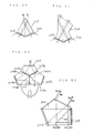
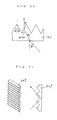
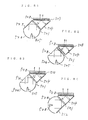
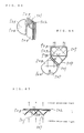
- Fig. 16 shows a polarization principle such that a plane of polarization is rotated at 90 ° by reflection on the prism reflecting surface.
- a linear polarized light 10 incident on a surface 9a is divided into a component Fs parallel to a ridgeline of a prism and a component Fp perpendicular to the ridgeline, which components are vectors of an electric field.
- the surfaces 9a and 9b are reflecting surfaces of a perfect conductor, a direction of the component Fp reflected on the surfaces 9a and 9b is inverted to provide a component Ep′ of a reflected light 11.
- a plane of polarization of the incident light 10 is rotated at 90° to provide the reflected light 11.
- the reflecting surface of the perfect conductor does not actually exist. Accordingly, a phase difference ⁇ between the component Fs′ and the component Fp′ is normally generated. Further, both the components have different amplitudes. Therefore, the reflected light 11 becomes an elliptic polarized light. Accordingly, only a component of the elliptic polarized light having a plane of polarization perpendicular to that of the incident light is effective. The smaller the phase difference ⁇ , the more the reflecting surface becomes near the perfect conductor to increase the efficiency.
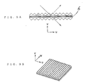
- Fig. 15 shows an example of the prism reflecting surface.
- the reflecting surface is formed of a substrate 14 having one surface formed with a plurality of reflecting mirror surfaces arranged in parallel rows in a direction d perpendicular to a ridgeline formed between the adjacent ones of the reflecting mirror surfaces.
- the adjacent reflecting mirror surfaces intersect each other at 90 ° , and each reflecting mirror surfaces is inclined at 45° with respect to a normal direction U of the substrate surface.
- the perpendicular intersection of the adjacent reflecting mirror surfaces is the condition required for the fact that an incident light entering in the normal direction U is reflected in a direction counter to the normal direction U. Further, it is most preferable from the viewpoint of efficiency that each reflecting mirror surface is inclined at 45 ° with respect to the normal direction U.
- the reflecting mirror surfaces can be formed by forming one surface of the substrate 14 into a predetermined shape and then forming a metal layer by vapor deposition or plating or a dielectric multi-layer film on the one surface of the substrate 14.
- the plane surface can be used as an incident surface
- the prism surface can be used as a back surface mirror.
- the prism surface can be used as a total reflecction surface.
- the phase difference ⁇ depends on a kind of metal, a film thickness or design of the multi-layer film.
- the phase difference ⁇ can be calculated from the refractive index.
- the refractive index is 1.49 (polymethylmethacrylate)
- the phase difference ⁇ is 70° . Accordingly, a component after rotation of a plane of polarization at 90 ° is obtained at a rate of 67 %.
- the efficiency on the reflecting surface is substantially 67 %.
- Fig. 17 shows an example of the reflecting surface constructed of a reflecting mirror 15 and a 1/4 wave plate 16 located before the reflecting mirror 15.
- An incident light 17 is transmitted through the 1/4 wave plate 16 before reflection on the reflecting mirror 15, and a reflected light 18 from the reflecting mirror 15 is transmitted again through the 1/4 wave plate 16.
- the plane of polarization of the incident light 17 is rotated at 90° to obtain the reflected light 18.
- the reflecting mirror 15 may be formed from a metal mirror or a dielectric multi-layer film.
- the reflecting surface may be a reflecting surface of a metal mirror or a dielectric multi-layer film on one surface of the 1/4 wave plate 16.
- the efficiency of obtaining the reflected light after rotation of the plane of polarization at 90 ° depends on a wavelength. Accordingly, in the case of using a white light, this construction is not preferable. To reduce such a wavelength dependency, an achromatic wave plate formed of combined double refraction materials having different wavelength dispersion properties may be used.
- Fig. 18 shows an example of the reflecting surface employing a phase plate 19 located before a prism reflecting surface 20.
- the phase difference ⁇ between the component Fs′ and the component Fp′ of the reflected light from the prism reflecting surface is not zero, and the reflected light is therefore an elliptic polarized light.
- the phase difference ⁇ can be canceled by locating the phase plate 19 for generating a total phase difference - ⁇ which is the same as the phase difference ⁇ in magnitude but inverted in sign.
- a linear polarized light with the phase difference ⁇ eliminated can be obtained.
- a retardation of the phase plate 19 is set to - ⁇ / 2.
- the phase difference to be provided by the phase plate is relatively small, the wavelength dependency is small as a whole, and a white light can be sufficiently used.
- the prism reflecting surface may be selected from the above-mentioned materials, it is most preferable to use a total reflecting prism which has a high reflectance and is advantageous in easy calculation of the phase difference ⁇ .
- the phase difference ⁇ is 70° , and accordingly the phase plate providing a retardation of 35° is used to thereby easily obtain a high efficiency over the entire wavelength region of a visible light.
- the device can be made compact and lightweight.
- the polarization beam splitter according to the present invention is realized by substituting a transparent plate formed with a plurality of prism elements for at least one of two rectangular prisms of a conventional prism type beam splitter. Accordingly, the polarization beam splitter can be made lightweight.
- the polarization beam splitter according to the present invention can be used for the applications as described in the aforementioned cited references, that is, Japanese Patent Laid-open Publication No. 63-197913, Japanese Utility Model Laid-open Publication No. 63-187101, Japanese Patent Laid-open Publication Nos. 63-271313 and 63-168622.
- Such a transmitter is constructed of a 1/2 wave plate, for example, wherein an incident light is transmitted through the 1/2 wave plate in such a manner that an angle defined between a plane of polarization of the incident light and an optic axis of the 1/2 wave plate is 45 ° .
- the 1/2 wave plate can be used in case of bidirectional light transmission.
- the 1/4 wave plate, the 1/2 wave plate and the phase plate are obtained by forming a crystal of an inorganic substance such as mica or rock crystal to a predetermined thickness or drawing a high-molecular film indicating a double refraction such as polycarbonate or polyester to a predetermined magnitude.
- the reflected or transmitted light component and/or the other light component divided by the polarizing film are reflected on reflecting means to change an advancing direction, and both the light components are then synthesized at an intersecting position thereof to obtain a single light beam.
- Expansion of the light beam width can be eliminated by arranging a light beam width reducing portion before or behind the above polarization forming means, the light beam width reducing portion comprising reflecting means and a prism formed plate having a plurality of microprisms arranged in rows.
- a preferred embodiment of claim 12 is realized by substituting the combination of a 1/4 wave plate and a plane mirror for a prism reflecting surface to be used in preferred embodiments of claims 1 to 7, 10 and 11 to be described below, and a preferred embodiment of claim 13 is realized by additionally locating a phase plate before the prism reflecting surface to be used in the preferred embodiments of claims 1 to 7, 10 and 11.
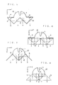
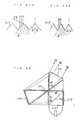
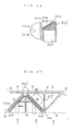
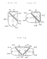
- Fig. 13 is a perspective view of the preferred embodiment of claim 2, and Fig. 1A is a plan view as seen in a direction of Z-axis in Fig. 13.
- An s-polarization component (a component having a plane of polarization parallel to a sheet of the drawing, as shown by a dashed line in Fig. 1A) of light from a light source 1 is changed in advancing direction to a positive direction of X-axis by a polarization beam splitter 2a, and outgoes therefrom.
- a p-polarization component (a component having a plane of polarization perpendicular to the sheet of the drawing, as shown by a solid line in Fig.
- Reference numeral 12 designates a curved mirror for making the rays of light from the light source 1 substantially parallel.
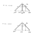
- Fig. 2A is a plan view showing the preferred embodiment of claim 3.
- An s-polarization component of light from a light source 1 is reflected on a polarization beam splitter 2 to reach a prism reflecting surface 4.
- the plane of polarization of the s-polarization component is rotated at 90 ° to obtain a p-polarization component which is in turn transmitted through the polarization beam splitter 2 to outgo in the positive direction of X-axis.
- a p-polarization component of the light from the light source 1 is transmitted through the splitter 2, and is then reflected on a reflecting mirror 5 to outgo in the positive direction of X-axis.
- a p-polarized light beam oriented in a direction perpendicular to an incident beam is obtained.
- Fig. 3A is a plan view showing the preferred embodiment of claim 4.
- An s-polarization component of light from a light source 1 is reflected on polarization beam splitters 2a and 2b to reach a prism reflecting surface 4.
- the plane of polarization of the s-polarization component is rotated at 90 ° to obtain a p-polarization component which is in turn transmitted through the polarization beam splitter 2b to outgo in the positive direction of X-axis.
- a p-polarization component of the light from the light source 1 is transmitted through the splitter 2a to outgo in the positive direction of X-axis.
- a p-polarized light beam oriented in a direction parallel to an incident beam is obtained.
- Fig. 4A is a plan view showing the preferred embodiment of claim 5.
- An s-polarization component of light from a light source 1 is reflected on a polarization beam splitter 2 to reach a prism reflecting surface 4.
- the plane of polarization is rotated at 90 ° to obtain a p-polarization component which is in turn transmitted through the polarization beam splitter 2 to reach a reflecting mirror 5.
- the p-polarization component outgoes in the positive direction of X axis.
- a p-polarization component of the light from the light source 1 is transmitted through the splitter 2 to outgo in the positive direction of X-axis.
- a p-polarized light beam oriented in a direction parallel to an incident beam.
- Fig. 5 is a plan view showing the preferred embodiment of claim 6.
- This preferred embodiment is constructed by combining two of the device of the preferred embodiment of claim 4 in symmetrical relationship with respect to an X-Z plane, and using a common light source. With this construction, a portion of the device except the light source can be reduced in volumetric size to 1/2 or less as compared with the preferred embodiment of claim 4, thus making the device greatly compact.
- Fig. 14 is a perspective view of the preferred embodiment of claim 6.
- Fig. 7 is a plan view showing the preferred embodiment of claim 7.
- This preferred embodiment is constructed by combining two of the device of the preferred embodiment of claim 5 in symmetrical relationship with respect to an X-Z plane, and using a common light source. With this construction, the device can be greatly compact as similar to the preferred embodiment shown in Fig. 5.
- Reference numeral 4′ designates two prism reflecting surfaces laminated together.
- the polarization beam splitter employable in the preferred embodiment is generally classified into a mirror type (plate type) and a prism type (cube type).
- the mirror type polarization beam splitter is formed by coating multiple layers of optical thin films on a transparent plate.
- the splitter of this type separates an s-polarization component from a p-polarization component by utilizing the fact that these components have different reflectances.
- this type splitter is superior from the viewpoint of lightness in weight, it is limitedly used for a monochromatic light because of a narrow wavelength band.
- the prism type polarization beam splitter is formed by attaching two rectangular prisms together with a multi-layer polarizing film interposed therebetween.
- the splitter of this type can be used for a substantially entire wavelength band of a visible light, that is, a white light.
- this type is inferior in lightness to the mirror type.
- the multi-layer polarizing film as mentioned above is a dielectric multi-layer film formed by alternately laminating a substance having a high refractive index and a substance having a low refractive index so as to obtain an angle of refraction equal to a Brewster's angle.
- Figs. 1A, 2A, 3A, 4A, 5 and 7 employ the mirror type polarization beam splitter
- Figs. 1B, 2B, 3B, 4B, 6 and 8 which also correspond to claims 2 to 7 employ the prism type polarization beam splitter.
- the prism type polarization beam splitter is advantageous in performance but inferior in lightness. To cope with this, both the performance and the lightness can be satisfied by the polarization beam splitters as defined in claims 8 and 9.
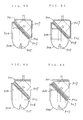
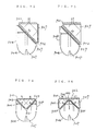
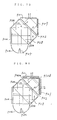
- Figs. 9A and 9B show a preferred embodiment of claim 8.
- the polarization beam splitter shown in Figs. 9A and 9B is formed by interposing a multi-layer polarizing film 6 between two transparent plates each formed with rows of rectangular prism elements.
- the multi-layer polarizing film 6 is the same as that of the prism type polarization beam splitter.
- the surfaces of each prism element formed on each transparent plate has the same function as that of the incident surface, the reflecting surface and the outgoing surface of the prism type polarization beam splitter. Consequently, the polarization beam splitter shown in Figs. 9A and 9B has the same function as that of the prism type polarization beam splitter. It is not preferable to apply the splitter as shown in Figs.
- Figs. 10A and 10B show a preferred embodiment of claim 9.
- the polarization beam splitter shown in Figs. 10A and 10B is constructed by substituting one of the transparent plates formed with the rows of the prism elements shown in Figs. 9A and 9B for one of the rectangular prisms of the prism type polarization beam splitter.
- the function of the splitter of claim 9 is the same as that of the prism type splitter and the splitter of claim 8.
- the weight of the splitter of claim 9 is about half that of the prism type splitter.
- the employment of the prism type splitter is advantageous from the viewpoints that the prisms function as a light conductor and that the manufacturing is easy. For example, it is unnecessary to adjust an angle of the splitter by setting the splitter on the basis of the prism surfaces. In this circumstance, the polarization beam splitter of claim 9 maintains one of the rectangular prisms.
- a manufacturing method of the polarization beam splitters of claims 8 and 9 is basically the same as that of the prism type splitter. That is, the multi-layer polarizing film is formed on one of the transparent plates having the prism elements or on the prism by vapor deposition or the like, and then the other transparent plate having the prism elements is bonded to the multi-layer polarizing film.
- Fig. 11 shows a preferred embodiment obtained by applying the polarization beam splitter of claim 8 to the polarization forming optical device of claim 7
- Fig. 12 shows a preferred embodiment obtained by applying the polarization beam splitter of claim 9 to the polarization forming optical device of claim 7.
- Fig. 19A shows a preferred embodiment of claim 14. This preferred embodiment is obtained by substituting a single 1/2 wave plate 22 for the two prism reflecting surfaces 4′ in the preferred embodiment shown in Fig. 7.
- an s-polarization component of light from a light source 1 incident on a right unit is reflected on a polarization beam splitter 2a, and is then transmitted through a 1/2 wave plate 22, thereby rotating the plane of polarization of the s-polarization component at 90° to obtain a p-polarized light.
- the p-polarized light enters a left unit arranged in symmetrical relationship with the right unit, and is transmitted through a polarization beam splitter 2b to reach a reflecting mirror 5.
- the p-polarized light After reflecting on the reflecting mirror 5, the p-polarized light outgoes in a positive direction of X-axis.
- a p-polarization component of the light from the light source 1 incident on the right unit is transmitted through the polarization beam splitter 2a to outgo in the positive direction of X-axis.
- an s-polarization component and a p-polarization component incident on the left unit from the light source 1 a p-polarized light beam oriented in the positive direction of X-axis can be similarly obtained.
- the 1/2 wave plate is disposed in such a manner that an optic axis thereof is inclined at 45 ° with respect to the plane of polarization, so that the rotation of the plane of polarization can be effected without dependency upon a direction of transmission of the light.
- Fig. 19B also shows a preferred embodiment of claim 14. This preferred embodiment is obtained by substituting a single 1/2 wave plate 22 for the two prism reflecting surfaces 4′ in the preferred embodiment shown in Fig. 8.
- a preferred embodiment of claim 20 is realized by substituting the combination of a 1/4 wave plate and a plane mirror for a prism reflecting surface to be used in preferred embodiments of claims 15 to 19 to be described below, and a preferred embodiment of claim 21 is realized by additionally locating a phase plate before the prism reflecting surface to be used in the preferred embodiments of claims 15 to 19.
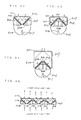
- Figs. 27, 28, 29A and 29B are plan views of the preferred embodiments of claim 15.
- rays of light from a light source 105 are made parallel by a curved mirror 102, and are incident on a mirror type polarization beam splitter 103 at an angle ⁇ .
- An p-polarization component (shown by a solid line in the drawing) of the incident light on the splitter 103 is transmitted through the polarization beam splitter 103, and is then refracted by a prism 113 to outgo therefrom.
- an s-polarization component shown by a dashed line in the drawing
- the incident light on the splitter 103 is reflected on the splitter 103 to reach a prism reflecting surface 104.
- a plane of polarization of the s-polarization component is rotated at 90° to obtain a p-polarized light which is in turn transmitted through the splitter 103. Then, the p-polarized light is refracted by the prism 113 to outgo therefrom.
- the above two outgoing light beams are parallel and adjacent to each other, and they can be therefore utilized as a single linear polarized light beam.
- a prism type polarization beam splitter 121 is substituted for the mirror type polarization beam splitter 103 used in Fig. 27. Further, as the prism type splitter is used, a pair of reflecting mirrors 122 are located between the splitter 121 and the prism 113 to obtain the same effect as that of the preferred embodiment shown in Fig. 27 .
- a prism formed plate 101 is substituted for the prism 113 used in Fig. 28.
- the prism formed plate 101 is constructed in such a manner that a lower surface of the plate 101 facing the prism type polarization beam splitter 121 is a plane surface, and an upper surface of the plate 101 is formed with a plurality of small prism elements similar to the prism 113 shown in Fig. 28, which prism elements are arranged in parallel rows. With this construction, the device can be made compact.
- a p-polarization component of light from a light source 105 is transmitted through the prism type polarization beam splitter 121, and is then reflected on a left reflecting mirror 122 to outgo from a left half portion of the prism formed plate 101.
- an s-polarization component of the light from the light source 105 enters the prism type polarization beam splitter 121, and is reflected on a polarizing film sandwiched between two rectangular prism elements of the splitter 121 to reach a prism reflecting surface 104.
- the plane of polarization of the s-polarization component Upon reflecting on the prism reflecting surface 104, the plane of polarization of the s-polarization component is rotated at 90 ° to obtain a p-polarized light which is in turn transmitted through the splitter 121, and is then reflected on a right reflecting mirror 122 to outgo from a right half portion of the prism formed plate 101.
- the plane of polarization of the s-polarization component is rotated at 90 ° to obtain a p-polarized light which is in turn transmitted through the splitter 121, and is then reflected on a right reflecting mirror 122 to outgo from a right half portion of the prism formed plate 101.
- the polarization forming optical device as defined in claims 16 to 19 to be described below is particularly compact and simple in structure, which is further improved in practical use.
- the preferred embodiment shown in Fig. 20 also corresponds to claim 17.
- Fig. 20 is realized by substituting a prism formed plate 101 similar to that shown in Figs. 29A and 29B for the prism 113 shown in Fig. 27. With this construction, the device can be greatly compact.
- the prism elements of the prism formed plate 101 are arranged in parallel rows in a direction of Y-axis.
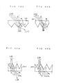
- n represents a refractive index of the prism formed plate 101
- ⁇ represents an incident angle to the prism formed plate 101. Since the incident angle ⁇ is 45° in claim 17, the following equations (2) and (3) are obtained from the above equations (1).
- sin ⁇ 1/(n ⁇ 2 1/2 ) (2)
- tan ⁇ (2n2 - 1) 1/2 - 2 1/2 (3) Since ⁇ > 0, it is understood that n > (3/2) 1/2 should hold from the equation (3).
- the refractive index of the prism formed plate is preferably selected to satisfy the above condition (4). However, even if the value of n is greater than the value obtained from the condition (4) to result in the generation of the loss light as shown in Fig. 26A, the efficiency is not rapidly reduced, provided that ⁇ ⁇ ⁇ holds.
- the refractive index n is preferably selected to satisfy the equality of the expression (4).
- Figs. 21 and 22 corresponding to claims 18 and 19, respectively are realized by applying the polarization beam splitters of claims 8 and 9, respectively, to a device similar to the preferred embodiment shown in Fig. 20 corresponding to claim 17.
- a polarization beam splitter 106 similar to that shown in Fig. 9 is employed.
- a polarization beam splitter 107 similar to that shown in Fig. 10 is employed.
- a width of the linear polarized light beam to be finally obtained is larger than that of the random polarized beam to be first obtained by the light source 105 and the curved mirror 102. Particularly in the preferred embodiments shown in Figs. 20 to 25 and 27 to 29, the width is expanded by the (1/cos ⁇ ) times in the direction of Y-axis. Accordingly, a cross section of the polarized light beam to be finally obtained tends to be elongated in the direction of Y-axis. This is not necessarily desired from the viewpoint of utilization of the polarized light beam to be finally obtained.
- prisms 123 and 125 are located before the polarization beam splitter 106, respectively, so as to suppress an increase in beam width.
- Fig. 31 shows a modification of the preferred embodiment shown in Fig. 32. That is, a polarization beam splitter 124 is substituted for the polarization beam splitter 106 used in Fig. 32.
- the polarization beam splitter 124 has a shape of quadrangular prism having a pair of trapezoidal side surfaces formed with upper and lower rows of rectangular prism elements.
- the polarization beam splitter also serves as a ligh conductor. This preferred embodiment also corresponds to claim 15.
- a preferred embodiment of claim 25 is realized by substituting the combination of a 1/4 wave plate and a plane mirror for a prism reflecting surface to be used in preferred embodiments of claims 22 to 24 to be described below, and a preferred embodiment of claim 26 is realized by additionally locating a phase plate before the prism reflecting surface to be used in the preferred embodiments of claims 22 to 24.
- Figs. 40 and 41 are plan views of the preferred embodiments of claim 22.
- rays of light from a light source 205 are made parallel by a curved mirror 206.
- the parallel rays of light are divided into two beams by a prism 221.
- Each beam enters a mirror type polarization beam splitter 203.
- a p-polarization component (shown by a solid line in the drawing) of the incident light on the splitter 203 is transmitted through the polarization beam splitter 203, and is then refracted by a prism 222 to outgo therefrom.
- an s-polarization component shown by a dashed line in the drawing
- the incident light on the splitter 203 is reflected on the splitter 203 to reach a prism reflecting surface 204.
- a plane of polarization of the s-polarization component is rotated at 90° to obtain a p-polarized light which is in turn transmitted through the splitter 203. Then, the p-polarized light is refracted by the prism 222 to outgo therefrom.
- the above four outgoing light beams are parallel and adjacent to each other, and they can be therefore utilized as a single linear polarized light beam.
- a prism type polarization beam splitter 213 is substituted for the mirror type polarization beam splitter 203 used in Fig. 40. Further, as the prism type splitter is used, a pair of reflecting mirrors 223 are located between the splitters 213 and the prism 222 to obtain the same effect as that of the preferred embodiment shown in Fig. 40.
- Figs. 33 to 35, 42 and 43 are plan views of the preferred embodiments of claim 23, and Fig. 38 is a perspective view of Fig. 33.
- the preferred embodiments of claim 23 are realized by substituting a prism formed plate for at least one of the first prism 221 and the second prism 222 shown in Figs. 40 and 41, so as to make the device compact.
- prism formed plates 202 and 201 are substituted for the prisms 221 and 222 shown in Fig. 40, respectively.
- prism formed plates 202 and 201 are substituted for the prisms 221 and 222 shown in Fig. 41, respectively.
- the prism formed plate 202 is constructed in such a manner that an upper surface of the plate 202 facing the polarization beam splitter 203 or 213 is a plane surface, and a lower surface of the plate 202 facing the light source 205 is formed with a plurality of small prism elements similar to the prism 221 shown in Fig. 40 or 41, which prism elements are arranged in parallel rows.
- the prism formed plate 201 is constructed in such a manner that a lower surface of the plate 201 facing the polarization beam splitter 203 or 213 is a plane surface, and an upper surface of the plate 201 is formed with a plurality of small prism elements similar to the prism 222 shown in Fig. 40 or 41, which prism elements are arranged in parallel rows.
- first prism 221 and the second prism 222 may be replaced by the prism formed plate 202 or 201 so as to effectively make the device compact, it is apparent that the device can be made more effectively compact by replacing both the first and second prisms 221 and 222 with the prism formed plates 202 and 201.
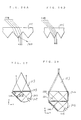
- ⁇ represents an incident angle of an incident light 224 as shown in Figs. 44A and 44B
- n1 represents a refractive index of the prism 222 or the prism formed plate 201.
- the angle ⁇ 1 is preferably set to an angle ⁇ 0 or less for making a refracted light parallel to one of the surfaces of the prism 222 or each prism element of the prism formed plate 201 as shown in Fig. 44B.
- the angle ⁇ 0 is obtained from the following equation (6).
- ⁇ 0 cos ⁇ 1 [ ⁇ 1 + (1 + 8n12) 1/2 ⁇ /4n1 ] (6)
- the angle ⁇ 2 is preferably set to an angle ⁇ 0′ or more for making the refracted light parallel to one of the surfaces of the prism 221 or each prism element of the prism formed plate 202 as shown in Fig. 45B.
- the angle ⁇ 0′ is obtained from the following equation (7) assuming that the refractive index of the prism 221 or the prism formed plate 202 is represented by n2.
- ⁇ 0′ cos ⁇ 1 [ ⁇ 1 + (1 + 8n22) 1/2 ⁇ /4n2 ] (7)
- the angles ⁇ 1 and ⁇ 2 can be decided so as to satisfy the above conditions by setting n1 ⁇ n2.
- the incident angle ⁇ can be set freely to some extent.
- the preferred embodiment shown in Fig. 34 corresponds to ⁇ > 45°
- the preferred embodiment shown in Fig. 35 corresponds to ⁇ ⁇ 45° .
- ⁇ 45° is set. Accordingly, the following conditions must hold in Fig. 45B.
- cos ⁇ 2 n2 cos( ⁇ + ⁇ 2)
- n2 sin ⁇ sin 45° ⁇ ⁇ ⁇ 2
- n2 ⁇ 1.538 is preferable.
- the preferred embodiment shown in Fig. 33 employing the mirror type polarization beam splitter is superior in compactness to the preferred embodiment shown in Fig. 42 employing the prism type polarization beam splitter.
- the light component first transmitted through the polarization beam splitter 213 from the prism formed plate 202 outgoes from an outside portion of the prism formed plate 201, and the light component secondly transmitted through the polarization beam splitter 213 after reflection on the prism reflecting surface 204 outgoes from a central portion of the prism formed plate 201.
- Such a problem can be prevented by changing a position of the prism formed plate 201 as shown in Fig. 43.
- the preferred embodiment shown in Fig. 43 is disadvantageous in compactness of the device.
- a polarization beam splitter 207 similar to that shown in Fig. 9 is employed, and the incident angle ⁇ is set to 45° , so that the device of this preferred embodiment can be used similarly to that shown in Fig. 33.
- a polarization beam splitter 208 integrally formed with a light conductor shown in Fig. 39 is employed.
- the preferred embodiment shown in Fig. 37 is different from the preferred embodiment shown in Fig. 36 in the point that an incident surface substantially contacts the prism formed plate 202, and an optical path in the device is almost present in the polarization beam splitter 208.
- a position of an incident prism surface of the polarization beam splitter 208 is not limited to the position shown in Fig. 37 but it may be located at an intermediate position between the position shown in Fig. 37 and the position shown in Fig. 36.
- a preferred embodiment of claim 28 is realized by substituting the combination of a 1/4 wave plate and a plane mirror for a prism reflecting surface to be used in preferred embodiments of claim 27, and a preferred embodiment of claim 29 is realized by additionally locating a phase plate before the prism reflecting surface to be used in the preferred embodiments of claim 27.
- Figs. 46 and 47 are plan views of the preferred embodiments of claim 27, and Fig. 48 is a perspective view of Fig. 46.
- rays of light from a li9ht source 306a are made parallel by a curved mirror 306b.
- the parallel rays of light enter a polarizing film 303.
- a p-polarization component of the incident light on the polarizing film 303 is transmitted therethrough to reach a synthesizer prism 302 consisting of a plurality of small prism elements arranged in parallel rows.
- the synthesizer prism 302 is refracted by the synthesizer prism 302 to outgo therefrom.
- an s-polarization component of the incident light on the polarizing film 303 is reflected thereon to reach a prism reflecting surface 304.
- the s-polarization component Upon reflecting on the prism reflecting surface 304, the s-polarization component is converted into a p-polarized light which is in turn transmitted through the polarizing film 303 to reach a reflecting mirror 305. After reflecting on the reflecting mirror 305 to change an advancing direction the p-polarized light reaches the synthesizer prism 302, and is refracted thereby to outgo therefrom.
- each prism element after transmission through the polarizing film 303 directly from the light source 306a is refracted by the prism element in accordance with the above equation (8), while the incident light on the other surface of the prism element after reflection on the reflecting mirror 305 is refracted by the prism element in accordance with the above equation (8), so that the advancing directions of the outgoing light beams based on both the incident light beams are made coincident with each other.
- both the outgoing light beams can be uniformly mixed with each other to thereby prevent the generation of non-uniformity of brightness and color.
- Fig. 57 shows one of the preferred embodiments of claim 27, which is realized by substituting a single prism 301 for the rows of the prism elements shown in Fig. 46.
- the preferred embodiment shown in Fig. 57 is somewhat disadvantageous as compared with the preferred embodiment shown in Fig. 46 from the viewpoints that a size of the prism is large, and that the outgoing light beam based on the transmitted light through the polarizing film 303 directly from the light source 306a is separate from the outgoing light beam based on the reflected light beam on the reflecting mirror 305 with respect to an intersection between both the surfaces of the prism 301.
- a reflectance of the s-polarized light on the polarizing film 303 is not strictly equal to a transmittance of the p-polarized light through the polarizing film 303.
- the outgoing light beam based on the reflected light from the reflecting mirror 305 is reduced in intensity due to loss on the prism reflecting surface 304, incompleteness of rotation of the plane of polarization on the prism reflecting surface 304 (depending on a wavelength) , and loss on the reflecting mirror 305 (10 - 20 % in case of Al deposition; 5 - 10 % in case of Ag deposition).
- the preferred embodiment shown in Fig. 57 is undesired from the viewpoint of non-uniformity of intensity and color of the outgoing light.
- a period of arrangement of the prism elements shown in Fig. 46 is not strictly uniform to cause the above problem.
- the non-uniformity of intensity and color of the outgoing light depends on a broadening angle of the outgoing light, it can be made almost disappear by sufficiently reducing the period of arrangement of the prism elements.
- the angle ⁇ which defines a shape of the synthesizer prism is set in the following manner.
- n cos2 ⁇ ⁇ n cos ⁇ cos ⁇ (9) ⁇ ⁇ cos ⁇ 1 [ ⁇ 1 + (1 + 8n2) 1/2 ⁇ /4n ] (10)
- the angle ⁇ is decided so as to satisfy the above expression (10) according to a refractive index n of the prism. Further, the angle ⁇ is obtained from the equation (8), so that a position and an angle of the reflecting mirror 305 can be decided.
- the smaller the angle ⁇ the larger an angle of refraction to expand a broadening angle of the outgoing light beam and thereby reduce a converging efficiency. Therefore, it is preferable from this point of view that the equality is to hold in the expression (10).
- a width of the outgoing light beam is enlarged by the (1/cos ⁇ ) times that of the incident light beam. Accordingly, the smaller the angle ⁇ , the smaller the magnitude of enlargement of the width of the outgoing light beam.
- the preferred embodiment shown in Fig. 47 is realized by exchanging the position of the light source 306a for the position of the prism reflecting surface 304 and vice versa in the preferred embodiment shown in Fig. 46.
- the preferred embodiment shown in Fig. 47 has the same function as that of the preferred embodiment shown in Fig. 46. Either the preferred embodiment shown in Fig. 46 or the preferred embodiment shown in Fig. 47 may be suitably selected according to a desired layout. However, in case of the application to a liquid crystal projector, the preferred embodiment shown in Fig. 46 is preferable since a heat source (light source) should be separate from a liquid crystal light bulb (to be located adjacent the prism 302).
- the polarizing film 303 shown in Figs. 46 and 47 is the same as that employed in a normal polarization beam splitter. That is, the polarizing film 303 is a dielectric multi-layer film formed by alternately laminating a substance having a high refractive index and a substance having a low refractive index so as to make an angle of refraction equal to a Brewster's angle. This film has a property of transmitting a p-polarized light only and reflecting an s-polarized light.
- An incident angle of the light from the light source 306a onto the polarizing film 303 is set to 45° in general. However, the incident angle is not necessarily limited to 45° . In the preferred embodiment shown in Fig.
- the incident angle is greater than 45° .
- the incident angle which can provide the best performance is dependent upon a refractive index of a transparent material to be used and a refractive index of a deposition material of the multi-layer film. Accordingly, the incident angle is not always set to 45° . However, the incident angle is practically set to 45° as similar to the normal polarization beam splitter for easiness of designing and compactness of the device.
- Figs. 46 and 47 have a mixing function as an additional function.
- an s-polarization component As (Bs) and a p-polarization component Ap (Bp) of the incident light entering one end portion of the polarizing film 303 are allowed to outgo from the prism at opposite end portions thereof.
- the outgoing light ray based on the s-polarization component and the outgoing light ray based on the p-polarization component are allowed to advance at mirror symmetrical positions with respect to a center of the outgoing beam. Accordingly, if the incident light is not uniform in brightness according to an incident position, such non-uniformity can be reduced by the above-mentioned mixing function.
- the device shown in Fig. 49 effectively utilizes the above mixing effect and further improves the compactness.
- Fig. 49 is constructed by symmetrically disposing two sets of the units each similar to the device shown in Fig. 46 (however, the light source is common), and further providing a prism 308 for synthesizing the outgoing beams from both the units.
- the mixing effect is utilized for halves of the incident beam from the light source, each half tending to be unsymmetrical in brightness. The mixing is also carried out in the prism 308.
- the prism 308 as a synthesizing means as shown in a part enclosed by a dashed line in Fig. 49 may be replaced by a single prism 309 as shown in Fig. 50 or a reflecting means 310 for making the advancing vectors coincident with each other.
- two prism reflecting surfaces 304 of both the units are disposed adjacent to each other, so that the rotation of the plane of polarization is effected by the reflection on the prism reflecting surfaces 304.
- the same function can be exhibited by replacing the two prism reflecting surfaces with a single 1/2 wave plate as defined in claim 30.
- Fig. 52 shows a preferred embodiment of claim 30.
- an s-polarization component of light from a light source incident on a right unit is reflected on a polarizing film 303a, and is then transmitted through a 1/2 wave plate 311, thereby rotating the plane of polarization of the s-polarization component at 90° to obtain a p-polarized light.
- the p-polarized light enters a left unit arranged in symmetrical relationship with the right unit, and is transmitted through a polarizing film 303b to reach a reflecting mirror 305b. After reflecting on the reflecting mirror 305b, the p-polarized light outgoes from a prism 302b, and enters a prism 308.
- a p-polarization component of the light from the light source incident on the right unit is transmitted through the polarizing film 303a to outgo from a prism 302a and enters the prism 308. Then, both the p-polarized lights are synthesized in the prism 308 to outgo therefrom. As to an incident light on the left unit from the light source, a synthesized p-polarized light beam is similarly obtained in the prism 308 to outgo therefrom.
- the 1/2 wave plate is disposed in such a manner that an optic axis thereof is inclined at 45° with respect to the plane of polarization, so that the rotation of the plane of polarization can be effected without dependency upon a direction of transmission of the light.
- the prism 308 as a synthesizing means as shown in Fig. 52 may be replaced by a single prism 309 as shown in Fig. 50 or a reflecting means 310 for making the advancing vectors coincident with each other.
- Fig. 55 shows a preferred embodiment of claim 27 using a normal polarization beam splitter.
- the preferred embodiment shown in Fig. 55 is constructed of a polarization beam splitter 318, five triangular prisms, and a transparent adhesive 317 having a low refractive index for bonding the polarization beam splitter 318 and the five triangular prisms.
- One of the five triangular prisms has a synthesizer prism 302.
- a broadening light beam is enclosed in the prisms by total reflection to form a light conductor. Therefore, the light from the light source can be efficiently conducted to the synthesizer prism 302.
- this preferred embodiment is inferior in compactness to the preferred embodiment shown in Fig. 46.
- Figs. 72, 73, 77 and 76 are plan views of preferred embodiments of claim 31. These preferred embodiments also correspond to claims 34 and 38.
- rays of light from a light source 405 are made parallel by a curved mirror 406, and enter a mirror type polarization beam splitter 427 at an incident angle of 45 ° .
- a p-polarization component of the incident light on the polarization beam splitter 427 is transmitted through the polarization beam splitter 427, and is then refracted by a first prism formed plate 402 to outgo therefrom.
- an s-polarization component of the incident light on the polarization beam splitter 427 is reflected on the polarization beam splitter 427 to reach a prism reflecting surface 404.
- a plane of polarization of the s-polarization component is rotated at 90° to obtain a p-polarized light which is in turn transmitted through the polarization beam splitter 427, and is then refracted by the first prism formed plate 402 to outgo therefrom.
- the above two outgoing light beams from the first prism formed plate 402 can be made parallel by suitably selecting a shape and a refractive index of each small prism element of the first prism formed plate 402.
- the polarization beam splitter 427, the prism reflecting surface 404 and the first prism formed plate 402 constitute the polarizing portion according to the present invention.
- a part of the outgoing light beams from the first prism formed plate 402 outgoing from a half portion of the first prism formed plate 402 enters the whole of a second prism formed plate 401 at an incident angle of 45° , and is then refracted by the second prism formed plate 401 to outgo therefrom.
- the other part of the outgoing light beams from the first prism formed plate 402 outgoing from the other half portion of the first prism formed plate 402 enters the whole of a reflecting mirror 407 at an incident angle of 45° , and is reflected on the reflecting mirror 407 to thereby change an advancing direction at 90°.
- the reflected light from the reflecting mirror 407 enters the whole of the second prism formed plate 401 at an incident angle of 45° , and is then refracted by the second prism formed plate 401 to outgo therefrom.
- the above two outgoing light beams from the second prism formed plate 401 can be made parallel by suitably selecting a shape and a refractive index of each small prism element of the second prism formed plate 401.
- a width of the total outgoing light beam from the second prism formed plate 401 is the same as that of the incident light beam from the light source 405.
- the reflecting mirror 407 and the second prism formed plate 401 constitute the light beam synthesizing portion according to the present invention.
- the first prism formed plate 402 or the second prism formed plate 401 is similar to the prism formed plate recited in claims 16 and 17, and the polarising portion corresponds to the polarization forming optical device of claim 17.
- the preferred embodiment shown in Fig. 77 is realized by merely changing positions of the light source 405, the curved mirror 406 and the reflecting mirror 407 shown in Fig. 72. Accordingly, the function of the preferred embodiment shown in Fig. 77 is the same as that of the preferred embodiment shown in Fig. 72.
- the reflecting mirror 407 employed in Figs. 72 and 77 is formed from a metal mirror or a dielectric multi-layer film.
- the reflecting mirror 407 may be a total reflecting mirror utilizing that the incident angle and the reflection angle are 45 ° . That is, the total reflecting mirror is constructed of a transparent plate having a refractive index of 2 1/2 or more and a plurality of rectangular prism elements arranged in parallel rows formed on one surface of the transparent plate.
- Figs. 73 and 76 utilize such a total reflecting mirror.
- a single rectangular prism 431 is provided for the total reflecting mirror.
- a single rectangular prism 409 formed with a plurality of prism element rows on the light outgoing surface is provided to face the first prism formed plate 402, so that the prism 409 also serves as a light conductor for the whole outgoing light from the first prism formed plate 402.
- Figs. 79 and 80 are plan views of preferred embodiments of claims 31 and 32.
- a prism type polarization beam splitter 429 is employed.
- two reflecting mirrors 428 are employed. Each of the two reflecting mirrors 428 functions to guide a half part of an outgoing light beam from one of two outgoing surfaces of the prism type polarization beam splitter 429 to a half portion of the first prism formed plate 402.
- Each reflecting mirror 428 is suitably selected from a mirror similar to the reflecting mirror 407 shown in Figs. 72 and 77, a total reflecting mirror as shown in Fig. 71, or a mirror similar to the rectangular prism 431 shown in Fig. 76.
- the preferred embodiment shown in Fig. 80 employs two second prism formed plates 401 and two dichroic mirrors 430a and 430b to have a function of color separation by utilizing a wide band property of the prism type polarization beam splitter.
- the dichroic mirror 430a is a mirror which transmits a red light and reflects green and blue lights
- the dichroic mirror 430b is a mirror which transmits green and blue lights and reflects a red light
- a red polarized light and a cyan polarized light are obtained, respectively.
- Figs. 58 and 61 are plan views of preferred embodiments of claims 31 and 39.
- the preferred embodiments shown in Figs. 58 and 61 are realized by replacing the mirror type polarization beam splitter 427 shown in Figs. 72 and 73 with the polarization beam splitter of claim 8, respectively. That is, a polarization beam splitter 403 shown in Figs. 58 and 61 is the same as the polarization beam splitter shown in Fig. 9.
- Figs. 59 and 60 are plan views of preferred embodiments of claims 31 and 40, and Fig. 66 is a perspective view of Fig. 59.
- a polarization beam splitter 408 is the same as the polarization beam splitter shown in Fig. 10.
- Figs. 74 and 78 are plan views of preferred embodiments of claims 33, 34 and 38.
- two of the polarizing portion shown in Fig. 72 are arranged symmetrically so as to inwardly orient two outgoing light beams from the two polarizing portions.
- a second prism formed plate 401 is located at a position where the two outgoing light beams from the two polarizing portions intersect each other. The two outgoing light beams intersected above are synthesized by the prism formed plate 401.
- the reflecting mirror 407 is eliminated in the preferred embodiment of Fig. 74, and an overall volume for obtaining the same cross section of the outgoing light beam as that in the preferred embodiment of Fig. 72 can be reduced to about 1/2.
- the preferred embodiment of Fig. 74 has a mixing function such that right and left portions of the incident light beam from the light source are mixed together on the outgoing surface of the prism formed plate 401 to thereby reduce non-uniformity of light quantity in the cross section of the incident light beam.
- the preferred embodiment shown in Fig. 78 is realized by changing positions of the light source 405, the curved mirror 406 and the prism reflecting surfaces 404 shown in Fig. 74 and providing two of the light source 405 and the curved mirror 406.
- each of the incident light beams from the two light sources 405 is allowed to outgo from the whole surface of the prism formed plate 401. Accordingly, even when one of the two light sources 405 is turned off, a distribution of the outgoing light beam is not almost changed but an intensity only is reduced.
- the intensity of the outgoing light beam can be changed in two or three stages (e.g., in the case of using two light sources having high and low intensities, three stages consisting of the low intensity only, the high intensity only and the low intensity plus the high intensity can be individually obtained by switching the two light sources).
- a tint of the outgoing light can be changed.
- Fig. 75 is a plan view of a preferred embodiment of claims 37 and 38.
- two of the device shown in Fig. 72 are arranged symmetrically with respect to a plane of the prism reflecting surface, and a single 1/2 wave plate 410 is substituted for the prism reflecting surface 404 shown in Fig. 72.
- the light source 405, the curved mirror 406 and the second prism formed plate 401 are commonly used for the right and left polarizing portions.
- the device can be made compact as similar to the preferred embodiment shown in Fig. 74.
- Fig. 62 is a plan view of a preferred embodiment of claims 33, 34 and 40
- Figs. 63 and 64 are plan views of preferred embodiments of claims 37 and 40.
- a polarization beam splitter 408 is the same as the polarization beam splitter shown in Fig. 10. Accordingly, the device can be made compact as similar to the case of using a mirror type polarization beam splitter.
- the preferred embodiment shown in Fig. 64 is realized by changing a position of the second prism formed plate 401 shown in Fi9. 63. With this construction, the outgoing light beams from the right and left polarizing portions are mixed together to thereby improve the mixing effect.
- a phase plate may be located before the prism reflecting surface to obtain a preferred embodiment of claim 35.
- the prism reflecting surface may be replaced by the combination of a 1/4 wave plate and a plane mirror to obtain a preferred embodiment of claim 36.
- Fig. 65 shows a preferred embodiment of claim 41.
- the preferred embodiment of claim 41 is realized by arranging a plurality of the polarizing portion described in claim 31 and/or the polarizing portion described in claim 37, so as to reduce an overall volume required for obtaining the same cross section of an outgoing light beam. This preferred embodiment is effective particularly in the case of obtaining a wide beam.
- two of the polarizing portion shown in Fig. 63 are located at a central portion of the device, and two of the polarizing portion shown in Fig. 59 are located at opposite ends of the device. Further, a single common second prism formed plate 401 is located.
- an overall volume of the device for obtaining the same cross section of an outgoing light beam as that in the preferred embodiment of Figs. 62 and 63 can be reduced to about 1/3.
- such an overall volume in comparison with the preferred embodiment of Figs. 58 to 61 can be reduced to about 1/6.
- the number of parts can be reduced since the reflecting mirrors 407 are eliminated, and the prism formed plate 401 is commonly used.
- the constitutional elements to be arranged in a given width can be increased in number and reduced in thickness by reducing the thicknesses of the prism formed plates, the prism reflecting surfaces, the polarization beam splitters as far as the accuracy and the strength are permitted.
- Fig. 67 is a partial plan view of another preferred embodiment of claim 41.
- a plurality of polarizing portions B and light beam synthesizing portions A are repeatedly arranged.
- Some examples of the polarizing portion B are shown in Figs. 69A to 69F, and some examples of the light beam synthesizing portion A are shown in Figs. 68A to 68D.
- the same parts as those of the previous preferred embodiments are designated by the same reference numerals.
- reference numeral 412 designates a 1/4 wave plate
- reference numeral 413 designates a plane mirror.
- the plane mirror 413 may be replaced by a semi-transparent mirror, provided that optic axes of both the 1/4 wave plates are made coincident.
- the two 1/4 wave plates operate as a 1/2 wave plate as to a transmitted light.
- reference numeral 409W designates a light conductor formed by integrating the two light conductors 409.
- the outgoing light beams from the adjacent polarizing portions are mixed to exhibit the mixing effect.
- the example of Fig. 68C similar to Fig. 67 has no mixing function.
- a plurality of semi-transparent mirrors 411 are provided in the light conductor, so as to facilitate the mixing effect.
- the outgoing light beams from different positions in the adjacent polarizing portions are mixed to generate a uniform outgoing light beam.
- Fig. 81 is a plan view of a preferred embodiment of claim 42
- Fig. 85 is a perspective view of Fig. 81.
- rays of light from a light source 505 are made parallel by a curved mirror 506.
- a half portion of the parallel rays from the light source 505 enters the whole of a first prism formed plate 501 at an incident angle of 45 ° , and is then refracted by the first prism formed plate 501 to outgo therefrom.
- the other half portion of the parallel rays from the light source 505 enters the whole of a reflecting member 507 at an incident angle of 45° , and is reflected thereon to change an advancing direction at 90° .
- the reflected light from the reflecting member 507 enters the whole of the first prism formed plate 501 at an incident angle of 45° , and is then refracted by the first prism formed plate 501 to outgo therefrom.
- the above two outgoing light beams can be made parallel by suitably selecting a shape and a refractive index of each small prism element of the first prism formed plate 501.
- a beam width of the outgoing light from the first prism formed plate 501 is reduced to 1/(2) 1/2 of a beam width of the incident light from the light source 505.
- the first prism formed plate 501 and the reflecting member 507 constitute the light beam width reducing portion according to the present invention.
- the outgoing light beam from the first prism formed plate 501 enters a mirror type polarization beam splitter 503 at an incident angle of 45 ° .
- a p-polarization component of the incident light on the polarization beam splitter 503 is transmitted therethrough, and is then refracted by a second prism formed plate 502 to outgo therefrom.
- an s-polarization component of the incident light on the polarization beam splitter 503 is reflected thereon to enter a prism reflecting surface 504.
- a plane of polarization of the s-polarization component is rotated at 90° to obtain a p-polarized light which is in turn transmitted through the polarization beam splitter 503, and is then refracted by the second prism formed plate 502 to outgo therefrom.
- the above two outgoing light beams from the second prism formed plate 502 can be made parallel by suitably selecting a shape and a refractive index of each small prism element of the second prism formed plate 502.
- the polarization beam splitter 503, the prism reflecting surface 504 and the second prism formed plate 502 constitute the polarizing portion according to the present invention. While a beam width of the outgoing light from the polarizing portion is expanded to (2) 1/2 of the beam width of the outgoing light from the light beam width reducing portion, the former is the same as the beam width of the incident light to the light beam width reducing portion.
- Fig. 86 is a plan view of a preferred embodiment of claim 43.
- a prism type polarization beam splitter 513 is used in substitution for the mirror type polarization beam splitter 503 shown in Fig. 81, and two reflecting members 507 are provided. A half portion of an outgoing light from one of two outgoing surfaces of the prism type polarization beam splitter 513 is reflected on each reflecting member 507 to reach the second prism formed plate 502.
- a beam width of the outgoing light from the polarizing portion can be made equal to that of the incident light to the light beam width reducing portion.
- a light conductor 509 of a rectangular prism having one side surface formed with a plurality of small rectangular prism elements arranged in rows is employed, and the other side surface of the rectangular prism is used as the reflecting member according to the present invention which is a total reflecting surface.
- the prism reflecting surface 504 is used as the reflecting means according to the present invention (claim 44).
- a phase plate may be located before the prism reflecting surface as the reflecting means (claim 45), or a combination of a 1/4 wave plate and a plane mirror may be used as the reflecting means (claim 46).
- Figs. 83 and 84 are plan views of preferred embodiments of claim 47.
- a polarization beam splitter 510 is identical with the polarization beam splitter shown in Fig. 9.
- a slant surface of a rectangular prism 511 is used as the reflecting member in the light beam width reducing portion according to the present invention.
- a trasparent plate 512 similar to that shown in Fig. 71 is used as the reflecting member in the light beam width reducing portion according to the present invention.
- the prism 511 and the trasparent plate 512 have a refractive index of (2) 1/2 or more.
- Fig. 82 is a plan view of a preferred embodiment of claim 48.
- a polarization beam splitter 508 is identical with the polarization beam splitter shown in Fig. 10.
- a preferred embodiment shown in Fig. 87 is realized by juxtaposing a plurality of the device shown in Fig. 81.
- a single second prism formed plate 502 and a single polarization beam splitter 503 are commonly used for the plural repeated units. Accordingly, a total volume of the device can be greatly reduced to thereby obtain a compact and lightweight device.
- a preferred embodiment shown in Fig. 89 is realized by separating the light beam width reducing portion from the polarizing portion shown in Fig. 87.
- Fig. 88 is a plan view of a preferred embodiment of claim 49. This preferred embodiment is realized by juxtaposing a plurality of the device shown in Fig. 86 and eliminating the reflecting members 507.
- a single second prism formed plate 502 is commonly used for the plural repeated units, so that different incident light beams to the plural light beam width reducing portions are synthesized by the single second prism formed plate 502.
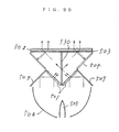
- Fig. 90 is a plan view of a preferred embodiment of claim 50.
- two of the light beam width reducing portion of the device shown in Fig. 81 are symmetrically juxtaposed in such a manner that the two first prism formed plates 501 are arranged adjacent to each other.
- a semi-transparent mirror 530 is located at a position of a symmetrical plane between the two first prism formed plates 501. Accordingly, an outgoing light from each first prism formed plate 501 enters each surface of the semi-transparent mirror 530, and a transmitted light and a reflected light from the semi-transparent mirror 530 on each side thereof are joined together to be conducted to the polarizing portion.
- the light beams from the two light beam width reducing portions are divided to reach the two polrizing portions. Therefore, even when there exists non-uniformity of brightness of the incident light to the right and left light beam width reducing portions from the light source 505 due to unsymmetry of the light source 505 or the curved mirror 506 with respect to the above-mentioned symmetrical plane (e.g., slippage of a position of a fillament of the light source 505 from the symmetrical plane to either a right side or a left side), such non-uniformity of brightness can be canceled to obtain an uniform outgoing light beam.
- a symmetrical plane e.g., slippage of a position of a fillament of the light source 505 from the symmetrical plane to either a right side or a left side
- the light source employed in the above-mentioned preferred embodiments is a beam light source using a curved mirror, it is to be easily understood that a beam light source using a lens may be employed as the light source according to the present invention.
- a linear polarized light can be efficiently formed from a random polarized light source by using a compact and simple device.
- a linear polarized light can be efficiently formed from a random polarized light source by using a compact and simple device as suppressing the expansion of a beam width and the generation of non-uniformity of brightness.
- a linear polarized light can be efficiently formed from a random polarized light source without expanding a beam width by using a compact and simple device.
- An optical device for forming a linear polarized light by dividing a light beam from a light source into two linear polarized light components, and rotating a plane of polarization of one of the light components at 90 ° to follow joining of both the light components. Further, a polarization beam splitter for dividing a light beam into two linear polarized light components is employed in such an optical device.
Landscapes
- Physics & Mathematics (AREA)
- General Physics & Mathematics (AREA)
- Optics & Photonics (AREA)
- Polarising Elements (AREA)
Applications Claiming Priority (10)
| Application Number | Priority Date | Filing Date | Title |
|---|---|---|---|
| JP265112/89 | 1989-10-13 | ||
| JP26511289A JPH03126910A (ja) | 1989-10-13 | 1989-10-13 | 偏光光源装置及び偏光ビームスプリッター |
| JP1294899A JPH03156421A (ja) | 1989-11-15 | 1989-11-15 | 偏光光源装置 |
| JP294899/89 | 1989-11-15 | ||
| JP298122/89 | 1989-11-16 | ||
| JP1298122A JPH03157621A (ja) | 1989-11-16 | 1989-11-16 | 偏光光源装置 |
| JP14452890A JPH0437817A (ja) | 1990-06-04 | 1990-06-04 | 偏光作成光学装置 |
| JP144528/90 | 1990-06-04 | ||
| JP16824690A JPH0458214A (ja) | 1990-06-28 | 1990-06-28 | 偏光作成光学装置 |
| JP168246/90 | 1990-06-28 |
Publications (2)
| Publication Number | Publication Date |
|---|---|
| EP0422661A2 true EP0422661A2 (de) | 1991-04-17 |
| EP0422661A3 EP0422661A3 (en) | 1992-07-01 |
Family
ID=27527712
Family Applications (1)
| Application Number | Title | Priority Date | Filing Date |
|---|---|---|---|
| EP19900119539 Withdrawn EP0422661A3 (en) | 1989-10-13 | 1990-10-11 | Polarization forming optical device and polarization beam splitter |
Country Status (2)
| Country | Link |
|---|---|
| US (1) | US5124841A (de) |
| EP (1) | EP0422661A3 (de) |
Cited By (18)
| Publication number | Priority date | Publication date | Assignee | Title |
|---|---|---|---|---|
| EP0460241A4 (en) * | 1989-12-26 | 1992-06-24 | Mitsubishi Rayon Co., Ltd. | Optical apparatus for generating polarized light |
| EP0470369A3 (en) * | 1990-08-08 | 1992-09-02 | Grundig E.M.V. Elektro-Mechanische Versuchsanstalt Max Grundig Hollaend. Stiftung & Co. Kg. | Projecting unit for large picture projection |
| FR2685100A1 (fr) * | 1991-12-17 | 1993-06-18 | Thomson Csf | Separateur de polarisations optique et application a un systeme de visualisation. |
| US5317349A (en) * | 1993-06-29 | 1994-05-31 | Minnesota Mining And Manufacturing Company | Overhead projector with achromatic fresnel lens |
| EP0600728A1 (de) * | 1992-12-03 | 1994-06-08 | Matsushita Electric Industrial Co., Ltd. | Polarisationsebenenrotator anwendbar für Polarisationskonverter und Projektionsanzeigesysteme |
| US5422756A (en) * | 1992-05-18 | 1995-06-06 | Minnesota Mining And Manufacturing Company | Backlighting system using a retroreflecting polarizer |
| US5452128A (en) * | 1992-01-21 | 1995-09-19 | Canon Kabushiki Kaisha | Polarization illumination apparatus and projector using the apparatus |
| US5504544A (en) * | 1994-11-23 | 1996-04-02 | Minnesota Mining And Manufacturing Company | Projector with multiple lamp light source |
| US5559634A (en) * | 1991-06-13 | 1996-09-24 | Minnesota Mining And Manufacturing Company | Retroreflecting polarizer |
| FR2735875A1 (fr) * | 1995-06-21 | 1996-12-27 | Thomson Multimedia Sa | Dispositif optique de polarisation et systeme de projection du type a valve a cristaux liquides utilisant un tel dispositif optique |
| US5650873A (en) * | 1995-01-30 | 1997-07-22 | Lockheed Missiles & Space Company, Inc. | Micropolarization apparatus |
| WO1998043225A3 (en) * | 1997-03-25 | 1999-02-25 | Sharp Kk | Optical device for polarization conversion and projection display using said device |
| EP0849619B1 (de) * | 1996-12-18 | 2003-11-05 | Seiko Epson Corporation | Optisches Element und seine Verwendung |
| US6721096B2 (en) | 1997-10-28 | 2004-04-13 | 3M Innovative Properties Company | Polarizing beam splitter |
| GB2408588A (en) * | 2003-11-27 | 2005-06-01 | Sharp Kk | Polarisation conversion optical system eg with dispersion compensation for liquid crystal projection |
| US7083847B2 (en) | 1993-12-21 | 2006-08-01 | 3M Innovative Properties Company | Optical film |
| US7652820B2 (en) | 1997-10-28 | 2010-01-26 | 3M Innovative Properties Company | Reflective LCD projection system using wide-angle cartesian polarizing beam splitter and color separation and recombination prisms |
| CN102645281A (zh) * | 2012-04-26 | 2012-08-22 | 暨南大学 | 一种利用起偏分束棱镜测量偏振度的方法 |
Families Citing this family (60)
| Publication number | Priority date | Publication date | Assignee | Title |
|---|---|---|---|---|
| JP2823649B2 (ja) * | 1990-04-05 | 1998-11-11 | 旭光学工業株式会社 | 光束合成装置 |
| FR2669744B1 (fr) * | 1990-11-23 | 1994-03-25 | Thomson Csf | Dispositif d'eclairage et application a un dispositif de visualisation. |
| US5387953A (en) * | 1990-12-27 | 1995-02-07 | Canon Kabushiki Kaisha | Polarization illumination device and projector having the same |
| JP2913864B2 (ja) * | 1991-03-04 | 1999-06-28 | 株式会社日立製作所 | 偏光変換光学系及び偏光ビームスプリッタ及び液晶表示装置 |
| JP3273955B2 (ja) * | 1991-04-09 | 2002-04-15 | キヤノン株式会社 | 画像投影装置 |
| US5381278A (en) * | 1991-05-07 | 1995-01-10 | Canon Kabushiki Kaisha | Polarization conversion unit, polarization illumination apparatus provided with the unit, and projector provided with the apparatus |
| DE4128469C2 (de) * | 1991-08-28 | 1997-12-18 | Hell Ag Linotype | Strahlteiler-Vorrichtung |
| JPH05150191A (ja) * | 1991-12-02 | 1993-06-18 | Nippon Avionics Co Ltd | 直線偏光変換装置 |
| US5384659A (en) * | 1992-04-20 | 1995-01-24 | Mitsubishi Denki Kabushiki Kaisha | Condenser lens, polarizing element, light source apparatus, and projection display apparatus |
| US5303083A (en) * | 1992-08-26 | 1994-04-12 | Hughes Aircraft Company | Polarized light recovery |
| JPH0694902A (ja) * | 1992-09-11 | 1994-04-08 | Canon Inc | 光学素子,光源,液晶光学素子,偏光照明装置,照明光学装置,偏光分離素子,偏光素子,画像投影装置および立体像表示方法 |
| USRE37377E1 (en) | 1992-10-09 | 2001-09-18 | Asahi Glass Company, Ltd. | LCD device including an illumination device having a polarized light separating sheet between a light guide and the display |
| JPH06138413A (ja) * | 1992-10-29 | 1994-05-20 | Canon Inc | プレート型偏光分離装置及び該偏光分離装置を用いた偏光照明装置 |
| US5394253A (en) * | 1993-04-06 | 1995-02-28 | Kelly; Shawn L. | Flat polarizing nonabsorbing beam splitter |
| EP0962807B1 (de) | 1993-12-21 | 2008-12-03 | Minnesota Mining And Manufacturing Company | Mehrschichtiger optischer Film |
| US6025897A (en) * | 1993-12-21 | 2000-02-15 | 3M Innovative Properties Co. | Display with reflective polarizer and randomizing cavity |
| US6096375A (en) * | 1993-12-21 | 2000-08-01 | 3M Innovative Properties Company | Optical polarizer |
| US5828488A (en) * | 1993-12-21 | 1998-10-27 | Minnesota Mining And Manufacturing Co. | Reflective polarizer display |
| US20070091230A1 (en) * | 1993-12-21 | 2007-04-26 | 3M Innovative Properties Company | Display incorporating reflective polarizer |
| US6804058B1 (en) | 1993-12-21 | 2004-10-12 | 3M Innovative Properties Company | Electroluminescent light source and display incorporating same |
| JP2738324B2 (ja) * | 1995-01-23 | 1998-04-08 | 日本電気株式会社 | 投写型液晶表示装置 |
| US5594591A (en) * | 1995-02-01 | 1997-01-14 | Pioneer Electronic Corporation | Prism system and a liquid crystal projection device |
| FR2733601B1 (fr) * | 1995-04-28 | 1997-06-27 | Thomson Multimedia Sa | Dispositif de separation de polarisation et application a un systeme d'eclairement d'un ecran a cristal liquide |
| US6088067A (en) * | 1995-06-26 | 2000-07-11 | 3M Innovative Properties Company | Liquid crystal display projection system using multilayer optical film polarizers |
| DE19649229A1 (de) * | 1995-11-28 | 1997-06-05 | Hughes Aircraft Co | Polarisationsvorrichtung |
| US5995284A (en) * | 1996-03-29 | 1999-11-30 | 3M Innovative Properties Company | Polarized illumination system for LCD projector |
| WO1998015855A1 (en) * | 1996-10-08 | 1998-04-16 | Corning Incorporated | Converter of natural white light into light with planar polarization |
| FR2758890B1 (fr) * | 1997-01-29 | 1999-02-26 | Thomson Multimedia Sa | Dispositif optique de polarisation |
| US6487016B1 (en) * | 1997-08-26 | 2002-11-26 | Matsushita Electric Industrial Co., Ltd. | Optical head |
| US5973833A (en) * | 1997-08-29 | 1999-10-26 | Lightware, Inc. | High efficiency polarizing converter |
| US5943168A (en) * | 1997-09-11 | 1999-08-24 | Hughes-Jvc Technology Corporation | Sawtooth interleave polarization combiner |
| US5940149A (en) * | 1997-12-11 | 1999-08-17 | Minnesota Mining And Manufacturing Company | Planar polarizer for LCD projectors |
| US6147953A (en) * | 1998-03-25 | 2000-11-14 | Duncan Technologies, Inc. | Optical signal transmission apparatus |
| US5986815A (en) * | 1998-05-15 | 1999-11-16 | Optical Coating Laboratory, Inc. | Systems, methods and apparatus for improving the contrast ratio in reflective imaging systems utilizing color splitters |
| US6104536A (en) * | 1998-09-18 | 2000-08-15 | 3M Innovative Properties Company | High efficiency polarization converter including input and output lenslet arrays |
| US6271968B1 (en) * | 1998-11-30 | 2001-08-07 | National Research Council Of Canada | Cut-off filters |
| US6398364B1 (en) | 1999-10-06 | 2002-06-04 | Optical Coating Laboratory, Inc. | Off-axis image projection display system |
| US7196849B2 (en) * | 2003-05-22 | 2007-03-27 | Optical Research Associates | Apparatus and methods for illuminating optical systems |
| WO2004106983A2 (en) * | 2003-05-22 | 2004-12-09 | Optical Research Associates | Illumination in optical systems |
| WO2004106982A2 (en) * | 2003-05-22 | 2004-12-09 | Optical Research Associates | Optical combiner designs and head mounted displays |
| US7306344B2 (en) * | 2003-06-10 | 2007-12-11 | Abu-Ageel Nayef M | Light guide array, fabrication methods and optical system employing same |
| US7301701B2 (en) * | 2003-06-10 | 2007-11-27 | Abu-Ageel Nayef M | Compact polarization conversion system for optical displays |
| WO2005084256A2 (en) * | 2004-02-27 | 2005-09-15 | Luxint, Inc. | Compact polarization conversion system for optical displays |
| EP1792225A4 (de) | 2004-09-01 | 2010-07-28 | Optical Res Associates | Kompakte kopfmontierte anzeigevorrichtungen mit geneigtem/dezentriertem linsenelement |
| US7450310B2 (en) * | 2005-05-03 | 2008-11-11 | Optical Research Associates | Head mounted display devices |
| JP2007322584A (ja) * | 2006-05-31 | 2007-12-13 | Sanyo Electric Co Ltd | 照明装置及びそれを用いた投写型映像表示装置 |
| US20080030974A1 (en) * | 2006-08-02 | 2008-02-07 | Abu-Ageel Nayef M | LED-Based Illumination System |
| US8755113B2 (en) | 2006-08-31 | 2014-06-17 | Moxtek, Inc. | Durable, inorganic, absorptive, ultra-violet, grid polarizer |
| US8422132B2 (en) * | 2008-12-02 | 2013-04-16 | Shanghai Lexvu Opto Microelectronics Technology Co., Ltd. | Integrated planar polarizing device |
| US20100202129A1 (en) * | 2009-01-21 | 2010-08-12 | Abu-Ageel Nayef M | Illumination system utilizing wavelength conversion materials and light recycling |
| US20110216408A1 (en) * | 2010-03-05 | 2011-09-08 | Chang-Ching Tsai | Linearly polarized light converter |
| US8611007B2 (en) | 2010-09-21 | 2013-12-17 | Moxtek, Inc. | Fine pitch wire grid polarizer |
| TWI514045B (zh) * | 2011-12-08 | 2015-12-21 | Lms Co Ltd | 多層光學片組件 |
| KR20150024416A (ko) | 2012-06-27 | 2015-03-06 | 쓰리엠 이노베이티브 프로퍼티즈 컴파니 | 광학 컴포넌트 어레이 |
| US9354374B2 (en) | 2013-10-24 | 2016-05-31 | Moxtek, Inc. | Polarizer with wire pair over rib |
| US11061233B2 (en) | 2015-06-30 | 2021-07-13 | 3M Innovative Properties Company | Polarizing beam splitter and illuminator including same |
| JP6848451B2 (ja) * | 2017-01-12 | 2021-03-24 | 富士通オプティカルコンポーネンツ株式会社 | 偏波結合装置および光変調装置 |
| CN212009182U (zh) * | 2019-11-20 | 2020-11-24 | 三赢科技(深圳)有限公司 | 光投射装置和电子装置 |
| CN112327415A (zh) * | 2020-10-12 | 2021-02-05 | 易锐光电科技(安徽)有限公司 | 波分复用结构 |
| US11733534B2 (en) | 2021-01-21 | 2023-08-22 | AdlOptica Optical Systems GmbH | Optics for formation of multiple light spots with controlled spot intensity and variable spot pattern geometry |
Family Cites Families (14)
| Publication number | Priority date | Publication date | Assignee | Title |
|---|---|---|---|---|
| US2748659A (en) * | 1951-02-26 | 1956-06-05 | Jenaer Glaswerk Schott & Gen | Light source, searchlight or the like for polarized light |
| GB743502A (en) * | 1952-05-17 | 1956-01-18 | Carl Zeiss Shiftung | Polarizer for producing uniformly polarized light with aid of interference polarizers and phase retarders |
| GB793502A (en) * | 1955-07-10 | 1958-04-16 | Tesla Radio Corp Of South Afri | Improvements in record-changing apparatus for phonographs |
| US3510198A (en) * | 1967-05-17 | 1970-05-05 | North American Rockwell | Polarizing beam-splitter having improved contrast ratio |
| US3563633A (en) * | 1968-06-27 | 1971-02-16 | Eastman Kodak Co | Phase-compensated trihedral reflectors for interferometer systems |
| CH558023A (de) * | 1972-08-29 | 1975-01-15 | Battelle Memorial Institute | Polarisationsvorrichtung. |
| NL8104123A (nl) * | 1981-09-07 | 1983-04-05 | Philips Nv | Optische multiplex- en demultiplexinrichting. |
| US4502783A (en) * | 1981-12-03 | 1985-03-05 | Hughes Aircraft Company | Alignment stabilization prism |
| JPS6319791A (ja) * | 1986-07-10 | 1988-01-27 | 松下電器産業株式会社 | マグネトロン用電源装置 |
| DE3627198A1 (de) * | 1986-08-11 | 1988-02-18 | Bbc Brown Boveri & Cie | Anordnung zur zeitlich aufgeloesten optischen rueckstreumessung an lichtwellenleitern |
| JPS63168622A (ja) * | 1987-01-05 | 1988-07-12 | Canon Inc | 光偏向素子 |
| JPS63271313A (ja) * | 1987-04-30 | 1988-11-09 | Nikon Corp | 偏光器 |
| US4798448A (en) * | 1988-02-16 | 1989-01-17 | General Electric Company | High efficiency illumination system for display devices |
| US4948229A (en) * | 1988-03-18 | 1990-08-14 | The United States Of America As Represented By The Secretary Of The Air Force | Optical switches using ferroelectric liquid crystals |
-
1990
- 1990-10-11 EP EP19900119539 patent/EP0422661A3/en not_active Withdrawn
- 1990-10-15 US US07/597,819 patent/US5124841A/en not_active Expired - Fee Related
Cited By (27)
| Publication number | Priority date | Publication date | Assignee | Title |
|---|---|---|---|---|
| EP0460241A4 (en) * | 1989-12-26 | 1992-06-24 | Mitsubishi Rayon Co., Ltd. | Optical apparatus for generating polarized light |
| EP0470369A3 (en) * | 1990-08-08 | 1992-09-02 | Grundig E.M.V. Elektro-Mechanische Versuchsanstalt Max Grundig Hollaend. Stiftung & Co. Kg. | Projecting unit for large picture projection |
| US5559634A (en) * | 1991-06-13 | 1996-09-24 | Minnesota Mining And Manufacturing Company | Retroreflecting polarizer |
| US5410421A (en) * | 1991-12-17 | 1995-04-25 | Thomson-Csf | Optical separator of polarizations and application to a display system |
| EP0547949A1 (de) * | 1991-12-17 | 1993-06-23 | Thomson-Csf | Optischer Polarisationsstrahlenteiler und seine Verwendung in einem Abbildungssystem |
| FR2685100A1 (fr) * | 1991-12-17 | 1993-06-18 | Thomson Csf | Separateur de polarisations optique et application a un systeme de visualisation. |
| US5452128A (en) * | 1992-01-21 | 1995-09-19 | Canon Kabushiki Kaisha | Polarization illumination apparatus and projector using the apparatus |
| US5422756A (en) * | 1992-05-18 | 1995-06-06 | Minnesota Mining And Manufacturing Company | Backlighting system using a retroreflecting polarizer |
| EP0600728A1 (de) * | 1992-12-03 | 1994-06-08 | Matsushita Electric Industrial Co., Ltd. | Polarisationsebenenrotator anwendbar für Polarisationskonverter und Projektionsanzeigesysteme |
| US5657160A (en) * | 1992-12-03 | 1997-08-12 | Matsushita Electric Industrial Co., Ltd. | Polarization plane rotator applicable to polarization converter and projection display system |
| US5317349A (en) * | 1993-06-29 | 1994-05-31 | Minnesota Mining And Manufacturing Company | Overhead projector with achromatic fresnel lens |
| US7083847B2 (en) | 1993-12-21 | 2006-08-01 | 3M Innovative Properties Company | Optical film |
| US5504544A (en) * | 1994-11-23 | 1996-04-02 | Minnesota Mining And Manufacturing Company | Projector with multiple lamp light source |
| US5650873A (en) * | 1995-01-30 | 1997-07-22 | Lockheed Missiles & Space Company, Inc. | Micropolarization apparatus |
| EP0757274A1 (de) * | 1995-06-21 | 1997-02-05 | THOMSON multimedia | Optische Polarisationsvorrichtung und Flüssigkristall-Projektionssystem damit |
| US5900973A (en) * | 1995-06-21 | 1999-05-04 | Thomson Multimedia S.A. | Optical polarization device and projection system of liquid crystal valve type utilizing such a device |
| FR2735875A1 (fr) * | 1995-06-21 | 1996-12-27 | Thomson Multimedia Sa | Dispositif optique de polarisation et systeme de projection du type a valve a cristaux liquides utilisant un tel dispositif optique |
| EP0849619B1 (de) * | 1996-12-18 | 2003-11-05 | Seiko Epson Corporation | Optisches Element und seine Verwendung |
| USRE39243E1 (en) | 1996-12-18 | 2006-08-22 | Seiko Epson Corporation | Optical element, polarization illumination device, and projector |
| USRE40251E1 (en) | 1996-12-18 | 2008-04-22 | Seiko Epson Corporation | Optical element, polarization illumination device, and projector |
| WO1998043225A3 (en) * | 1997-03-25 | 1999-02-25 | Sharp Kk | Optical device for polarization conversion and projection display using said device |
| US6038054A (en) * | 1997-03-25 | 2000-03-14 | Sharp Kabushiki Kaisha | Polarized-light converting elemental device having cholesteric crystal layer |
| US6290358B1 (en) | 1997-03-25 | 2001-09-18 | Sharp Kabushiki Kaisha | Polarized-light converting optical system, a polarized-light converting elemental device, a polarized-light converting elemental device array and a projection-type display device using any one of those components |
| US6721096B2 (en) | 1997-10-28 | 2004-04-13 | 3M Innovative Properties Company | Polarizing beam splitter |
| US7652820B2 (en) | 1997-10-28 | 2010-01-26 | 3M Innovative Properties Company | Reflective LCD projection system using wide-angle cartesian polarizing beam splitter and color separation and recombination prisms |
| GB2408588A (en) * | 2003-11-27 | 2005-06-01 | Sharp Kk | Polarisation conversion optical system eg with dispersion compensation for liquid crystal projection |
| CN102645281A (zh) * | 2012-04-26 | 2012-08-22 | 暨南大学 | 一种利用起偏分束棱镜测量偏振度的方法 |
Also Published As
| Publication number | Publication date |
|---|---|
| EP0422661A3 (en) | 1992-07-01 |
| US5124841A (en) | 1992-06-23 |
Similar Documents
| Publication | Publication Date | Title |
|---|---|---|
| US5124841A (en) | Polarization forming optical device and polarization beam splitter | |
| US5359455A (en) | Polarization forming optical device | |
| US6229646B1 (en) | Plate-like polarizing element, a polarizing conversion unit provided with the element, and a projector provided with the unit | |
| US5278680A (en) | Projection type liquid crystal display system and method of polarized light component projection | |
| US6190013B1 (en) | Polarized beam splitter and an illumination optical system and a projector provided with a polarized beam splitter | |
| US5648870A (en) | Dichroic mirror and projector having the same | |
| JPH11234598A (ja) | 偏光照明装置および投写型表示装置 | |
| JP3891178B2 (ja) | 照明光学系およびプロジェクタ | |
| WO1998008118A1 (fr) | Dispositif optique, appareil d'eclairage a lumiere polarisee et affichage du type a projection | |
| JPWO1998008118A1 (ja) | 偏光分離合成光学素子および、偏光照明装置並びに投射型表示装置 | |
| EP0600728A1 (de) | Polarisationsebenenrotator anwendbar für Polarisationskonverter und Projektionsanzeigesysteme | |
| US6229581B1 (en) | Projection type picture display apparatus | |
| JPH03126910A (ja) | 偏光光源装置及び偏光ビームスプリッター | |
| JPS6259919A (ja) | 投写型カラ−表示装置 | |
| US5880889A (en) | Three color dichroic beamsplitter for separating or combining unpolarized light | |
| JP3528798B2 (ja) | 偏光照明装置および投写型表示装置 | |
| JPH05181135A (ja) | 偏光照明装置及び該偏光照明装置を用いた投写表示装置 | |
| JPH1048762A (ja) | 投射型画像表示装置 | |
| JP3384026B2 (ja) | ディスプレイ装置 | |
| JPH0458214A (ja) | 偏光作成光学装置 | |
| JP3528797B2 (ja) | 偏光照明装置および投写型表示装置 | |
| JP3413226B2 (ja) | 偏光変換装置及び投写型表示装置 | |
| JP2004233931A (ja) | 色合成光学系 | |
| JPH03157621A (ja) | 偏光光源装置 | |
| JP2004354935A (ja) | 積層波長板及びそれを用いたプロジェクタ |
Legal Events
| Date | Code | Title | Description |
|---|---|---|---|
| PUAI | Public reference made under article 153(3) epc to a published international application that has entered the european phase |
Free format text: ORIGINAL CODE: 0009012 |
|
| AK | Designated contracting states |
Kind code of ref document: A2 Designated state(s): DE GB |
|
| PUAL | Search report despatched |
Free format text: ORIGINAL CODE: 0009013 |
|
| AK | Designated contracting states |
Kind code of ref document: A3 Designated state(s): DE GB |
|
| 17P | Request for examination filed |
Effective date: 19920923 |
|
| 17Q | First examination report despatched |
Effective date: 19940119 |
|
| STAA | Information on the status of an ep patent application or granted ep patent |
Free format text: STATUS: THE APPLICATION HAS BEEN WITHDRAWN |
|
| 18W | Application withdrawn |
Withdrawal date: 19940902 |