EP0422717A1 - Méthode pour la surveillance d'un système de transmission comprenant une pluralité de canaux virtuels de transmission à repartition dans le temps asynchrone sur lequels un flux de données peut être transmis - Google Patents
Méthode pour la surveillance d'un système de transmission comprenant une pluralité de canaux virtuels de transmission à repartition dans le temps asynchrone sur lequels un flux de données peut être transmis Download PDFInfo
- Publication number
- EP0422717A1 EP0422717A1 EP90202592A EP90202592A EP0422717A1 EP 0422717 A1 EP0422717 A1 EP 0422717A1 EP 90202592 A EP90202592 A EP 90202592A EP 90202592 A EP90202592 A EP 90202592A EP 0422717 A1 EP0422717 A1 EP 0422717A1
- Authority
- EP
- European Patent Office
- Prior art keywords
- transmission channels
- evaluation
- data cells
- algorithm
- location
- Prior art date
- Legal status (The legal status is an assumption and is not a legal conclusion. Google has not performed a legal analysis and makes no representation as to the accuracy of the status listed.)
- Granted
Links
Images


Classifications
-
- H—ELECTRICITY
- H04—ELECTRIC COMMUNICATION TECHNIQUE
- H04L—TRANSMISSION OF DIGITAL INFORMATION, e.g. TELEGRAPHIC COMMUNICATION
- H04L12/00—Data switching networks
- H04L12/54—Store-and-forward switching systems
- H04L12/56—Packet switching systems
- H04L12/5601—Transfer mode dependent, e.g. ATM
- H04L12/5602—Bandwidth control in ATM Networks, e.g. leaky bucket
-
- H—ELECTRICITY
- H04—ELECTRIC COMMUNICATION TECHNIQUE
- H04L—TRANSMISSION OF DIGITAL INFORMATION, e.g. TELEGRAPHIC COMMUNICATION
- H04L12/00—Data switching networks
- H04L12/54—Store-and-forward switching systems
- H04L12/56—Packet switching systems
- H04L12/5601—Transfer mode dependent, e.g. ATM
- H04L2012/5629—Admission control
- H04L2012/5631—Resource management and allocation
- H04L2012/5632—Bandwidth allocation
- H04L2012/5635—Backpressure, e.g. for ABR
-
- H—ELECTRICITY
- H04—ELECTRIC COMMUNICATION TECHNIQUE
- H04L—TRANSMISSION OF DIGITAL INFORMATION, e.g. TELEGRAPHIC COMMUNICATION
- H04L12/00—Data switching networks
- H04L12/54—Store-and-forward switching systems
- H04L12/56—Packet switching systems
- H04L12/5601—Transfer mode dependent, e.g. ATM
- H04L2012/5629—Admission control
- H04L2012/5631—Resource management and allocation
- H04L2012/5636—Monitoring or policing, e.g. compliance with allocated rate, corrective actions
Definitions
- the invention relates to a method for monitoring a transmission system which comprises a plurality of virtual, asynchronously time-shared transmission channels via which a data flow can be transmitted, which data flow is composed of data cells which are each transmitted by one of said transmission channels and which each comprise a control word group containing one or more control words and also an information word group containing one or more information words; in which method a number of variables is maintained which, on arrival of a data cell at a certain location, are each altered in accordance with a alteration algorithm and are then processed in accordance with an evaluation algorithm to produce an evaluation signal; in which method one or more of such evaluation signals are processed in accordance with a combination algorithm to produce a control signal and in which method a data cell is, or is not, transmitted, depending on the value of the control signal.
- a method as defined above is disclosed by the European Patent Application 90202268.0 in the name of the Applicant.
- a method is described therein for monitoring a transmission system containing a plurality of virtual, asynchronously time-shared transmission channels by means of a monitoring device.
- a number of control and setting values with which the monitoring device is set are derived from the control word group of a data cell appearing at the monitoring device.
- it is possible, by means of the control word group, to make a choice from a number of variables and, furthermore, from various parameters and algorithms with which said variables are altered and with which the altered variables are then evaluated.
- control signal or a plurality of control signals which ultimately controls the access of the data cell to the downstream transmission system, in particular by means of a switching unit which, depending on the value of the control signal generated, transmits, or does not transmit, the data cell concerned to the (further) transmission system.
- the object of the present invention is to extend the said patent application filed by the Applicant, provision being made therein, in particular, that, if at a particular point (a bottleneck) in the transmission system, the number of data cells is too large, which threatens to produce congestion at that point, this is detected in time and counteracted, viz. by reducing, delaying or even stopping the influx of data cells to that congestion point as long as the threat of congestion continues and by doing this in a selective way, viz. depending on the quality classes which are assigned to the various data cells presented.
- the virtual transmission channels which are intended to make use of a particular potential congestion point, are combined to form a group of (virtual) transmission channels.
- a group may therefore comprise one or more transmission channels, while one transmission channel may form part of one or more groups.
- the number of data cells presented at a particular location is maintained and it is established on the basis thereof by means of generating an evaluation signal with the aid of an evaluation algorithm in which, for example, the maximum permissible number of data cells at the potential congestion point occurs as a parameter - whether or not there is a threat of congestion at the potential congestion point concerned.
- quality classes are assigned to the data cells. These classes can be assigned for each individual data cell directly or indirectly, for example, collectively, for each virtual channel.
- a group of channels therefore comprises data cells having - as a rule - a plurality of different quality classes.
- a quality class occurs - as a rule - in a plurality of channel groups, but may also occur in only one channel group or - for example, temporarily - in not a single one.
- quality corresponds to the term "quality of service (QOS)" employed in specialist circles: this comprises, inter alia, the maximum risk of loss and/or delay which can be guaranteed.
- QOS plays a decision-making role if a choice has to be made between two data cells. For example, it may be necessary to choose which of two data cells - the one at the expense of the other - may be transmitted ("loss priority”) or which of the two has the right to the shortest delay (“delay priority").
- data cells from the group of channels whose data cells are visiting the congestion point, having a lower quality class are in the first instance excluded by temporarily - as long as there is a threat of congestion - not transmitting them or only transmitting them in smaller numbers or by delaying the transmission thereof, which is achieved, according to the invention, by increasing - under the control of the evaluation signal generated under the influence of the total number of data cells for each group of channels - as it were, the transmission or delay "threshold" (or both) for data cells having a lower quality class (in other words, by making the criterion more severe) in the event of a threat of congestion.
- This selective "feedback" prevents the possibility that data cells having a higher quality class might be rejected by the system, while data cells having a lower quality class might be transmitted.
- the threshold is also increased for data cells having a higher quality; it is also possible, in the event of a threat of congestion, to increase the thresholds for all the data cells of said group of channels, but this will be all the more so, the lower the quality class is.
- the method according to the invention is characterized in that one from more quality classes is assigned to each of the data cells and in that, for each quality class, a first variable is maintained which relates to the number of data cells having that respective quality class, which first variable is altered in accordance with a first alteration algorithm when a data cell arrives at a first location (I) and is processed in accordance with a first evaluation algorithm to produce a first evaluation signal; in that each of the virtual transmission channels is divided into one or more groups each comprising one or more of said transmission channels, which groups each comprise those virtual transmission channels which make use of a particular potential congestion point in the transmission system and in that, for each group of virtual transmission channels, a second variable is maintained which relates to the number of data cells to be transmitted via the respective group of transmission channels, which second variable is altered in accordance with a second alteration algorithm when a data cell arrives at a second location (I,II,III) and is processed in accordance with a second evaluation algorithm to produce a second evaluation signal; in that, depending on the value of the
- the locations where the appearance of data cells is detected for the purpose of maintaining the respective variables may both be situated - considered on the basis of the transmission direction of the data cells - on the same side, i.e. before the potential congestion point (the second location (II) may even coincide completely with the first location (I)), or on either side thereof, i.e. the first location - where the number of data cells is detected for each quality class - before (upstream of) the congestion point (so that they can be held back in time in the event of a threat of congestion) and the second location - where the number of data cells is detected for each group of channels - after (downstream of) the potential congestion point.
- the transmission system comprises a plurality of (separate) physical transmission channels at the first location, according to a further embodiment of the invention, provision is preferably made that, for all those physical transmission channels (a,b,c,d) or a number thereof, for each quality class one and the same first variable is maintained which is altered when a data cell having the respective quality class appears at said first location (I) via one of the physical transmission channels and which is then processed to produce one and the same first evaluation signal.
- the transmission system comprises a plurality of (separate) physical transmission channels at the second location
- Figure 1 shows a device in which the method according to the invention can be pre-eminently executed and which essentially corresponds to the device which has been described in the above-mentioned application filed by the Applicant.
- a number of variables are altered, under the control of an setting unit 2, in a number of alteration units 4 (a,b,c,d, etc.) which are then processed in evaluation units 5 (a,b,c,d, etc.) to produce evaluation signals (b) - which in fact provide an evaluation of the respective (altered) variable on the basis of certain evaluation criteria - which evaluation signals are then combined in a combination unit 6 to produce a control signal (c) - which is in fact an "overall" evaluation signal - which determines whether the data cell may, or may not (or temporarily not, but in fact delayed), be transmitted by a switching unit 7 to a transmission system situated downstream of said switching unit 7.
- the control word group read out by the reading unit 1 is used in the setting unit 2, inter alia, to deduce the channel to which the data cell belongs; in this process, which channel group or groups - corresponding to one or more potential congestion points in the downstream transmission system - said channel (and therefore also said data cell) belongs to is determined. From the control word group the quality class or classes (for example, one relating to the "loss priority" and one relating to the "delay priority") assigned to the data cell is also deduced.
- the alteration units 4 serve to alter, according to the respective alteration algorithms - for example, as indicated by the setting unit 2 - the respective variables of which a first relates to the total number of data cells per channel group (deduced from the control word group), a second to the number of data cells from that channel group which has a quality class I, a third to the number of data cells of that channel group which has a quality class II and a fourth to the number of data cells of that channel group which has a quality class III, etc.
- it is possible to alteration more than one variable per item mentioned for example, one relating to the overall total, one relating to the long-term average, one relating to the short-term average, etc.).
- the setting unit 2 determines (for example) that alteration unit 4a is used to alter the said first variable, 4b for the second variable, 4c for the third variable and 4d for the fourth variable.
- the respective altered variables are presented to the evaluation units 5 (a,b,c,d, etc.) which generate various evaluation signals on the basis of said variables and - for example, as indicated by the setting unit 2 - evaluation algorithms which comprise evaluation criteria such as, in particular, the maximum ("threshold") value of the respective variable: a first evaluation signal relating to the total number of data cells in the channel group indicated by the data cell, a second evaluation signal relating to the number of data cells in that group which has quality class I, a third relating to the number in that group which has quality class II and a fourth relating to the number in that group which has quality class III.
- the number of data cells per channel group and the number for each quality class is therefore measured at one and the same location. Since what the maximum loading (for example, calculated in maximum permissible number of data cells for a certain time interval) of the potential congestion point (bottleneck) via which all the data cells which belong to the respective channel group is has been introduced into the evaluation algorithm of the first evaluation unit 5a, it is possible to deduce from the first evaluation signal when congestion will start to occur if the loading increases. As indicated in the figure, in order to counteract this, a feedback signal (t1,t2,t3) deduced from the first evaluation signal is presented to the evaluation units 5b, 5c and 5d which generate an evaluation signal on the basis of quality classes.
- Said first evaluation signal is used to alter the evaluation algorithm of evaluation unit 5d - in accordance with the lowest quality class III - in a manner such that, as it were, the threshold for data cells having the lowest quality class III is increased, as a result of which that type of data cell is not admitted, or is admitted only to a very limited extent, to the downstream system.
- the effect of this is that the loading of the potential congestion point decreases.
- the evaluation algorithm of the evaluation unit 5c - in accordance with the lowest but one quality class II - is also altered by means of the said control signal (t) such that the threshold for data cells having said quality class II is also increased (made more severe). It is also possible to alter all the evaluation algorithms simultaneously whenever there is a threat of congestion and specifically such that the threshold is made all the more severe, the lower the quality class is.
- Figure 2 shows a monitoring device corresponding to Figure 1, but in which the setting of the evaluation algorithms in the units 5b, 5c and 5d is regulated via the combination unit 6 and the setting unit 2 in order to achieve, in the practical implementation, a better modular construction of the device, in particular as regards the processing units 3 (a,b,c,d, etc.), formed by the respective alteration units 4 and the evaluation units 5, which are all able to be of similar construction as a result.
- the algorithms of the evaluation units 5b...5d are set (fed back) - in the event of a threat of congestion - by converting, in the combination unit 6, the evaluation signal b(t) generated by the first evaluation unit 5a into a feedback signal (t) and feeding this to the setting unit 2.
- the parameters of the alteration units 4 and the evaluation units 5 are set; the value of the feedback signal (t) is now involved in setting the evaluation units 5b...5d as a result of which the evaluation algorithms of said evaluation units, and consequently the access thresholds represented by said algorithms, are affected by means of said signal.
- the alteration algorithms instead of the evaluation algorithms, to be affected by the feedback signal in a manner such that the variable to be altered by said algorithm is increased, for example, to an additional extent; with a constant evaluation algorithm, this has the same effect as if the variable were to be increased to the normal extent and the evaluation "threshold" were to be made more severe.
- the algorithms of both types of units (4 and 5) to be affected simultaneously by the feedback signal.
- Figure 2 furthermore shows two external connections e1 and e2 by means of which signals (parameters) can be fed from the outside to the setting unit 2 or by means of which signals - in particular, the feedback signal (t) or a signal derived therefrom - can be fed to the outside, for example to another monitoring device, as shown in Figure 3, in order to enable a plurality of monitoring devices 10 to work together with one another.
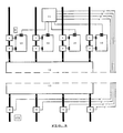
- FIG 3 shows a transmission system 12 having a plurality of hierarchically equivalent, but physically separated from one another, inputs (a,b,c,d).
- Each of the inputs is monitored by a monitoring device 10 such as was shown in the preceding figure.
- the external connections e1/e2 (indicated by "e1/2" in this figure) of the devices 10 come together in a transit unit 11.
- the function of said transit unit 11 is to make provision for the monitoring devices - which each control only the access to one physical input channel - to take account not only of the data cells which are presented to the system 12 via the physical channel they monitor but also of the data cells presented via the other physical channels in generating their evaluation signals and control signal (which actuate their switching unit 7).
- the transit unit ii plays a somewhat passive role and always transmits the external outgoing signals (e2) originating from the respective setting units 2 (not shown in this figure), of the various devices 10 to the other setting devices 2 (external incoming signals e1) so that account is taken of all the data cells presented via the various, physically separated input channels in the alteration units and/or evaluation units of all the monitoring devices 10. It is also possible for the transit unit 11 to play a more active role and even to totalise - on the basis of the outgoing external signals e2 - the number of data cells of the various input channels and to feed - via the ingoing external signal e1 - a correction signal to the other devices 10 on the basis thereof.
- Figure 4 shows an exemplary embodiment in which the transmission system 12 - as in Figure 3 - is monitored by means of a number of monitoring devices 10, each for one physical input channel (a,b,c,d), but in which the total number of data cells for each (potential) congestion point is not logged upstream of said congestion point (considered in the direction of the data flow), as in the preceding exemplary embodiments, but downstream of it.
- the exemplary embodiment shown in this figure comprises a number of detection units 8, viz. one per physical output (A,B,C,D) of the transmission system 12. In this case, each output (A,B,C,D) is considered to be connected to one potential congestion point.
- the detection units 8 it is, of course, also possible for, for example, two outputs to be connected to one and the same potential congestion point.
- the detection units 8 the number of data cells which is transmitted by the respective output channel is detected.
- the detection units 8 therefore fulfil a role which corresponds to that of the reading unit 1, but it is not necessary for the contents of the control words to be read out by the detection units 8.
- the count signal (u) generated by the detection units 8 therefore gives an indication of the number of data cells passing through the respective output; this may be the total number or, for example, the average number over a particular interval of time.
- the count signal (u) generated in this way is fed to the transit unit 11 which feeds the respective count signals originating from the detection units 8 to the first processing units 3a (shown in the preceding figures). Let each of the outputs A,B,C and D be a potential congestion point. The count signal (u) of, for example, output A will then be presented to the setting unit 2 (not shown) of each monitoring device via the transit unit 11.
- the setting device 2 then alters the variable belonging to the group of channels intended for output A (which variable therefore represents the number of data cells intended for output A) in the alteration unit 4a and subsequently evaluates it in the evaluation unit 5a.
- the count signals of the outputs B, C and D - also potential congestion points - are processed in the same way; the processing thereof in the monitoring devices 10 should, in fact, be carried out (preferably) in processing units 3 other than those already mentioned, for example processing units 3e, 3f and 3g, the position of which in the monitoring devices 10 can be deduced in an obvious manner.
- the number of data cells which is transmitted by those two outputs are combined by, for example, combining count signals (u) originating from the respective detection units 8 of the outputs B and C in the transit unit 11.
Landscapes
- Engineering & Computer Science (AREA)
- Computer Networks & Wireless Communication (AREA)
- Signal Processing (AREA)
- Data Exchanges In Wide-Area Networks (AREA)
- Time-Division Multiplex Systems (AREA)
- Communication Control (AREA)
- Maintenance And Management Of Digital Transmission (AREA)
Applications Claiming Priority (2)
| Application Number | Priority Date | Filing Date | Title |
|---|---|---|---|
| NL8902504A NL8902504A (nl) | 1989-10-09 | 1989-10-09 | Methode voor het bewaken van een transmissiesysteem dat een meervoud van virtuele, asynchroon tijdverdeelde transmissiekanalen omvat via welke een datastroom kan worden overgedragen. |
| NL8902504 | 1989-10-09 |
Publications (2)
| Publication Number | Publication Date |
|---|---|
| EP0422717A1 true EP0422717A1 (fr) | 1991-04-17 |
| EP0422717B1 EP0422717B1 (fr) | 1995-02-22 |
Family
ID=19855427
Family Applications (1)
| Application Number | Title | Priority Date | Filing Date |
|---|---|---|---|
| EP90202592A Expired - Lifetime EP0422717B1 (fr) | 1989-10-09 | 1990-10-01 | Méthode pour la surveillance d'un système de transmission comprenant une pluralité de canaux virtuels de transmission à repartition dans le temps asynchrone sur lequels un flux de données peut être transmis |
Country Status (9)
| Country | Link |
|---|---|
| US (1) | US5224091A (fr) |
| EP (1) | EP0422717B1 (fr) |
| JP (1) | JP2517468B2 (fr) |
| AT (1) | ATE118942T1 (fr) |
| CA (1) | CA2026872C (fr) |
| DE (1) | DE69017136T2 (fr) |
| DK (1) | DK0422717T3 (fr) |
| ES (1) | ES2069672T3 (fr) |
| NL (1) | NL8902504A (fr) |
Cited By (5)
| Publication number | Priority date | Publication date | Assignee | Title |
|---|---|---|---|---|
| EP0523386A1 (fr) * | 1991-06-18 | 1993-01-20 | Fujitsu Limited | Système de surveillance de normalité d'opération d'un appareil ATM d'interconnexion |
| FR2685837A1 (fr) * | 1991-12-30 | 1993-07-02 | Cit Alcatel | Dispositif de determination de l'histogramme de debit de circuits virtuels empruntant une voie de transmission a multiplexage temporel asynchrone. |
| WO1994014264A1 (fr) * | 1992-12-14 | 1994-06-23 | Nokia Telecommunications Oy | Procede de gestion de l'encombrement dans un reseau de transmission de trames, et noeud de reseau de transmission de trames |
| WO1994014263A1 (fr) * | 1992-12-14 | 1994-06-23 | Nokia Telecommunications Oy | Procede de gestion de l'encombrement dans un reseau de transmission de trames, et noeud de reseau de transmission de trames |
| EP0724794A4 (fr) * | 1993-10-20 | 1998-08-26 | Lsi Logic Corp | Appareil de detection et de correction d'erreurs pour dispositif de reseau a mode de transfert asynchrone |
Families Citing this family (8)
| Publication number | Priority date | Publication date | Assignee | Title |
|---|---|---|---|---|
| US5691975A (en) * | 1993-03-12 | 1997-11-25 | Fujitsu Limited | Method and apparatus for control in ATM |
| JP2870569B2 (ja) * | 1993-03-22 | 1999-03-17 | 富士通株式会社 | フレームリレー交換装置における輻輳処理方式および輻輳処理回路 |
| NL9301156A (nl) * | 1993-07-01 | 1995-02-01 | Nederland Ptt | ATM Celdetector. |
| US5457687A (en) * | 1993-09-02 | 1995-10-10 | Network Equipment Technologies, Inc. | Method and apparatus for backward explicit congestion notification (BECN) in an ATM network |
| JPH07183888A (ja) * | 1993-12-24 | 1995-07-21 | Fujitsu Ltd | Atm多重化制御方式 |
| JPH07264189A (ja) * | 1994-03-16 | 1995-10-13 | Fujitsu Ltd | プライベートatm網等におけるトラヒック制御装置 |
| NL9500585A (nl) * | 1995-03-27 | 1996-11-01 | Nederland Ptt | ATM policing orgaan. |
| US5878885A (en) * | 1997-10-14 | 1999-03-09 | Automated Healthcare, Inc. | Blister package with sloped raised formations |
Citations (1)
| Publication number | Priority date | Publication date | Assignee | Title |
|---|---|---|---|---|
| EP0275678A1 (fr) * | 1986-12-31 | 1988-07-27 | AT&T Corp. | Système de commutation de paquets avec contrôle de la congestion par gestion de largeur de bande |
Family Cites Families (7)
| Publication number | Priority date | Publication date | Assignee | Title |
|---|---|---|---|---|
| US4814979A (en) * | 1981-04-01 | 1989-03-21 | Teradata Corporation | Network to transmit prioritized subtask pockets to dedicated processors |
| JPH06105912B2 (ja) * | 1986-07-04 | 1994-12-21 | 日本電信電話株式会社 | パケツト呼処理方法 |
| US4769811A (en) * | 1986-12-31 | 1988-09-06 | American Telephone And Telegraph Company, At&T Bell Laboratories | Packet switching system arranged for congestion control |
| JPS6439845A (en) * | 1987-08-06 | 1989-02-10 | Mitsubishi Electric Corp | Data transmission equipment |
| JP2692104B2 (ja) * | 1988-02-12 | 1997-12-17 | 株式会社日立製作所 | 音声多重化システム |
| JPH01221042A (ja) * | 1988-02-29 | 1989-09-04 | Toshiba Corp | パケット交換機の輻輳制御方法 |
| US4979100A (en) * | 1988-04-01 | 1990-12-18 | Sprint International Communications Corp. | Communication processor for a packet-switched network |
-
1989
- 1989-10-09 NL NL8902504A patent/NL8902504A/nl not_active Application Discontinuation
-
1990
- 1990-10-01 ES ES90202592T patent/ES2069672T3/es not_active Expired - Lifetime
- 1990-10-01 EP EP90202592A patent/EP0422717B1/fr not_active Expired - Lifetime
- 1990-10-01 DK DK90202592.3T patent/DK0422717T3/da active
- 1990-10-01 DE DE69017136T patent/DE69017136T2/de not_active Expired - Lifetime
- 1990-10-01 AT AT90202592T patent/ATE118942T1/de not_active IP Right Cessation
- 1990-10-02 US US07/591,699 patent/US5224091A/en not_active Expired - Lifetime
- 1990-10-03 CA CA002026872A patent/CA2026872C/fr not_active Expired - Lifetime
- 1990-10-09 JP JP26969590A patent/JP2517468B2/ja not_active Expired - Lifetime
Patent Citations (1)
| Publication number | Priority date | Publication date | Assignee | Title |
|---|---|---|---|---|
| EP0275678A1 (fr) * | 1986-12-31 | 1988-07-27 | AT&T Corp. | Système de commutation de paquets avec contrôle de la congestion par gestion de largeur de bande |
Non-Patent Citations (1)
| Title |
|---|
| 1986 INTERNATIONAL ZURICH SEMINAR ON DIGITAL COMMUNICATION March 1986, IEEE Zürich CH pages 25 - 32; J.S.TURNER: "New Directions in Communications" * |
Cited By (8)
| Publication number | Priority date | Publication date | Assignee | Title |
|---|---|---|---|---|
| EP0523386A1 (fr) * | 1991-06-18 | 1993-01-20 | Fujitsu Limited | Système de surveillance de normalité d'opération d'un appareil ATM d'interconnexion |
| US5280469A (en) * | 1991-06-18 | 1994-01-18 | Fujitsu Limited | System for monitoring normality of operation of ATM cross-connecting apparatus |
| FR2685837A1 (fr) * | 1991-12-30 | 1993-07-02 | Cit Alcatel | Dispositif de determination de l'histogramme de debit de circuits virtuels empruntant une voie de transmission a multiplexage temporel asynchrone. |
| EP0550328A1 (fr) * | 1991-12-30 | 1993-07-07 | Alcatel Cit | Dispositif et procédé de détermination de l'histogramme de débit de circuits virtuels |
| WO1994014264A1 (fr) * | 1992-12-14 | 1994-06-23 | Nokia Telecommunications Oy | Procede de gestion de l'encombrement dans un reseau de transmission de trames, et noeud de reseau de transmission de trames |
| WO1994014263A1 (fr) * | 1992-12-14 | 1994-06-23 | Nokia Telecommunications Oy | Procede de gestion de l'encombrement dans un reseau de transmission de trames, et noeud de reseau de transmission de trames |
| US5638359A (en) * | 1992-12-14 | 1997-06-10 | Nokia Telecommunications Oy | Method for congestion management in a frame relay network and a node in a frame relay network |
| EP0724794A4 (fr) * | 1993-10-20 | 1998-08-26 | Lsi Logic Corp | Appareil de detection et de correction d'erreurs pour dispositif de reseau a mode de transfert asynchrone |
Also Published As
| Publication number | Publication date |
|---|---|
| JP2517468B2 (ja) | 1996-07-24 |
| ES2069672T3 (es) | 1995-05-16 |
| JPH03145243A (ja) | 1991-06-20 |
| US5224091A (en) | 1993-06-29 |
| EP0422717B1 (fr) | 1995-02-22 |
| ATE118942T1 (de) | 1995-03-15 |
| DE69017136T2 (de) | 1995-08-03 |
| DK0422717T3 (da) | 1995-07-10 |
| NL8902504A (nl) | 1991-05-01 |
| CA2026872A1 (fr) | 1991-04-10 |
| CA2026872C (fr) | 1994-05-24 |
| DE69017136D1 (de) | 1995-03-30 |
Similar Documents
| Publication | Publication Date | Title |
|---|---|---|
| US5774453A (en) | Input/output buffer type ATM switch | |
| EP0422717B1 (fr) | Méthode pour la surveillance d'un système de transmission comprenant une pluralité de canaux virtuels de transmission à repartition dans le temps asynchrone sur lequels un flux de données peut être transmis | |
| US5978359A (en) | Allocated and dynamic switch flow control | |
| US5671215A (en) | Method and circuit arrangement for transmitting message cells via redundant, virtual path pairs of an ATM communication network | |
| EP0907300A2 (fr) | ContrÔleur de tampon incorporé dans un réseau ATM pour la modification de débit de cellules dépendant de la durée de congestion | |
| US5282203A (en) | Method of and system for controlling packet-rate in communication network | |
| US5719865A (en) | Traffic shaping method and apparatus for ATM switching unit | |
| Bonde et al. | A comparative study of fuzzy versus" fixed" thresholds for robust queue management in cell-switching networks | |
| US5280483A (en) | Traffic control system for asynchronous transfer mode exchange | |
| JP3115546B2 (ja) | Atmセルを最適に伝送する方法 | |
| US5313455A (en) | Transmission system with recording of untransmitted packets | |
| EP0669737A2 (fr) | Routage intrabande dans un réseau de données | |
| AU6981198A (en) | An input buffer controller using back-pressure signals in ATM switches and a method for determining the logical queue depth | |
| JPH07154424A (ja) | デ−タパケットを一時的に記憶する方法および装置とこのような装置を有する交換装置 | |
| EP0508378B1 (fr) | Méthode et système pour la surveillance de débit de paquets dans un réseau de paquets | |
| US5283782A (en) | System switching method and apparatus without loss of signal in cell switching system of asynchronous transfer mode | |
| EP0366635B1 (fr) | Méthode et dispositif pour prévenir la transmission de paquets de données avec une intensité plus grande qu'une valeur prédéterminée dans chacun d'un nombre de canaux d'une ligne de transmission commune | |
| US5787073A (en) | ATM cell rate control with transmission priority given to control cells for quick response to network congestion | |
| CA2235135A1 (fr) | Ameliorations concernant un commutateur mta | |
| US6122253A (en) | ATM network switch with congestion control | |
| CA2162211A1 (fr) | Installation double pour systeme de commutation mta | |
| US6002666A (en) | Traffic shaping apparatus with content addressable memory | |
| US6266338B1 (en) | System for the regulation of information trains for packets | |
| US5138612A (en) | Time-division multiplex transmission system | |
| US6181701B1 (en) | Method for optimizing the transmission of ATM cells via connection sections |
Legal Events
| Date | Code | Title | Description |
|---|---|---|---|
| PUAI | Public reference made under article 153(3) epc to a published international application that has entered the european phase |
Free format text: ORIGINAL CODE: 0009012 |
|
| 17P | Request for examination filed |
Effective date: 19901218 |
|
| AK | Designated contracting states |
Kind code of ref document: A1 Designated state(s): AT BE CH DE DK ES FR GB GR IT LI LU NL SE |
|
| 17Q | First examination report despatched |
Effective date: 19940407 |
|
| GRAA | (expected) grant |
Free format text: ORIGINAL CODE: 0009210 |
|
| AK | Designated contracting states |
Kind code of ref document: B1 Designated state(s): AT BE CH DE DK ES FR GB GR IT LI LU NL SE |
|
| REF | Corresponds to: |
Ref document number: 118942 Country of ref document: AT Date of ref document: 19950315 Kind code of ref document: T |
|
| REF | Corresponds to: |
Ref document number: 69017136 Country of ref document: DE Date of ref document: 19950330 |
|
| ITF | It: translation for a ep patent filed | ||
| REG | Reference to a national code |
Ref country code: ES Ref legal event code: FG2A Ref document number: 2069672 Country of ref document: ES Kind code of ref document: T3 |
|
| ET | Fr: translation filed | ||
| REG | Reference to a national code |
Ref country code: DK Ref legal event code: T3 |
|
| REG | Reference to a national code |
Ref country code: GR Ref legal event code: FG4A Free format text: 3016192 |
|
| PLBE | No opposition filed within time limit |
Free format text: ORIGINAL CODE: 0009261 |
|
| STAA | Information on the status of an ep patent application or granted ep patent |
Free format text: STATUS: NO OPPOSITION FILED WITHIN TIME LIMIT |
|
| 26N | No opposition filed | ||
| REG | Reference to a national code |
Ref country code: CH Ref legal event code: PFA Free format text: KONINKLIJKE PTT NEDERLAND N.V. TRANSFER- KONINKLIJKE KPN N.V. |
|
| REG | Reference to a national code |
Ref country code: GB Ref legal event code: IF02 |
|
| PGFP | Annual fee paid to national office [announced via postgrant information from national office to epo] |
Ref country code: LU Payment date: 20041011 Year of fee payment: 15 |
|
| PGFP | Annual fee paid to national office [announced via postgrant information from national office to epo] |
Ref country code: GR Payment date: 20041027 Year of fee payment: 15 |
|
| PG25 | Lapsed in a contracting state [announced via postgrant information from national office to epo] |
Ref country code: LU Free format text: LAPSE BECAUSE OF NON-PAYMENT OF DUE FEES Effective date: 20051031 |
|
| REG | Reference to a national code |
Ref country code: CH Ref legal event code: PCAR Free format text: ISLER & PEDRAZZINI AG;POSTFACH 1772;8027 ZUERICH (CH) |
|
| PG25 | Lapsed in a contracting state [announced via postgrant information from national office to epo] |
Ref country code: GR Free format text: LAPSE BECAUSE OF NON-PAYMENT OF DUE FEES Effective date: 19950222 |
|
| PGFP | Annual fee paid to national office [announced via postgrant information from national office to epo] |
Ref country code: ES Payment date: 20091023 Year of fee payment: 20 Ref country code: DK Payment date: 20091014 Year of fee payment: 20 Ref country code: DE Payment date: 20091026 Year of fee payment: 20 Ref country code: CH Payment date: 20091026 Year of fee payment: 20 Ref country code: AT Payment date: 20091015 Year of fee payment: 20 Ref country code: SE Payment date: 20091014 Year of fee payment: 20 |
|
| PGFP | Annual fee paid to national office [announced via postgrant information from national office to epo] |
Ref country code: NL Payment date: 20091016 Year of fee payment: 20 |
|
| PGFP | Annual fee paid to national office [announced via postgrant information from national office to epo] |
Ref country code: GB Payment date: 20091022 Year of fee payment: 20 Ref country code: FR Payment date: 20091110 Year of fee payment: 20 Ref country code: IT Payment date: 20091028 Year of fee payment: 20 |
|
| PGFP | Annual fee paid to national office [announced via postgrant information from national office to epo] |
Ref country code: BE Payment date: 20091130 Year of fee payment: 20 |
|
| REG | Reference to a national code |
Ref country code: NL Ref legal event code: V4 Effective date: 20101001 |
|
| REG | Reference to a national code |
Ref country code: CH Ref legal event code: PL |
|
| REG | Reference to a national code |
Ref country code: DK Ref legal event code: EUP |
|
| REG | Reference to a national code |
Ref country code: GB Ref legal event code: PE20 Expiry date: 20100930 |
|
| BE20 | Be: patent expired |
Owner name: KONINKLIJKE *PTT NEDERLAND N.V. Effective date: 20101001 |
|
| EUG | Se: european patent has lapsed | ||
| PG25 | Lapsed in a contracting state [announced via postgrant information from national office to epo] |
Ref country code: GB Free format text: LAPSE BECAUSE OF EXPIRATION OF PROTECTION Effective date: 20100930 |
|
| PG25 | Lapsed in a contracting state [announced via postgrant information from national office to epo] |
Ref country code: NL Free format text: LAPSE BECAUSE OF EXPIRATION OF PROTECTION Effective date: 20101001 |
|
| REG | Reference to a national code |
Ref country code: ES Ref legal event code: FD2A Effective date: 20120509 |
|
| PG25 | Lapsed in a contracting state [announced via postgrant information from national office to epo] |
Ref country code: ES Free format text: LAPSE BECAUSE OF EXPIRATION OF PROTECTION Effective date: 20101002 |
|
| PG25 | Lapsed in a contracting state [announced via postgrant information from national office to epo] |
Ref country code: DE Free format text: LAPSE BECAUSE OF EXPIRATION OF PROTECTION Effective date: 20101001 |