EP0422738B1 - Appareil pour la distribution de quantités d'eau de température variable - Google Patents
Appareil pour la distribution de quantités d'eau de température variable Download PDFInfo
- Publication number
- EP0422738B1 EP0422738B1 EP90202679A EP90202679A EP0422738B1 EP 0422738 B1 EP0422738 B1 EP 0422738B1 EP 90202679 A EP90202679 A EP 90202679A EP 90202679 A EP90202679 A EP 90202679A EP 0422738 B1 EP0422738 B1 EP 0422738B1
- Authority
- EP
- European Patent Office
- Prior art keywords
- water
- reservoir
- boiling point
- atmospheric boiling
- outlet
- Prior art date
- Legal status (The legal status is an assumption and is not a legal conclusion. Google has not performed a legal analysis and makes no representation as to the accuracy of the status listed.)
- Expired - Lifetime
Links
- XLYOFNOQVPJJNP-UHFFFAOYSA-N water Substances O XLYOFNOQVPJJNP-UHFFFAOYSA-N 0.000 title claims abstract description 136
- 238000009835 boiling Methods 0.000 claims abstract description 72
- 238000010438 heat treatment Methods 0.000 claims abstract description 10
- 238000011144 upstream manufacturing Methods 0.000 claims description 7
- OKTJSMMVPCPJKN-UHFFFAOYSA-N Carbon Chemical compound [C] OKTJSMMVPCPJKN-UHFFFAOYSA-N 0.000 claims description 2
- 229910052799 carbon Inorganic materials 0.000 claims description 2
- 238000009413 insulation Methods 0.000 description 2
- 239000008399 tap water Substances 0.000 description 2
- 235000020679 tap water Nutrition 0.000 description 2
- 241001122767 Theaceae Species 0.000 description 1
- 230000002411 adverse Effects 0.000 description 1
- 230000005540 biological transmission Effects 0.000 description 1
- 238000010276 construction Methods 0.000 description 1
- 238000010411 cooking Methods 0.000 description 1
- 230000007797 corrosion Effects 0.000 description 1
- 238000005260 corrosion Methods 0.000 description 1
- 230000006866 deterioration Effects 0.000 description 1
- 238000004851 dishwashing Methods 0.000 description 1
- 230000000694 effects Effects 0.000 description 1
- 230000007794 irritation Effects 0.000 description 1
- 235000012054 meals Nutrition 0.000 description 1
- 238000004904 shortening Methods 0.000 description 1
- 238000005406 washing Methods 0.000 description 1
- 239000002699 waste material Substances 0.000 description 1
Images
Classifications
-
- F—MECHANICAL ENGINEERING; LIGHTING; HEATING; WEAPONS; BLASTING
- F24—HEATING; RANGES; VENTILATING
- F24D—DOMESTIC- OR SPACE-HEATING SYSTEMS, e.g. CENTRAL HEATING SYSTEMS; DOMESTIC HOT-WATER SUPPLY SYSTEMS; ELEMENTS OR COMPONENTS THEREFOR
- F24D19/00—Details
- F24D19/10—Arrangement or mounting of control or safety devices
- F24D19/1006—Arrangement or mounting of control or safety devices for water heating systems
- F24D19/1051—Arrangement or mounting of control or safety devices for water heating systems for domestic hot water
-
- A—HUMAN NECESSITIES
- A47—FURNITURE; DOMESTIC ARTICLES OR APPLIANCES; COFFEE MILLS; SPICE MILLS; SUCTION CLEANERS IN GENERAL
- A47J—KITCHEN EQUIPMENT; COFFEE MILLS; SPICE MILLS; APPARATUS FOR MAKING BEVERAGES
- A47J31/00—Apparatus for making beverages
- A47J31/44—Parts or details or accessories of beverage-making apparatus
- A47J31/54—Water boiling vessels in beverage making machines
- A47J31/56—Water boiling vessels in beverage making machines having water-level controls; having temperature controls
-
- E—FIXED CONSTRUCTIONS
- E03—WATER SUPPLY; SEWERAGE
- E03C—DOMESTIC PLUMBING INSTALLATIONS FOR FRESH WATER OR WASTE WATER; SINKS
- E03C1/00—Domestic plumbing installations for fresh water or waste water; Sinks
- E03C1/02—Plumbing installations for fresh water
- E03C1/04—Water-basin installations specially adapted to wash-basins or baths
- E03C1/0411—Taps specially designed for dispensing boiling water
Definitions
- This invention relates to an apparatus for dispensing - in particular - small quantities of boiling water and water of variable temperatures below its atmospheric boiling point, comprising a reservoir directly connected to the mains for heating and storing water at a temperature above its atmospheric boiling point, and an outlet for boiling water, the reservoir being fully filled with water during normal operating conditions.
- an apparatus as defined in the opening paragraph which is capable of meeting greatly varying requirements of instant boiling water, with a relatively short residence time of water in the reservoir, which is heated above its atmospheric boiling point, so as to avoid the drawback of deterioration in taste qualities of the water.
- the apparatus has at least one outlet connected to a source of water having a temperature lower than the atmospheric boiling point.
- the invention relates to an apparatus for dispensing boiling water and water of variable temperatures below its atmospheric boiling point, comprising a reservoir directly connected to the mains, and heating means and a thermostat for heating and storing water at a temperature above its atmospheric boiling point, which connection terminates in the bottom part of the reservoir at means which horizontally deflect the incoming water, which reservoir is fully filled with water under normal operating conditions and has a connection at its upperside for one outlet for dispensing boiling water and at least one outlet connected to a source of water having a temperature lower than its atmospheric boiling point through a mixing device including valves allowing the dispensing of water of variable lower temperatures by mixing in any desired ratio the water having a temperature lower than its atmospheric boiling point and water heated above its atmospheric boiling point.
- the water heated above its atmospheric boiling point is also used for providing hot water, for example, for dishwashing or for washing the hands.
- hot water for example, for dishwashing or for washing the hands.
- the apparatus according to this aspect of the invention is characterized in that the reservoir in which water is heated and stored at a temperature above its atmospheric boiling point is connected to an outlet for both boiling water and hot water of a lower temperature through a mixing device to which a source of water having a temperature lower than its atmospheric boiling point is connected.
- the apparatus according to this invention may in principle comprise a reservoir section in which water is heated and stored at a temperature above its atmospheric boiling point with a connection to the water mains which terminates in the bottom part of the reservoir, and permitting the ingress of cold water as well as possible in the horizontal direction, and outlet means connected to the top of the reservoir, not only for dispensing boiling water, but also for hot water which is obtained by using means for admixing colder water on its way to the outlet opening.
- the water to be mixed upstream of the outlet opening will be tap water.
- the reservoir comprises two sections arranged in series, the mains being connected to the bottom of the reservoir section in which water is heated and stored at a temperature below its atmospheric boiling point.
- the top of this first reservoir section is connected to the second reservoir section, in which water is heated and stored at a temperature above its atmospheric boiling point, and to the top of which an outlet for boiling water is connected.
- the source of water having a temperature lower than its atmospheric boiling point is the water mains and/or the reservoir section in which water is stored at said lower temperature.
- the reservoir for water having a temperature above its atmospheric boiling point may be smaller than that in the embodiment described before, as a consequence of which the average residence time of the water in said reservoir is shortened.
- the apparatus according to this invention also offers advantages over and above existing, separate devices in terms of heat economy.
- British patent application 2,079,908 relates to an apparatus for dispensing steam, boiling and non-boiling water. Apart from its complex construction, that apparatus is not fully filled with water during normal operating conditions, in view of the necessary presence of a level regulation. As a consequence, water is expelled under varying vapour pressure. In addition, air collects in the top of the device, which gives rise to problems of corrosion. In the apparatus described in German patent specification 625857, too, boiling water is expelled under vapour pressure. The apparatus is provided with a float to ensure sufficient vapour space in the apparatus.
- United States patent specification 4,575,615 relates to an apparatus consisting of two compartments interconnected by means of a screen plate. Water having a temperature of approximately 85°C can be drawn off from the lower part. The water in the top part is maintained at a higher temperature than is the water in the bottom part. The water having a temperature just below 100°C is provided by passing water from the bottom part of the apparatus through a heat exchanger arranged in its top part.
- European patent application 0 307 955 relates to a coffee making machine, from which wet steam and hot water, i.e. non-boiling water, can be drawn off.
- the machine is provided with a pump which provides the driving force when water is dispensed.
- This machine has one outlet for hot water without the possibility of controlling its temperature.
- both can provide boiling water and are equipped with a reservoir in which tap water is heated and maintained at a temperature above its atmospheric boiling point, and both can also dispense hot water having a temperature below its atmospheric boiling point.
- the entire reservoir contents are heated and maintained at a temperature above its atmospheric boiling point
- the first embodiment is less expensive to make than the second, but the second is preferred when, from the point of view of safety, the volume of the reservoir for water having a temperature above its atmospheric boiling point must be limited.
- heat losses are less than in the first group, especially when the reservoir section which is at the higher temperature is provided fully or partially within the reservoir section for water at the lower temperature.
- the thermal insulation between the reservoir section at the higher temperature and the reservoir section at the lower temperature serves to ensure that heat transmission between the two is less than thermal losses to the outside of the reservoir section at the lower temperature.
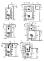
- a reservoir 1 is connected at the bottom to the water mains 2, which connection terminates at means 3 which horizontally deflect the incoming water.
- a heating element 4 is shown, which, controlled by a thermostat 5, heats the reservoir contents at a temperature above its atmospheric boiling point, e.g., 110°C, and maintains this temperature.
- the reservoir 1 is surrounded by an insulating jacket 6.
- the top of reservoir 1 is connected to an outlet line which, through a boiling-water valve 7, is connected to an outlet opening 10 for hot or boiling water.
- valve 7 Connected to valve 7 is a cold-water pipeline with a cold-water valve 9.
- cold water and water heated above its atmospheric boiling point can be mixed in any desired ratio before leaving the outlet opening 10.
- the apparatus illustrated in Fig. 2 is distinguished from that shown in Fig. 1 in that, in addition to the outlet line with the boiling-water valve 7, a separate outlet line with a boiling-water valve 11 and an outlet 12 is provided.
- the outlet lines have separate connections 13 and 14 in the top part of reservoir 1.
- a carbon filter 15 may be mounted upstream of connection 13.
- Fig. 3 differs from that shown in Fig. 2 in that, through a by-pass branching off upstream of the cold-water valve 9, cold water can be supplied to a point upstream of the boiling-water valve 7. In this way, no boiling water, but water having a lower temperature, e.g., 80°C, is supplied to valve 7. This temperature can be adjusted by throttle means 16 and 17 in the outlet lines concerned. If desired, throttle means 17 may be provided with a non-return valve.
- throttle means 16 and/or 17 may be provided in the insulating jacket 6.
- Fig. 4 illustrates an example of a reservoir consisting of two sections.
- the water mains 2 is connected to the bottom part of the first, bottom reservoir section 18, in which the water is heated and maintained at a temperature below its atmospheric boiling point, e.g., 80°C.
- the top of the first reservoir section 18 is in connection with the bottom part of the second reservoir section 19, whose contents can be heated and maintained at a temperature above the atmospheric boiling point by means of its own heating element 21 and a thermostat 20.
- the boiling-water valve 11 boiling water can be dispensed.
- the second reservoir section 19 is provided with a second outlet, which is in communication, through throttle means 17, with the boiling-water valve 7.
- a by-pass branching off upstream of the cold-water valve 9 cold water can be supplied to a point upstream of the boiling-water valve 7.
- water having a lower temperature e.g. 80°C.
- This temperature can be adjusted with the help of throttle means 16 and 17 in the outlet lines concerned.
- This embodiment offers the additional advantage of an intensive throughflow in reservoir 19.
- the two reservoir sections 18 and 19 can naturally be arranged in separate insulating jackets, spaced apart some distance from each other.
- the quantity of hot water and its temperature can be selected to suit requirements by means of the valve 7, which is in communication with the top part of the first reservoir 18 and with valve 9 in the water conduit 2.
- the boiling-water section may alternatively be arranged fully or partially within the hot-water section.
- the dimensions of the several reservoirs are not critical and may vary within wide ranges.
- the volume of the boiling-water reservoir in the embodiment of Figs. 1-3 is, for example, up to 12 liters, more specifically 6-10 liters.
- the boiling-water reservoir in the embodiment of Figs. 4-5 may be smaller, for example, up to 7 liters, and more particularly 1-5 liters.
- the volume of the reservoir for water of lower temperature according to Figs. 4-5 will be mainly determined by dimensional considerations.
- a suitable volume of this reservoir is maximally 15 liters, particularly 8-12 liters.
Landscapes
- Engineering & Computer Science (AREA)
- Combustion & Propulsion (AREA)
- General Engineering & Computer Science (AREA)
- Hydrology & Water Resources (AREA)
- Public Health (AREA)
- Water Supply & Treatment (AREA)
- Food Science & Technology (AREA)
- Physics & Mathematics (AREA)
- Thermal Sciences (AREA)
- Chemical & Material Sciences (AREA)
- Health & Medical Sciences (AREA)
- Life Sciences & Earth Sciences (AREA)
- Mechanical Engineering (AREA)
- Apparatus For Making Beverages (AREA)
- Heat-Pump Type And Storage Water Heaters (AREA)
- Temperature-Responsive Valves (AREA)
- Devices For Dispensing Beverages (AREA)
- Domestic Hot-Water Supply Systems And Details Of Heating Systems (AREA)
- Water Treatment By Sorption (AREA)
- Sampling And Sample Adjustment (AREA)
- Domestic Plumbing Installations (AREA)
- Feeding, Discharge, Calcimining, Fusing, And Gas-Generation Devices (AREA)
- Cookers (AREA)
Claims (7)
- Dispositif pour distribuer de l'eau bouillante et de l'eau de température variable inférieure à son point d'ébullition atmosphérique, comprenant un réservoir (1) raccordé directement au réseau d'adduction d'eau (2), et des moyens de chauffage (4) et un thermostat (5) pour chauffer et stocker l'eau à une température supérieure à son point d'ébullition atmosphérique, raccordement qui se termine dans la partie de fond du réservoir au niveau de moyens (3) qui dévient horizontalement l'eau entrante, réservoir qui est entièrement rempli d'eau dans les conditions normales de fonctionnement et comporte un raccordement au niveau de sa partie supérieure pour une sortie (10, 12) destinée à distribuer de l'eau bouillante et au moins une sortie (10) reliée à une source d'eau (2, 18) ayant une température inférieure à son point d'ébullition atmosphérique par l'intermédiaire d'un dispositif de mélange (7, 9, 17, 16) comprenant des vannes (7, 9), permettant la distribution d'eau à diverses températures inférieures en mélangeant en toute proportion désirée quelconque l'eau ayant une température inférieure à son point d'ébullition atmosphérique et de l'eau chauffée au-dessus de son point d'ébullition atmosphérique.
- Dispositif selon la revendication 1, dans lequel le réservoir (1) comprend deux parties (18, 19) disposées en série, le réseau d'adduction d'eau (2) étant raccordé à la partie inférieure de la première partie de réservoir (18) dans laquelle l'eau est chauffée et stockée à une température inférieure à son point d'ébullition atmosphérique, et la partie supérieure de ladite première partie de réservoir (18) étant reliée à la seconde partie de réservoir (19) dans laquelle l'eau est chauffée et stockée à une température supérieure au point d'ébullition atmosphérique, et au sommet de laquelle est raccordée une sortie (12) pour l'eau bouillante.
- Dispositif selon la revendication 1 ou la revendication 2, dans lequel la source d'eau ayant une température inférieure à son point d'ébullition atmosphérique est le réseau d'adduction d'eau (2) et/ou la première partie de réservoir (18) dans laquelle l'eau est chauffée à une température inférieure à son point d'ébullition atmosphérique.
- Dispositif selon la revendication 2, dans lequel la seconde partie de réservoir (19) est disposée en partie à l'intérieur de ladite première partie de réservoir (18).
- Dispositif selon la revendication 3 ou 4, dans lequel les vannes (7, 9) sont respectivement prévues dans la conduite d'eau bouillante et dans la conduite d'eau chaude ou froide, et auquel sont adjoints en option des moyens de vannes d'étranglement (17, 16) dans lesdites conduites.
- Dispositif selon l'une quelconque des revendications précédentes, dans lequel un filtre au carbone (15) est disposé en amont du raccordement (13) de la conduite de sortie d'eau ayant une température supérieure au point d'ébullition atmosphérique.
- Dispositif selon l'une quelconque des revendications précédentes, dans lequel la sortie destinée à la distribution d'eau bouillante et la sortie raccordée à la source d'eau ayant une température inférieure à son point d'ébullition atmosphérique ne font qu'une.
Applications Claiming Priority (2)
| Application Number | Priority Date | Filing Date | Title |
|---|---|---|---|
| NL8902513 | 1989-10-10 | ||
| NL8902513A NL8902513A (nl) | 1989-10-10 | 1989-10-10 | Inrichting voor het leveren van hoeveelheden water met variabele temperaturen. |
Publications (2)
| Publication Number | Publication Date |
|---|---|
| EP0422738A1 EP0422738A1 (fr) | 1991-04-17 |
| EP0422738B1 true EP0422738B1 (fr) | 1995-07-05 |
Family
ID=19855432
Family Applications (1)
| Application Number | Title | Priority Date | Filing Date |
|---|---|---|---|
| EP90202679A Expired - Lifetime EP0422738B1 (fr) | 1989-10-10 | 1990-10-09 | Appareil pour la distribution de quantités d'eau de température variable |
Country Status (10)
| Country | Link |
|---|---|
| US (1) | US5093897A (fr) |
| EP (1) | EP0422738B1 (fr) |
| JP (1) | JP3157150B2 (fr) |
| AT (1) | ATE124781T1 (fr) |
| AU (1) | AU637832B2 (fr) |
| CA (1) | CA2027217C (fr) |
| DE (1) | DE69020679T2 (fr) |
| DK (1) | DK0422738T3 (fr) |
| ES (1) | ES2077018T3 (fr) |
| NL (1) | NL8902513A (fr) |
Families Citing this family (14)
| Publication number | Priority date | Publication date | Assignee | Title |
|---|---|---|---|---|
| WO1992012389A1 (fr) * | 1990-12-27 | 1992-07-23 | Thevenon Andre | Dispositif de production d'eau chaude sanitaire ou de chauffage |
| FR2679631B1 (fr) * | 1991-07-22 | 1994-02-18 | Andre Thevenon | Dispositif de production d'eau chaude sanitaire a thermosiphon integre. |
| WO1994008183A1 (fr) * | 1992-10-07 | 1994-04-14 | R. Edmonds & Sons Pty Ltd | Chauffe-eau produisant de l'eau chaude et bouillante |
| FR2703494B1 (fr) * | 1993-03-29 | 1995-08-04 | Distr Automatiques Lavall Cent | Distributeur de boissons chaudes. |
| US7401545B2 (en) * | 2004-11-09 | 2008-07-22 | Nestec S.A. | Method and apparatus for optimizing variable liquid temperatures |
| NL1032610C2 (nl) * | 2006-10-03 | 2008-04-04 | Henri Peteri Beheer Bv | Inrichting voor het afgeven van water met variabele temperaturen. |
| DE102008006255B4 (de) | 2008-01-25 | 2013-09-19 | Grohe Ag | Vorrichtung zur Abgabe von Wasser |
| US9268342B2 (en) * | 2011-06-15 | 2016-02-23 | General Electric Company | Water heater with integral thermal mixing valve assembly and method |
| ITTO20120726A1 (it) * | 2012-08-13 | 2014-02-14 | N&W Global Vending Spa | Caldaia ad accumulo |
| DE102016113834A1 (de) * | 2016-07-27 | 2018-02-01 | Blanco Gmbh + Co Kg | Armatur und Verfahren zum Bereitstellen von Mischwasser an einer Armatur |
| CN106510461B (zh) * | 2016-11-07 | 2018-11-13 | 四会市恒星智能科技有限公司 | 一种冷热即饮型净水饮水机 |
| EP3376119A1 (fr) * | 2017-03-13 | 2018-09-19 | Kendrion Kuhnke Automotive GmbH | Système d'alimentation d'une robinetterie d'amenée à régulation et procédé de remplissage du système |
| CN109000358B (zh) * | 2018-06-22 | 2020-11-27 | 王麒麟 | 一种自来水加热设备 |
| IT202100018644A1 (it) | 2021-07-14 | 2023-01-14 | Gruppo Cimbali Spa | Macchina per bevande ad infusione |
Family Cites Families (21)
| Publication number | Priority date | Publication date | Assignee | Title |
|---|---|---|---|---|
| DE625857C (de) * | 1934-08-02 | 1936-02-17 | Walter Becker Dipl Ing | Heisswassererzeuger fuer Aufbruehzwecke |
| US2515974A (en) * | 1944-10-28 | 1950-07-18 | Sarpsborg Elek Se Fabrikker | Overflow hot-water tank, preferably with electric heating, for a plurality of tapping places, without floating valve cistern |
| US2422492A (en) * | 1944-12-15 | 1947-06-17 | Losee Products Co | Displacement-type electric water heater |
| US2530382A (en) * | 1948-05-05 | 1950-11-21 | Downs Orville | Heating water by electricity |
| GB867670A (en) * | 1958-03-18 | 1961-05-10 | Bemar Societa A Garanzia Limit | Coffee-machine |
| US3254839A (en) * | 1963-07-05 | 1966-06-07 | Ace Tank And Heater Company | Unitary heating system |
| US3212566A (en) * | 1964-03-13 | 1965-10-19 | Worthington Corp | Service water sterilization system |
| US3351130A (en) * | 1965-12-22 | 1967-11-07 | Patterson Kelley Co | Dual temperature water heating and supply system |
| BE788523A (nl) * | 1971-09-08 | 1973-03-07 | Peteri Henri B | Heet-waterapparaat |
| DE2323744C3 (de) * | 1972-05-13 | 1978-11-23 | J. Uriach & Cia., S.A., Barcelona (Spanien) | 4,4'-Bismethylen-(3-methoxy-2-naphthoesäure-triamcinolon-acetonidester) und Verfahren zu dessen Herstellung |
| DE2434336C2 (de) * | 1974-07-17 | 1982-07-29 | Patzner KG Fabrik für Maschinen und elektrische Apparate, 6990 Bad Mergentheim | Kaffeemaschine |
| US3992607A (en) * | 1975-04-25 | 1976-11-16 | Jolin Jacques R | Electrically heated hot water system |
| DE2745959C3 (de) * | 1977-10-12 | 1985-01-24 | Württembergische Metallwarenfabrik, 7340 Geislingen | Kaffeemaschine |
| US4263498A (en) * | 1979-02-26 | 1981-04-21 | Hobart Corporation | Expansion chamber arrangement for water heating and dispensing device |
| DE3014493A1 (de) * | 1980-04-16 | 1981-10-22 | Emide-Metallindustrie Gebr. Streicher, 7209 Denkingen | Haushaltsgeraet mit heisswasserbereiter |
| GB2079908B (en) * | 1980-06-23 | 1984-05-16 | Metal Spinners Ireland Ltd | Steam and water boiler |
| US4354094A (en) * | 1980-11-12 | 1982-10-12 | Zip Heaters (Aust.) Pty. Limited | Thermostatically controlled electric continuous water heating unit |
| GB8331633D0 (en) * | 1983-11-26 | 1984-01-04 | Calomax Engineers Ltd | Water boilers |
| US4575615A (en) * | 1984-05-29 | 1986-03-11 | Toshiba Electric Appliances Co., Ltd. | Hot water supplying device |
| GB2176882B (en) * | 1985-06-28 | 1989-03-22 | Tzyy Der Shieh | Apparatus for supplying boiled water |
| IT1213904B (it) * | 1987-09-21 | 1990-01-05 | Alberto Rolla | Metodo per la regolazione della temperatura nelle macchine da caffe provviste di caldaia e macchina da caffe per l attuazione di tale metodo |
-
1989
- 1989-10-10 NL NL8902513A patent/NL8902513A/nl not_active Application Discontinuation
-
1990
- 1990-10-09 AU AU63934/90A patent/AU637832B2/en not_active Ceased
- 1990-10-09 AT AT90202679T patent/ATE124781T1/de not_active IP Right Cessation
- 1990-10-09 DE DE69020679T patent/DE69020679T2/de not_active Expired - Lifetime
- 1990-10-09 US US07/594,746 patent/US5093897A/en not_active Expired - Lifetime
- 1990-10-09 DK DK90202679.8T patent/DK0422738T3/da active
- 1990-10-09 ES ES90202679T patent/ES2077018T3/es not_active Expired - Lifetime
- 1990-10-09 EP EP90202679A patent/EP0422738B1/fr not_active Expired - Lifetime
- 1990-10-10 CA CA002027217A patent/CA2027217C/fr not_active Expired - Fee Related
- 1990-10-11 JP JP27314490A patent/JP3157150B2/ja not_active Expired - Fee Related
Also Published As
| Publication number | Publication date |
|---|---|
| AU6393490A (en) | 1991-04-18 |
| DK0422738T3 (da) | 1995-11-20 |
| JP3157150B2 (ja) | 2001-04-16 |
| CA2027217C (fr) | 2000-03-28 |
| AU637832B2 (en) | 1993-06-10 |
| JPH03194329A (ja) | 1991-08-26 |
| EP0422738A1 (fr) | 1991-04-17 |
| DE69020679T2 (de) | 1996-04-04 |
| CA2027217A1 (fr) | 1991-04-11 |
| US5093897A (en) | 1992-03-03 |
| NL8902513A (nl) | 1991-05-01 |
| DE69020679D1 (de) | 1995-08-10 |
| ATE124781T1 (de) | 1995-07-15 |
| ES2077018T3 (es) | 1995-11-16 |
Similar Documents
| Publication | Publication Date | Title |
|---|---|---|
| EP0422738B1 (fr) | Appareil pour la distribution de quantités d'eau de température variable | |
| US4341263A (en) | Waste water heat recovery apparatus | |
| JP2012511131A (ja) | 湯沸しシステム及びその作動方法 | |
| EP0467480B1 (fr) | Appareil pour la fourniture d'eau bouillante | |
| CN113830950A (zh) | 净水器 | |
| EP0635682A1 (fr) | Chaudière-mixte à accumulation de chaleur | |
| EP4119014B1 (fr) | Appareil de chauffage et de distribution d'eau | |
| CN216020516U (zh) | 饮水机及多档调温控制水路系统 | |
| US4197446A (en) | Energy-saving device for domestic water heaters | |
| CN101280933A (zh) | 不同种类热水器的联合使用方法 | |
| WO2025012597A1 (fr) | Procédés, systèmes et appareil favorisant une baisse de la consommation d'énergie et d'eau | |
| CN216048319U (zh) | 热水器 | |
| CN213273198U (zh) | 双出水式电热水器 | |
| CN211355025U (zh) | 智能饮水装置 | |
| US5218667A (en) | Low-wattage electric displacement water heating apparatus | |
| CN113303672A (zh) | 嵌入式冷热饮水机 | |
| JPS5915756A (ja) | 電気湯沸装置 | |
| GB2200978A (en) | Electric water heating apparatus | |
| JP2007147107A (ja) | 貯湯式給湯装置 | |
| AU2024297050B2 (en) | Methods and systems and apparatus to support reduced energy and water usage | |
| EP0828116A2 (fr) | Système de chauffage | |
| CN109341074A (zh) | 一种带隔离功能的电开水器及其控制方法 | |
| CN121676935A (zh) | 一种带有调温换向阀的水加热系统 | |
| WO2025012593A1 (fr) | Procédés et systèmes et appareil permettant de supporter une consommation d'énergie et d'eau réduite | |
| WO2025012596A1 (fr) | Procédés, systèmes et appareil permettant de prendre en charge une consommation d'énergie et d'eau réduite |
Legal Events
| Date | Code | Title | Description |
|---|---|---|---|
| PUAI | Public reference made under article 153(3) epc to a published international application that has entered the european phase |
Free format text: ORIGINAL CODE: 0009012 |
|
| AK | Designated contracting states |
Kind code of ref document: A1 Designated state(s): AT BE CH DE DK ES FR GB IT LI LU NL SE |
|
| 17P | Request for examination filed |
Effective date: 19911004 |
|
| 17Q | First examination report despatched |
Effective date: 19920409 |
|
| GRAA | (expected) grant |
Free format text: ORIGINAL CODE: 0009210 |
|
| AK | Designated contracting states |
Kind code of ref document: B1 Designated state(s): AT BE CH DE DK ES FR GB IT LI LU NL SE |
|
| REF | Corresponds to: |
Ref document number: 124781 Country of ref document: AT Date of ref document: 19950715 Kind code of ref document: T |
|
| REF | Corresponds to: |
Ref document number: 69020679 Country of ref document: DE Date of ref document: 19950810 |
|
| ITF | It: translation for a ep patent filed | ||
| ET | Fr: translation filed | ||
| REG | Reference to a national code |
Ref country code: ES Ref legal event code: FG2A Ref document number: 2077018 Country of ref document: ES Kind code of ref document: T3 |
|
| REG | Reference to a national code |
Ref country code: DK Ref legal event code: T3 |
|
| PLBE | No opposition filed within time limit |
Free format text: ORIGINAL CODE: 0009261 |
|
| STAA | Information on the status of an ep patent application or granted ep patent |
Free format text: STATUS: NO OPPOSITION FILED WITHIN TIME LIMIT |
|
| 26N | No opposition filed | ||
| REG | Reference to a national code |
Ref country code: GB Ref legal event code: IF02 |
|
| PGFP | Annual fee paid to national office [announced via postgrant information from national office to epo] |
Ref country code: LU Payment date: 20071030 Year of fee payment: 18 |
|
| PGFP | Annual fee paid to national office [announced via postgrant information from national office to epo] |
Ref country code: IT Payment date: 20071010 Year of fee payment: 18 |
|
| PGFP | Annual fee paid to national office [announced via postgrant information from national office to epo] |
Ref country code: FR Payment date: 20071026 Year of fee payment: 18 |
|
| PGFP | Annual fee paid to national office [announced via postgrant information from national office to epo] |
Ref country code: DK Payment date: 20081029 Year of fee payment: 19 |
|
| PGFP | Annual fee paid to national office [announced via postgrant information from national office to epo] |
Ref country code: AT Payment date: 20081024 Year of fee payment: 19 Ref country code: ES Payment date: 20081016 Year of fee payment: 19 |
|
| PGFP | Annual fee paid to national office [announced via postgrant information from national office to epo] |
Ref country code: SE Payment date: 20081021 Year of fee payment: 19 Ref country code: BE Payment date: 20081114 Year of fee payment: 19 |
|
| PGFP | Annual fee paid to national office [announced via postgrant information from national office to epo] |
Ref country code: CH Payment date: 20090127 Year of fee payment: 19 |
|
| REG | Reference to a national code |
Ref country code: FR Ref legal event code: ST Effective date: 20090630 |
|
| PG25 | Lapsed in a contracting state [announced via postgrant information from national office to epo] |
Ref country code: IT Free format text: LAPSE BECAUSE OF NON-PAYMENT OF DUE FEES Effective date: 20081009 |
|
| PG25 | Lapsed in a contracting state [announced via postgrant information from national office to epo] |
Ref country code: FR Free format text: LAPSE BECAUSE OF NON-PAYMENT OF DUE FEES Effective date: 20081031 |
|
| PGFP | Annual fee paid to national office [announced via postgrant information from national office to epo] |
Ref country code: DE Payment date: 20091026 Year of fee payment: 20 |
|
| PGFP | Annual fee paid to national office [announced via postgrant information from national office to epo] |
Ref country code: NL Payment date: 20091020 Year of fee payment: 20 |
|
| BERE | Be: lapsed |
Owner name: *PETERI NIELS THEODOOR Effective date: 20091031 Owner name: *PETERI HENRI BERNARD Effective date: 20091031 |
|
| PGFP | Annual fee paid to national office [announced via postgrant information from national office to epo] |
Ref country code: GB Payment date: 20091022 Year of fee payment: 20 |
|
| REG | Reference to a national code |
Ref country code: CH Ref legal event code: PL |
|
| EUG | Se: european patent has lapsed | ||
| REG | Reference to a national code |
Ref country code: DK Ref legal event code: EBP |
|
| PG25 | Lapsed in a contracting state [announced via postgrant information from national office to epo] |
Ref country code: LU Free format text: LAPSE BECAUSE OF NON-PAYMENT OF DUE FEES Effective date: 20081009 |
|
| PG25 | Lapsed in a contracting state [announced via postgrant information from national office to epo] |
Ref country code: AT Free format text: LAPSE BECAUSE OF NON-PAYMENT OF DUE FEES Effective date: 20091009 |
|
| REG | Reference to a national code |
Ref country code: NL Ref legal event code: V4 Effective date: 20101009 |
|
| PG25 | Lapsed in a contracting state [announced via postgrant information from national office to epo] |
Ref country code: LI Free format text: LAPSE BECAUSE OF NON-PAYMENT OF DUE FEES Effective date: 20091031 Ref country code: BE Free format text: LAPSE BECAUSE OF NON-PAYMENT OF DUE FEES Effective date: 20091031 Ref country code: CH Free format text: LAPSE BECAUSE OF NON-PAYMENT OF DUE FEES Effective date: 20091031 |
|
| REG | Reference to a national code |
Ref country code: GB Ref legal event code: PE20 Expiry date: 20101008 |
|
| PG25 | Lapsed in a contracting state [announced via postgrant information from national office to epo] |
Ref country code: NL Free format text: LAPSE BECAUSE OF EXPIRATION OF PROTECTION Effective date: 20101009 Ref country code: DK Free format text: LAPSE BECAUSE OF NON-PAYMENT OF DUE FEES Effective date: 20091031 |
|
| PG25 | Lapsed in a contracting state [announced via postgrant information from national office to epo] |
Ref country code: GB Free format text: LAPSE BECAUSE OF EXPIRATION OF PROTECTION Effective date: 20101008 |
|
| REG | Reference to a national code |
Ref country code: ES Ref legal event code: FD2A Effective date: 20110407 |
|
| PG25 | Lapsed in a contracting state [announced via postgrant information from national office to epo] |
Ref country code: SE Free format text: LAPSE BECAUSE OF NON-PAYMENT OF DUE FEES Effective date: 20091010 |
|
| PG25 | Lapsed in a contracting state [announced via postgrant information from national office to epo] |
Ref country code: ES Free format text: LAPSE BECAUSE OF NON-PAYMENT OF DUE FEES Effective date: 20110324 |
|
| PG25 | Lapsed in a contracting state [announced via postgrant information from national office to epo] |
Ref country code: ES Free format text: LAPSE BECAUSE OF NON-PAYMENT OF DUE FEES Effective date: 20091010 |
|
| PG25 | Lapsed in a contracting state [announced via postgrant information from national office to epo] |
Ref country code: DE Free format text: LAPSE BECAUSE OF EXPIRATION OF PROTECTION Effective date: 20101009 |