EP0422745A1 - Betonpumpvorrichtung - Google Patents
Betonpumpvorrichtung Download PDFInfo
- Publication number
- EP0422745A1 EP0422745A1 EP90202724A EP90202724A EP0422745A1 EP 0422745 A1 EP0422745 A1 EP 0422745A1 EP 90202724 A EP90202724 A EP 90202724A EP 90202724 A EP90202724 A EP 90202724A EP 0422745 A1 EP0422745 A1 EP 0422745A1
- Authority
- EP
- European Patent Office
- Prior art keywords
- pump
- concrete
- hydraulic
- pressure
- frame
- Prior art date
- Legal status (The legal status is an assumption and is not a legal conclusion. Google has not performed a legal analysis and makes no representation as to the accuracy of the status listed.)
- Granted
Links
- 238000005086 pumping Methods 0.000 title claims abstract description 23
- 239000004567 concrete Substances 0.000 claims abstract description 43
- 239000010720 hydraulic oil Substances 0.000 claims abstract description 14
- 238000004891 communication Methods 0.000 claims abstract description 7
- 230000006854 communication Effects 0.000 claims abstract description 7
- 238000007599 discharging Methods 0.000 claims abstract description 3
- 230000002706 hydrostatic effect Effects 0.000 claims description 4
- 238000003756 stirring Methods 0.000 claims description 3
- 208000006011 Stroke Diseases 0.000 description 37
- 208000036366 Sensation of pressure Diseases 0.000 description 4
- 241001052209 Cylinder Species 0.000 description 2
- 230000009471 action Effects 0.000 description 2
- 230000008901 benefit Effects 0.000 description 2
- 238000010276 construction Methods 0.000 description 2
- 230000002349 favourable effect Effects 0.000 description 2
- 239000000203 mixture Substances 0.000 description 2
- 230000008859 change Effects 0.000 description 1
- 230000001419 dependent effect Effects 0.000 description 1
- 238000010586 diagram Methods 0.000 description 1
- 238000006073 displacement reaction Methods 0.000 description 1
- 230000000694 effects Effects 0.000 description 1
- 239000007788 liquid Substances 0.000 description 1
- 230000007246 mechanism Effects 0.000 description 1
- 230000000737 periodic effect Effects 0.000 description 1
- 238000007789 sealing Methods 0.000 description 1
- 230000007704 transition Effects 0.000 description 1
Images


Classifications
-
- F—MECHANICAL ENGINEERING; LIGHTING; HEATING; WEAPONS; BLASTING
- F04—POSITIVE - DISPLACEMENT MACHINES FOR LIQUIDS; PUMPS FOR LIQUIDS OR ELASTIC FLUIDS
- F04B—POSITIVE-DISPLACEMENT MACHINES FOR LIQUIDS; PUMPS
- F04B15/00—Pumps adapted to handle specific fluids, e.g. by selection of specific materials for pumps or pump parts
- F04B15/02—Pumps adapted to handle specific fluids, e.g. by selection of specific materials for pumps or pump parts the fluids being viscous or non-homogeneous
-
- F—MECHANICAL ENGINEERING; LIGHTING; HEATING; WEAPONS; BLASTING
- F04—POSITIVE - DISPLACEMENT MACHINES FOR LIQUIDS; PUMPS FOR LIQUIDS OR ELASTIC FLUIDS
- F04B—POSITIVE-DISPLACEMENT MACHINES FOR LIQUIDS; PUMPS
- F04B11/00—Equalisation of pulses, e.g. by use of air vessels; Counteracting cavitation
- F04B11/005—Equalisation of pulses, e.g. by use of air vessels; Counteracting cavitation using two or more pumping pistons
-
- F—MECHANICAL ENGINEERING; LIGHTING; HEATING; WEAPONS; BLASTING
- F04—POSITIVE - DISPLACEMENT MACHINES FOR LIQUIDS; PUMPS FOR LIQUIDS OR ELASTIC FLUIDS
- F04B—POSITIVE-DISPLACEMENT MACHINES FOR LIQUIDS; PUMPS
- F04B7/00—Piston machines or pumps characterised by having positively-driven valving
- F04B7/0019—Piston machines or pumps characterised by having positively-driven valving a common distribution member forming a single discharge distributor for a plurality of pumping chambers
- F04B7/0023—Piston machines or pumps characterised by having positively-driven valving a common distribution member forming a single discharge distributor for a plurality of pumping chambers and having a rotating movement
-
- F—MECHANICAL ENGINEERING; LIGHTING; HEATING; WEAPONS; BLASTING
- F04—POSITIVE - DISPLACEMENT MACHINES FOR LIQUIDS; PUMPS FOR LIQUIDS OR ELASTIC FLUIDS
- F04B—POSITIVE-DISPLACEMENT MACHINES FOR LIQUIDS; PUMPS
- F04B9/00—Piston machines or pumps characterised by the driving or driven means to or from their working members
- F04B9/08—Piston machines or pumps characterised by the driving or driven means to or from their working members the means being fluid
- F04B9/10—Piston machines or pumps characterised by the driving or driven means to or from their working members the means being fluid the fluid being liquid
- F04B9/109—Piston machines or pumps characterised by the driving or driven means to or from their working members the means being fluid the fluid being liquid having plural pumping chambers
- F04B9/117—Piston machines or pumps characterised by the driving or driven means to or from their working members the means being fluid the fluid being liquid having plural pumping chambers the pumping members not being mechanically connected to each other
- F04B9/1176—Piston machines or pumps characterised by the driving or driven means to or from their working members the means being fluid the fluid being liquid having plural pumping chambers the pumping members not being mechanically connected to each other the movement of each piston in one direction being obtained by a single-acting piston liquid motor
- F04B9/1178—Piston machines or pumps characterised by the driving or driven means to or from their working members the means being fluid the fluid being liquid having plural pumping chambers the pumping members not being mechanically connected to each other the movement of each piston in one direction being obtained by a single-acting piston liquid motor the movement in the other direction being obtained by a hydraulic connection between the liquid motor cylinders
-
- Y—GENERAL TAGGING OF NEW TECHNOLOGICAL DEVELOPMENTS; GENERAL TAGGING OF CROSS-SECTIONAL TECHNOLOGIES SPANNING OVER SEVERAL SECTIONS OF THE IPC; TECHNICAL SUBJECTS COVERED BY FORMER USPC CROSS-REFERENCE ART COLLECTIONS [XRACs] AND DIGESTS
- Y10—TECHNICAL SUBJECTS COVERED BY FORMER USPC
- Y10S—TECHNICAL SUBJECTS COVERED BY FORMER USPC CROSS-REFERENCE ART COLLECTIONS [XRACs] AND DIGESTS
- Y10S417/00—Pumps
- Y10S417/90—Slurry pumps, e.g. concrete
Definitions
- the invention relates to a concrete-pumping device compri literallysing a frame, a number of pump cylinders counted on the frame which comprise a pump opening close to one end, sealed plump pistons which are guided slidably in the pump cylinders toward and away from the pumping device and which are each coupled for reciprocal driving to the plunger of a coaxially arranged hydraulic jack, hydraulic switching means for cyclically feeding to and discharging from the jack hydraulic oil under pressure such that the plunger causes the reciprocating movement of the pump piston and concrete switching means for alternately placing the pump opening in communication with a feed funnel and a pressure conduit for concrete synchronously with the movement of the plump piston in order to pump concrete from the feed funnel into the pressure conduit.
- the invention therefore has for its object to provide a pumping device of the type mentioned in the preamble wherein this drawback does not occur.
- a concrete-pumping device comprises at least three pump cylinders with associated hydraulic jacks and the hydraulic and concrete switching means are embodied such that in each case before a pump cylinder has completed a pressure stroke another pump cylinder has already completed the suction stroke and the pump opening of this other pump cylinder is connected to the discharge line and that the pressure stroke of this pump opening of this other pump cylinder is connected to the discharge line and that the pressure stroke of this other pump cylinder immediately begins at the moment the pressure stroke of the one pump cylinder has been completed.
- the pressure strokes of the pump cylinders hereby follow one another without interruption, whereby a continuous, pulse-free flow occurs in the pressure conduit.
- a particularly favourable embodiment of the device according to the invention is characterised in claim 2 wherein the switching means are embodied reliably and operationally reliably despite the extra pump cylinder or cylinders.
- the step of claim 3 is preferably applied therein.
- the switching position of the hydraulic switching means and the concrete switching means is then determined by the rotation position of the rotatable unit so that synchronizing of these switching means is assured in a simple manner.
- the step of claim 4 is applied.
- the pump cylinders perform a complete pumping stroke ealch time irrespective of the operational conditions such as the composition of the concrete and the counter pressure experienced partly as a result thereof.
- the action of the plump cylinders can be reversed by rotating the slide valve part of the hydraulic switching means connected to the frame, that is, instead of pumping concrete out of the feed funnel to the pressure conduit, pumping it out of the pressure conduit back to the feed funnel.
- this blockage can practically always be cleared by switching the pumping device reciprocally. This can take place with the device according to this preferred embodiment in a simple manner by reciprocally rotating the rotatable slide valve part.
- the hydraulic jack of the pump cylinder which is already placed in communication with the pressure conduit while another pump cylinder is still occupied with the pressure stroke, can already be placed under hydraulic pressure.
- the pressure stroke will only begin when the pump cylinder already pressing has arrived at the end of its stroke because in order to set in motion the column of concrete received in the pump cylinder a greater force is needed than to maintain the movement of a concrete mass which is already in motion.
- automatically achieved is that the pressure stroke of the following pump cylinder in the cycle immediately begins at the moment the pressure stroke of the preceding pump cylinder in the cycle has been completed.
- the step of claim 6 can be applied.
- the angle through which the slide valve part connected to the frame is rotated reciprocally each time can be adjusted such that the moment of switching on of the pressure of the pressure stroke of the following pump cylinder is delayed until the moment that the pressure stroke of the preceding pump cylinder is practically wholly completed. Resulting from the accelerated setting into operation as a consequence of the reverse rotation of the slide valve part is a close succession of pressure strokes and therefore pulse-free transportation of concrete in the pressure conduit.
- a preferred embodiment which is distinguished by a simple and therefore operationally reliable construction is characterized in claim 7.
- the two hydraulic jacks of a pair can be controlled as a single hydraulic jack so that the hydraulic switching means can be considerably simplified.
- a simple and reliable embodiment of the concrete switching means is characterized in claim 8.
- the step of claim 9 is preferably applied therein.
- the outflow of the feed funnel can hereby be situated at a low level so that the feed funnel can be easily filled from a concrete mixing vehicle.
- the device according to the invention wherein the pump cylinders are combined into a rotating unit has the additional advantage that due to the rotation wear is distributed over the entire periphery of the cylinders so that the useful life of the pump cylinders is considerably increased.
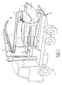
- the concrete-pumping device according to the invention shown in fig. 1 is embodied as a concrete-pumping truck.
- the actual concrete pump 2 is mounted between the chassis beams of the truck.
- the pump is provided with a feed funnel 3 into which concrete can be poured from a concrete mixer.
- the concrete is pressed byl the concrete pump 2 out of the feed funnel 3 into a pressure conduit 4.
- This pressure conduit 4 extends along a jib 5 so that concrete can be poured at distance and at height using a concrete-pumping vehicle 1.
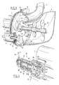
- each pump cylinder comprises a pump piston 10 which is connected to the plunger 11 of a hydraulic jack 14. Through suitable feed and discharge of hydraulic oil, as will be further described, the pump piston 10 can be moved reciprocally in the pump cylinder 6.
- the four pump cylinders 6-9 are assembled together with their associated hydraulic jacks into a unit mounted rotatably round a lengthwise shaft. This unit is rotatably mounted relative to the schematically indicated frame 16.
- the front ends of the pump cylinders 6-9 are fixedly welded for this purpose to a disc 20 such that the open ends of the pump cylinders 6-9 functioning as pump openings connect onto openings 26 in this disc 20.
- a rotary crown part 21 Along the edge of the disc 20 is arranged a rotary crown part 21.
- This rotary crown part 21 co-acts with a rotary crown part 22 arranged on a disc 29 fixedly connected to the frame.
- the disc 29 lies sealingly against the disc 20.
- kidney-shaped openings respectively a suction opening 28 on the underside and a pressure opening 27 on the upper part.
- a sealing 25 Arranged in the rotary crown part 21, 22 is a sealing 25 which prevents liquid leaking to the outside between the two discs 20, 29.
- a gear ring 23 Around the rotary crown part 21, 22 is mounted a gear ring 23. This gear ring 23 is in engagement with a pinion 24 which is driven by a hydrostatic motor 18 in a manner to be described later with reference to fig. 7.
- Hydraulic switching means 35 which bring about the reciprocating stroke of the hydraulic jacks are arranged at the opposite end of the rotatable unit and are shown in more detail in fig. 7.
- the hydraulic switching means 35 comprise a slide valve part 36 which is fixedly connected to the rotating unit and therefore co-rotates therewith.
- a second slide valve part 37 is connected to the frame and comprises a non-rotatable housing 46 and an positioning slide 38 mounted rotatably therein.
- Arranged in the housing 46 are a feed port 39 for hydraulic oil under pressure and a discharge port 40 for hydraulic oil.
- the feed port 39 communicates with a core channel 41 of the positioning slide 38.
- the core channel debouches into a pressure recess 42 in a disc-like head 48 of the positioning slide 38.
- the discharge port 40 communicates with a casing channel 43 formed between the housing 46 and the slide 38 itself.
- This casing channel 43 communicates in turn with a suction recess 44 of the head disc.
- the rotating part 36 of the hydraulic switching means 35 comprises a disc 47 which lies against the head disc 48 and wherein are formed four connecting ports 45 which are connected by suitable lines to the hydraulic jacks in the manner made clear in fig. 7.
- the respective connecting ports 45 come to lie alternatingly in front of the pressure recess 42 and the suction recess 44.
- FIG. 7 shows, two pump cylinders with hydraulic jacks lying diametrically opposite one another are connected in each case to form oppositely moving pairs 6, 8 and 7, 9.
- the spaces behind the plungers are mutually connected as by a line 13 while the spaces in front of the plungers are connected by suitable lines, such as line 12, to connecting ports 45 situated diametrically opposite each other.
- the connecting port 45 lying diametrically opposite is situated in front of the suction recess 44 so that hydraulic oil under pressure can flow via the feed port 39, the core channel 41 and the pressure recess 42 to one of the hydraulic jacks of the relevant pair on the front side of the plunger thereof.
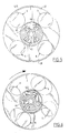
- Fig. 5 shows the position of the rotatable unit as shown in fig. 2.
- the pump cylinder 6 is rotated therein in the disc 29 just before the beginning of the kidney-shaped pressure opening 27 while the pump cylinder 7 is still situated just at the end of this pressure opening 27.
- Fig. 5 shows the position of the rotatable unit as shown in fig. 2.
- the pump cylinder 6 is rotated therein in the disc 29 just before the beginning of the kidney-shaped pressure opening 27 while the pump cylinder 7 is still situated just at the end of this pressure opening 27.
- the opening 45 associated with the pump cylinder 7 is still just in communication with the suction recess 44 while the opening 45 associated with the pump cylinder 9 is still just in communication with the pressure recess 42 of the hydraulic switching means 35.
- the pump cylinder 7 therefore carries out a pressure stroke while the pump cylinder 9 performs a suction stroke.
- all the hydraulic oil under pressure flows to the hydraulic jacks via the hydrostatic motor 18 which rotates the turning unit.
- This hydrostatic motor 18 is adjusted such that in the case of a complete revolution of the rotatable unit so much hydraulic oil has passed through the motor 18 that all the hydraulic jacks and therefore the pump cylinders have performed a complete reciprocating stroke and have thus returned to the starting position.
- each pump cylinder thus performs a pressure stroke as it passes along the pressure opening 27 and a suction stroke as it passes along the suction opening 28.
- the pump cylinder 7 is thus practically at the end of the pressure stroke while the pump cylinder 6 is located at the start of the pressure stroke.
- the pump cylinder 8 is likewise at the start of the suction stroke and the pump cylinder 9 at the end thereof.
- the hydraulic switching means 35 can be embodies such that the valve slide connected to the frame co-rotates each time with the rotatable unit through a small angle so that the mutual position of the openings 45 and the pressure and suction recesses remains unchanged roughly in the position as shown in fig. 6 until the relevant pump cylinder has fully completed the pressure stroke. At that moment the slide valve parts again move into their normal position whereby the pump cylinder ready for the pressure stroke is activated.
- a carrier construction which causes this path of movement can be embodied in many different ways such as, for example, with a curve-disc, a crank-drive rod mechanism or the like.
- the positioning slide 38 can perform the reciprocating rotation in a simple manner.
- the rotatable embodiment of the positioning slide 38 can be used for a rotation through 180 degrees.
- a lever 49 which can be operated manually or for example by an air cylinder.
- the pressure recess 42 and the suction recess 44 change places so that the cylinders which carry out a pressure stroke switch to a suction stroke and vice versa.
- This option is significant in eliminating blockages occurring in the pressure conduit 4 during operation.
- By turning the lever 49 back and forth pressure and suction occur alternately whereby a blockage can be rapidly eliminated.
- a stirring member 50 fixedly connected to the rotatable unit protrudes into the feed funnel 3. This ensures that the concrete in the feed funnel 3 remains well mixed.
Landscapes
- Engineering & Computer Science (AREA)
- Mechanical Engineering (AREA)
- General Engineering & Computer Science (AREA)
- Reciprocating Pumps (AREA)
- On-Site Construction Work That Accompanies The Preparation And Application Of Concrete (AREA)
Applications Claiming Priority (2)
| Application Number | Priority Date | Filing Date | Title |
|---|---|---|---|
| NL8902546A NL8902546A (nl) | 1989-10-13 | 1989-10-13 | Betonpompinrichting. |
| NL8902546 | 1989-10-13 |
Publications (2)
| Publication Number | Publication Date |
|---|---|
| EP0422745A1 true EP0422745A1 (de) | 1991-04-17 |
| EP0422745B1 EP0422745B1 (de) | 1995-04-05 |
Family
ID=19855454
Family Applications (1)
| Application Number | Title | Priority Date | Filing Date |
|---|---|---|---|
| EP90202724A Expired - Lifetime EP0422745B1 (de) | 1989-10-13 | 1990-10-11 | Betonpumpvorrichtung |
Country Status (6)
| Country | Link |
|---|---|
| US (1) | US5114319A (de) |
| EP (1) | EP0422745B1 (de) |
| JP (1) | JPH03185276A (de) |
| AT (1) | ATE120833T1 (de) |
| DE (1) | DE69018363T2 (de) |
| NL (1) | NL8902546A (de) |
Cited By (11)
| Publication number | Priority date | Publication date | Assignee | Title |
|---|---|---|---|---|
| AT403219B (de) * | 1995-02-01 | 1997-12-29 | Scheidl Rudolf Dipl Ing Dr Tec | Vorrichtung zum ansteuern eines hydrostatischen antriebes |
| EP0854285A3 (de) * | 1997-01-17 | 1999-11-24 | Gian Guido Ravellini | Betonpumpe |
| US6081983A (en) * | 1998-05-15 | 2000-07-04 | Apex Tool And Manufacturing, Inc. | Screw element extractor |
| WO2005085636A1 (de) * | 2004-02-26 | 2005-09-15 | Schwing Gmbh | Kolben-dickstoffpumpe |
| CN102220970A (zh) * | 2011-07-14 | 2011-10-19 | 长春工业大学 | 用于混凝土输送泵的防止堵泵结构 |
| CN103047508A (zh) * | 2012-12-25 | 2013-04-17 | 三一重工股份有限公司 | 一种物料输送系统及其管道切换装置 |
| CN103775300A (zh) * | 2014-02-20 | 2014-05-07 | 中联重科股份有限公司 | 泵送设备 |
| CN104389851A (zh) * | 2014-11-20 | 2015-03-04 | 徐州徐工施维英机械有限公司 | 液压限位装置以及混凝土泵车 |
| CN105626606A (zh) * | 2014-10-27 | 2016-06-01 | 中联重科股份有限公司 | 一种混凝土泵送设备液压系统及混凝土泵送设备 |
| CN109594780A (zh) * | 2018-12-10 | 2019-04-09 | 佛山科学技术学院 | 混泥土泵送装置 |
| CN115030513A (zh) * | 2022-05-31 | 2022-09-09 | 中国五冶集团有限公司 | 一种方便快捷的混凝土压浆装置 |
Families Citing this family (18)
| Publication number | Priority date | Publication date | Assignee | Title |
|---|---|---|---|---|
| DE19804863A1 (de) * | 1998-02-09 | 1999-08-12 | Putzmeister Ag | Schiebervorrichtung für eine Zweizylinder-Dickstoffpumpe |
| AU2002950421A0 (en) * | 2002-07-29 | 2002-09-12 | Combined Resource Engineering Pty Ltd | Fluid operating pump |
| NL1034431C2 (nl) * | 2007-09-27 | 2009-03-30 | Staring Beheer B V M | Slurriepomp. |
| US20090220358A1 (en) * | 2008-02-29 | 2009-09-03 | Putzmeister America, Inc. | Unequal length alternating hydraulic cylinder drive system for continuous material output flow with equal material output pressure |
| US20090252626A1 (en) * | 2008-04-08 | 2009-10-08 | Andre Salvaire | Rotary Distributor for Pressure Multiplier |
| JP5105202B2 (ja) * | 2008-06-23 | 2012-12-26 | 満男 大見 | 流動物搬送装置 |
| JP4924911B2 (ja) * | 2009-11-18 | 2012-04-25 | 満男 大見 | 流動物圧送装置 |
| WO2012088850A1 (zh) * | 2010-12-29 | 2012-07-05 | 湖南三一智能控制设备有限公司 | 一种物料输送系统及其输送管切换装置 |
| WO2015167615A1 (en) * | 2014-04-27 | 2015-11-05 | National Oilwell Varco, L.P. | Multi-cylinder hydraulically-driven pump system |
| US10197047B2 (en) * | 2014-06-11 | 2019-02-05 | Graco Minnesota, Inc. | Hydraulic proportioning system with flow divider |
| USD788883S1 (en) | 2015-04-16 | 2017-06-06 | Robert A Drake | Pressure relief valve for use with concrete pumping system |
| US9732739B2 (en) | 2015-04-16 | 2017-08-15 | Robert A Drake | Concrete pumping system having safety recirculation and method features |
| CN106968908B (zh) * | 2017-03-29 | 2020-06-30 | 长乐智睿恒创节能科技有限责任公司 | 一种平稳输送混凝土泵以及控制方法 |
| US11143173B2 (en) | 2018-01-20 | 2021-10-12 | William E. Howseman, Jr. | Hydraulically synchronized pumps where the hydraulic motor of the master pump hydraulically drives the hydraulic motor of the slave pump |
| CN109113762B (zh) * | 2018-07-24 | 2019-09-24 | 山东科技大学 | 一种无脉冲湿喷机 |
| CN109113763B (zh) * | 2018-07-24 | 2019-09-24 | 山东科技大学 | 无脉冲湿喷机 |
| CN113775178B (zh) * | 2021-09-10 | 2022-09-20 | 马国林 | 一种混凝土浇筑输送工艺 |
| CN119222362B (zh) * | 2024-12-02 | 2025-03-04 | 山东黄金矿业(玲珑)有限公司 | 矿井膏体充填多管路切换装置及方法 |
Citations (5)
| Publication number | Priority date | Publication date | Assignee | Title |
|---|---|---|---|---|
| US3295451A (en) * | 1965-11-10 | 1967-01-03 | James E Smith | Hydraulic power converter |
| US3663129A (en) * | 1970-09-18 | 1972-05-16 | Leon A Antosh | Concrete pump |
| FR2163145A5 (de) * | 1971-11-29 | 1973-07-20 | Boyle Bede Alfred | |
| DE3219882A1 (de) * | 1982-05-27 | 1983-12-01 | Maschinenfabrik Walter Scheele GmbH & Co KG, 4750 Unna-Massen | Betonpumpe |
| EP0249175A2 (de) * | 1986-06-13 | 1987-12-16 | Ab Asea-Atom | Pumpe |
Family Cites Families (11)
| Publication number | Priority date | Publication date | Assignee | Title |
|---|---|---|---|---|
| US3262395A (en) * | 1963-06-10 | 1966-07-26 | Jorge A Morando | Hydraulic transformer |
| US3279383A (en) * | 1965-01-06 | 1966-10-18 | Burnup And Sims Inc | Hydraulic powered mobile concrete pump assembly |
| US3367272A (en) * | 1967-01-03 | 1968-02-06 | James E. Smith | Hydraulic power converter |
| DE1703219B2 (de) * | 1968-04-19 | 1977-02-24 | Putzmeister GmbH, Chur (Schweiz) | Betonpumpe |
| US3650638A (en) * | 1969-12-19 | 1972-03-21 | Halliburton Co | Hydraulically powered pump having a precompression function |
| US4105373A (en) * | 1974-11-12 | 1978-08-08 | Fogt Industriemaschinenvertretung A.G. | Fluid distributor device for controlling an apparatus for pumping wet concrete and the like |
| US3981622A (en) * | 1974-11-20 | 1976-09-21 | Kelsey-Hayes Company | Hydraulic intensifier control system |
| EP0080385A1 (de) * | 1981-11-25 | 1983-06-01 | Hands-England Drilling Limited | Pumpensysteme |
| DE3219982A1 (de) * | 1982-05-27 | 1983-12-01 | Daimler-Benz Ag, 7000 Stuttgart | Schliesseinrichtung fuer eine klappe oder einen deckel an einem kraftfahrzeug |
| US4470771A (en) * | 1982-08-20 | 1984-09-11 | Towler Hydraulics, Inc. | Quadraplex fluid pump |
| GB8515944D0 (en) * | 1985-06-24 | 1985-07-24 | Normalair Garrett Ltd | Pressure intensifier device |
-
1989
- 1989-10-13 NL NL8902546A patent/NL8902546A/nl not_active Application Discontinuation
-
1990
- 1990-10-10 US US07/595,242 patent/US5114319A/en not_active Expired - Fee Related
- 1990-10-11 DE DE69018363T patent/DE69018363T2/de not_active Expired - Fee Related
- 1990-10-11 AT AT90202724T patent/ATE120833T1/de not_active IP Right Cessation
- 1990-10-11 EP EP90202724A patent/EP0422745B1/de not_active Expired - Lifetime
- 1990-10-12 JP JP2275135A patent/JPH03185276A/ja active Pending
Patent Citations (5)
| Publication number | Priority date | Publication date | Assignee | Title |
|---|---|---|---|---|
| US3295451A (en) * | 1965-11-10 | 1967-01-03 | James E Smith | Hydraulic power converter |
| US3663129A (en) * | 1970-09-18 | 1972-05-16 | Leon A Antosh | Concrete pump |
| FR2163145A5 (de) * | 1971-11-29 | 1973-07-20 | Boyle Bede Alfred | |
| DE3219882A1 (de) * | 1982-05-27 | 1983-12-01 | Maschinenfabrik Walter Scheele GmbH & Co KG, 4750 Unna-Massen | Betonpumpe |
| EP0249175A2 (de) * | 1986-06-13 | 1987-12-16 | Ab Asea-Atom | Pumpe |
Non-Patent Citations (1)
| Title |
|---|
| SOVIET INVENTIONS ILLUSTRATED,section Q,week 8515,22 mei 1985,class Q56,no 85-092080/15, SU-A-1116-209(SOYUZSPETSFUNDAMENT)22-06-1983 * |
Cited By (16)
| Publication number | Priority date | Publication date | Assignee | Title |
|---|---|---|---|---|
| AT403219B (de) * | 1995-02-01 | 1997-12-29 | Scheidl Rudolf Dipl Ing Dr Tec | Vorrichtung zum ansteuern eines hydrostatischen antriebes |
| EP0854285A3 (de) * | 1997-01-17 | 1999-11-24 | Gian Guido Ravellini | Betonpumpe |
| US6081983A (en) * | 1998-05-15 | 2000-07-04 | Apex Tool And Manufacturing, Inc. | Screw element extractor |
| WO2005085636A1 (de) * | 2004-02-26 | 2005-09-15 | Schwing Gmbh | Kolben-dickstoffpumpe |
| KR100816029B1 (ko) * | 2004-02-26 | 2008-03-21 | 슈빙 게엠베하 | 진한 물질 피스톤 펌프 |
| CN100439703C (zh) * | 2004-02-26 | 2008-12-03 | 施维英集团公司 | 一种稠物质活塞泵 |
| CN102220970A (zh) * | 2011-07-14 | 2011-10-19 | 长春工业大学 | 用于混凝土输送泵的防止堵泵结构 |
| CN102220970B (zh) * | 2011-07-14 | 2015-02-11 | 长春工业大学 | 用于混凝土输送泵的防止堵泵结构 |
| CN103047508B (zh) * | 2012-12-25 | 2015-04-22 | 三一汽车制造有限公司 | 一种物料输送系统及其管道切换装置 |
| CN103047508A (zh) * | 2012-12-25 | 2013-04-17 | 三一重工股份有限公司 | 一种物料输送系统及其管道切换装置 |
| CN103775300A (zh) * | 2014-02-20 | 2014-05-07 | 中联重科股份有限公司 | 泵送设备 |
| CN103775300B (zh) * | 2014-02-20 | 2016-08-17 | 中联重科股份有限公司 | 泵送设备 |
| CN105626606A (zh) * | 2014-10-27 | 2016-06-01 | 中联重科股份有限公司 | 一种混凝土泵送设备液压系统及混凝土泵送设备 |
| CN104389851A (zh) * | 2014-11-20 | 2015-03-04 | 徐州徐工施维英机械有限公司 | 液压限位装置以及混凝土泵车 |
| CN109594780A (zh) * | 2018-12-10 | 2019-04-09 | 佛山科学技术学院 | 混泥土泵送装置 |
| CN115030513A (zh) * | 2022-05-31 | 2022-09-09 | 中国五冶集团有限公司 | 一种方便快捷的混凝土压浆装置 |
Also Published As
| Publication number | Publication date |
|---|---|
| DE69018363T2 (de) | 1995-07-27 |
| JPH03185276A (ja) | 1991-08-13 |
| DE69018363D1 (de) | 1995-05-11 |
| NL8902546A (nl) | 1991-05-01 |
| ATE120833T1 (de) | 1995-04-15 |
| EP0422745B1 (de) | 1995-04-05 |
| US5114319A (en) | 1992-05-19 |
Similar Documents
| Publication | Publication Date | Title |
|---|---|---|
| EP0422745A1 (de) | Betonpumpvorrichtung | |
| US5993181A (en) | Process and device for feeding concrete or other thick materials | |
| US6171075B1 (en) | Process and device for controlling a two-cylinder thick medium pump | |
| EP0197632B1 (de) | Antrieb für Schlammkolbenpumpe | |
| EP0251076B1 (de) | Plattenvibrator | |
| US3667869A (en) | Dual cylinder-concrete pump | |
| US3939656A (en) | Hydrostatic transmission pump | |
| EP1455567B2 (de) | Dauerdosierung und -korrektur verwendende elektronische dosiervorrichtung | |
| JP4653096B2 (ja) | 連続的な流量の往復スラリーポンプ | |
| US3181469A (en) | Concrete pumping apparatus | |
| US4385869A (en) | Reciprocation pump | |
| US5671873A (en) | Proportioning apparatus for viscous materials | |
| US3749525A (en) | Hydraulically operated fluid aggregate pump | |
| US4621747A (en) | Apparatus for charge-wise dosing a metered volume quantity of a flowing medium continuously supplied to the apparatus under delivery pressure | |
| US3807706A (en) | Concrete handling arrangement | |
| US4569642A (en) | Slurry pump | |
| US4893992A (en) | Two-cylinder thick-material pump | |
| JPS6214715B2 (de) | ||
| RU2000124311A (ru) | Пресс с эксцентриковым кривошипным приводом блока верхнего пуансона и способ его работы | |
| DE4207566A1 (de) | Taumelscheibenpumpe mit variabler foerderleistung | |
| GB1291331A (en) | Concrete pump assemblies | |
| CN210186898U (zh) | 配液泵和配液装置 | |
| US3429267A (en) | Material pumping assembly | |
| KR20230130686A (ko) | 농후 물질 밸브와 농후 물질 밸브의 기동 방법 | |
| GB1335194A (en) | Apparatus operating on the positive displacement principle and usable as a fluid pump or as a motor |
Legal Events
| Date | Code | Title | Description |
|---|---|---|---|
| PUAI | Public reference made under article 153(3) epc to a published international application that has entered the european phase |
Free format text: ORIGINAL CODE: 0009012 |
|
| AK | Designated contracting states |
Kind code of ref document: A1 Designated state(s): AT BE CH DE DK ES FR GB GR IT LI LU NL SE |
|
| 17P | Request for examination filed |
Effective date: 19911011 |
|
| 17Q | First examination report despatched |
Effective date: 19930303 |
|
| ITF | It: translation for a ep patent filed | ||
| GRAA | (expected) grant |
Free format text: ORIGINAL CODE: 0009210 |
|
| AK | Designated contracting states |
Kind code of ref document: B1 Designated state(s): AT BE CH DE DK ES FR GB GR IT LI LU NL SE |
|
| PG25 | Lapsed in a contracting state [announced via postgrant information from national office to epo] |
Ref country code: LI Effective date: 19950405 Ref country code: GR Free format text: LAPSE BECAUSE OF FAILURE TO SUBMIT A TRANSLATION OF THE DESCRIPTION OR TO PAY THE FEE WITHIN THE PRESCRIBED TIME-LIMIT Effective date: 19950405 Ref country code: ES Free format text: THE PATENT HAS BEEN ANNULLED BY A DECISION OF A NATIONAL AUTHORITY Effective date: 19950405 Ref country code: DK Effective date: 19950405 Ref country code: CH Effective date: 19950405 Ref country code: BE Effective date: 19950405 Ref country code: AT Effective date: 19950405 |
|
| REF | Corresponds to: |
Ref document number: 120833 Country of ref document: AT Date of ref document: 19950415 Kind code of ref document: T |
|
| REF | Corresponds to: |
Ref document number: 69018363 Country of ref document: DE Date of ref document: 19950511 |
|
| ET | Fr: translation filed | ||
| PG25 | Lapsed in a contracting state [announced via postgrant information from national office to epo] |
Ref country code: SE Effective date: 19950705 |
|
| REG | Reference to a national code |
Ref country code: CH Ref legal event code: PL |
|
| PG25 | Lapsed in a contracting state [announced via postgrant information from national office to epo] |
Ref country code: LU Free format text: LAPSE BECAUSE OF NON-PAYMENT OF DUE FEES Effective date: 19951031 |
|
| PLBE | No opposition filed within time limit |
Free format text: ORIGINAL CODE: 0009261 |
|
| STAA | Information on the status of an ep patent application or granted ep patent |
Free format text: STATUS: NO OPPOSITION FILED WITHIN TIME LIMIT |
|
| 26N | No opposition filed | ||
| PGFP | Annual fee paid to national office [announced via postgrant information from national office to epo] |
Ref country code: FR Payment date: 19991228 Year of fee payment: 10 |
|
| PGFP | Annual fee paid to national office [announced via postgrant information from national office to epo] |
Ref country code: GB Payment date: 20000128 Year of fee payment: 10 |
|
| PG25 | Lapsed in a contracting state [announced via postgrant information from national office to epo] |
Ref country code: GB Free format text: LAPSE BECAUSE OF NON-PAYMENT OF DUE FEES Effective date: 20001011 |
|
| GBPC | Gb: european patent ceased through non-payment of renewal fee |
Effective date: 20001011 |
|
| PG25 | Lapsed in a contracting state [announced via postgrant information from national office to epo] |
Ref country code: FR Free format text: LAPSE BECAUSE OF NON-PAYMENT OF DUE FEES Effective date: 20010629 |
|
| REG | Reference to a national code |
Ref country code: FR Ref legal event code: ST |
|
| PG25 | Lapsed in a contracting state [announced via postgrant information from national office to epo] |
Ref country code: IT Free format text: LAPSE BECAUSE OF NON-PAYMENT OF DUE FEES;WARNING: LAPSES OF ITALIAN PATENTS WITH EFFECTIVE DATE BEFORE 2007 MAY HAVE OCCURRED AT ANY TIME BEFORE 2007. THE CORRECT EFFECTIVE DATE MAY BE DIFFERENT FROM THE ONE RECORDED. Effective date: 20051011 |
|
| PGFP | Annual fee paid to national office [announced via postgrant information from national office to epo] |
Ref country code: NL Payment date: 20070430 Year of fee payment: 17 Ref country code: DE Payment date: 20070430 Year of fee payment: 17 |
|
| NLV4 | Nl: lapsed or anulled due to non-payment of the annual fee |
Effective date: 20080501 |
|
| PG25 | Lapsed in a contracting state [announced via postgrant information from national office to epo] |
Ref country code: DE Free format text: LAPSE BECAUSE OF NON-PAYMENT OF DUE FEES Effective date: 20080501 |
|
| PG25 | Lapsed in a contracting state [announced via postgrant information from national office to epo] |
Ref country code: NL Free format text: LAPSE BECAUSE OF NON-PAYMENT OF DUE FEES Effective date: 20080501 |