EP0422746B1 - Dispositif de séparation expulsif amélioré - Google Patents
Dispositif de séparation expulsif amélioré Download PDFInfo
- Publication number
- EP0422746B1 EP0422746B1 EP90202729A EP90202729A EP0422746B1 EP 0422746 B1 EP0422746 B1 EP 0422746B1 EP 90202729 A EP90202729 A EP 90202729A EP 90202729 A EP90202729 A EP 90202729A EP 0422746 B1 EP0422746 B1 EP 0422746B1
- Authority
- EP
- European Patent Office
- Prior art keywords
- expulsive
- conductor means
- blanket
- electro
- insulating layer
- Prior art date
- Legal status (The legal status is an assumption and is not a legal conclusion. Google has not performed a legal analysis and makes no representation as to the accuracy of the status listed.)
- Expired - Lifetime
Links
- 238000000926 separation method Methods 0.000 title description 4
- 239000004020 conductor Substances 0.000 claims abstract description 78
- 239000000463 material Substances 0.000 claims abstract description 15
- 239000007787 solid Substances 0.000 claims abstract description 9
- 238000002844 melting Methods 0.000 claims description 11
- 230000008018 melting Effects 0.000 claims description 11
- 239000012212 insulator Substances 0.000 claims description 6
- 238000005304 joining Methods 0.000 claims description 4
- 230000001846 repelling effect Effects 0.000 claims description 4
- 229920001169 thermoplastic Polymers 0.000 claims description 4
- 239000000615 nonconductor Substances 0.000 claims description 2
- 230000004044 response Effects 0.000 claims description 2
- 238000000034 method Methods 0.000 abstract description 2
- 239000011800 void material Substances 0.000 abstract 1
- 239000010410 layer Substances 0.000 description 41
- KAKZBPTYRLMSJV-UHFFFAOYSA-N Butadiene Chemical compound C=CC=C KAKZBPTYRLMSJV-UHFFFAOYSA-N 0.000 description 4
- 230000008901 benefit Effects 0.000 description 4
- 239000012815 thermoplastic material Substances 0.000 description 4
- WYTGDNHDOZPMIW-RCBQFDQVSA-N alstonine Natural products C1=CC2=C3C=CC=CC3=NC2=C2N1C[C@H]1[C@H](C)OC=C(C(=O)OC)[C@H]1C2 WYTGDNHDOZPMIW-RCBQFDQVSA-N 0.000 description 3
- 238000009826 distribution Methods 0.000 description 3
- 229920002635 polyurethane Polymers 0.000 description 3
- 239000004814 polyurethane Substances 0.000 description 3
- 239000000126 substance Substances 0.000 description 3
- RYGMFSIKBFXOCR-UHFFFAOYSA-N Copper Chemical compound [Cu] RYGMFSIKBFXOCR-UHFFFAOYSA-N 0.000 description 2
- 239000004698 Polyethylene Substances 0.000 description 2
- 230000009471 action Effects 0.000 description 2
- 230000003466 anti-cipated effect Effects 0.000 description 2
- 229910052802 copper Inorganic materials 0.000 description 2
- 239000010949 copper Substances 0.000 description 2
- 230000007423 decrease Effects 0.000 description 2
- 230000000694 effects Effects 0.000 description 2
- 229920001971 elastomer Polymers 0.000 description 2
- 239000000806 elastomer Substances 0.000 description 2
- 239000013536 elastomeric material Substances 0.000 description 2
- 230000005484 gravity Effects 0.000 description 2
- 238000010438 heat treatment Methods 0.000 description 2
- 238000009413 insulation Methods 0.000 description 2
- 230000004048 modification Effects 0.000 description 2
- 238000012986 modification Methods 0.000 description 2
- 230000000737 periodic effect Effects 0.000 description 2
- -1 polyethylene Polymers 0.000 description 2
- 229920000573 polyethylene Polymers 0.000 description 2
- 229920005989 resin Polymers 0.000 description 2
- 239000011347 resin Substances 0.000 description 2
- 230000003068 static effect Effects 0.000 description 2
- BFKJFAAPBSQJPD-UHFFFAOYSA-N tetrafluoroethene Chemical compound FC(F)=C(F)F BFKJFAAPBSQJPD-UHFFFAOYSA-N 0.000 description 2
- 229920005992 thermoplastic resin Polymers 0.000 description 2
- 239000002390 adhesive tape Substances 0.000 description 1
- 238000004378 air conditioning Methods 0.000 description 1
- 230000009286 beneficial effect Effects 0.000 description 1
- 239000003990 capacitor Substances 0.000 description 1
- 239000003245 coal Substances 0.000 description 1
- 239000011247 coating layer Substances 0.000 description 1
- 238000000576 coating method Methods 0.000 description 1
- 239000002131 composite material Substances 0.000 description 1
- 230000006835 compression Effects 0.000 description 1
- 238000007906 compression Methods 0.000 description 1
- 238000007599 discharging Methods 0.000 description 1
- 238000010292 electrical insulation Methods 0.000 description 1
- 239000000945 filler Substances 0.000 description 1
- 239000011888 foil Substances 0.000 description 1
- 230000006870 function Effects 0.000 description 1
- 230000003116 impacting effect Effects 0.000 description 1
- 230000006872 improvement Effects 0.000 description 1
- 239000007788 liquid Substances 0.000 description 1
- 239000007791 liquid phase Substances 0.000 description 1
- 238000004519 manufacturing process Methods 0.000 description 1
- 230000013011 mating Effects 0.000 description 1
- 239000002184 metal Substances 0.000 description 1
- 229910052751 metal Inorganic materials 0.000 description 1
- 230000035939 shock Effects 0.000 description 1
- 239000002356 single layer Substances 0.000 description 1
- 238000005507 spraying Methods 0.000 description 1
- 238000010408 sweeping Methods 0.000 description 1
- XLYOFNOQVPJJNP-UHFFFAOYSA-N water Substances O XLYOFNOQVPJJNP-UHFFFAOYSA-N 0.000 description 1
- 238000003466 welding Methods 0.000 description 1
Images


Classifications
-
- B—PERFORMING OPERATIONS; TRANSPORTING
- B64—AIRCRAFT; AVIATION; COSMONAUTICS
- B64D—EQUIPMENT FOR FITTING IN OR TO AIRCRAFT; FLIGHT SUITS; PARACHUTES; ARRANGEMENT OR MOUNTING OF POWER PLANTS OR PROPULSION TRANSMISSIONS IN AIRCRAFT
- B64D15/00—De-icing or preventing icing on exterior surfaces of aircraft
- B64D15/16—De-icing or preventing icing on exterior surfaces of aircraft by mechanical means, e.g. pulsating mats or shoes attached to, or built into, surface
-
- B—PERFORMING OPERATIONS; TRANSPORTING
- B64—AIRCRAFT; AVIATION; COSMONAUTICS
- B64D—EQUIPMENT FOR FITTING IN OR TO AIRCRAFT; FLIGHT SUITS; PARACHUTES; ARRANGEMENT OR MOUNTING OF POWER PLANTS OR PROPULSION TRANSMISSIONS IN AIRCRAFT
- B64D15/00—De-icing or preventing icing on exterior surfaces of aircraft
- B64D15/16—De-icing or preventing icing on exterior surfaces of aircraft by mechanical means, e.g. pulsating mats or shoes attached to, or built into, surface
- B64D15/163—De-icing or preventing icing on exterior surfaces of aircraft by mechanical means, e.g. pulsating mats or shoes attached to, or built into, surface using electro-impulsive devices
-
- H—ELECTRICITY
- H01—ELECTRIC ELEMENTS
- H01F—MAGNETS; INDUCTANCES; TRANSFORMERS; SELECTION OF MATERIALS FOR THEIR MAGNETIC PROPERTIES
- H01F7/00—Magnets
- H01F7/06—Electromagnets; Actuators including electromagnets
- H01F7/20—Electromagnets; Actuators including electromagnets without armatures
- H01F7/202—Electromagnets for high magnetic field strength
Definitions
- the present invention relates to an electro-expulsive device comprising: a flexible blanket having first and second outer walls, at least two separable electrical conductor means enclosed within said blanket, said conductor means having a first position defining a rest position and a second position defining an energized position, an intermediate layer sandwiched between said conductor means, elastic connector means within said blanket for joining the first and second walls to said intermediate layer at spaced intervals whereby said conductor means are separable in accordance with a predetermined pattern under control of said connector means in response to repelling forces created by a magnetic field developed when said electrical conductor means are energized by an electric current, and insulating means provided to support the creation of voids when said repelling forces are generated.
- the known apparatus provides an electro-expulsive device by which solid or frangible matter such as ice may be shed from the device by forcing a current to flow through the separable conductor means.
- the creation of voids is supported by the insulating means which are present within these voids and which do not bond to the material of the outer walls.
- several thin release films are inserted between the conductor means at the locations where the voids are desired.
- the electro-expulsive device is characterized in that said insulating means comprises a first and a second insulating layer, the first insulating layer being arranged between said intermediate layer and the first wall and the second insulating layer being arranged between said intermediate layer and the second wall,
- said first and second insulating layer are continuous except for several first perforations in the first insulating layer and for several second perforations in the second insulating layer, respectively, the first and second perforations being grouped in rows extending in the longitudinal direction of the conductor means and adjacent to said conductor means, said connector means comprise first connector means which extend through the first perforations and second connector means which extend through the second perforations, respectively.
- the connector means through the perforations are, advantageously, accomplished by controlled heating and melting of the thermoplastic resin of the blanket so that molten resin flows into the respective perforations thereby joining the outer walls with the intermediate layer as described.
- said first perforations in said first insulating layer are offset longitudinally relative to the second perforations in said second insulating layer.
- a periodically varying spring gradient in the longitudinal axis of the conductor runs is provided.
- the periodic variation of the spring gradient creates a mild serpentine or sinusoidal deformation in the longitudinal dimension of the outer conductor, which supports to achieve minimal stress throughout the conductor of the outer layer and therefore supports the effective life of the conductor and the blanket.
- the conductor means comprises first and second conductor means, which run on opposite sides of the intermediate layer and the first conductor means is in direct contact with the first insulating layer and the second conductor means is in direct contact with the second insulating layer.
- the insulator means are thermal and electrical insulators fabricated of a thermoplastic polymer having a melting point greater than the melting point of the thermoplastic polymer from which the blanket, the connector means and the intermediate layer are fabricated.
- the first and second conductor means may each define at least one generally flat, continuous ribbon patterned to define elongated ribbon portions spaced by intervening elongated gaps, while the connector means may be spaced along said ribbon portions and may be disposed in said intervening gaps.
- the electric current supplied to the conductor means preferably, has such a shape that a force of sufficient magnitude is generated to expulse solid or frangible material bonded to the surface of the electro-expulsive device during a time interval of 10 to 80 microseconds.
- the beneficial property is that initially (during the first 80 micro-seconds of an applied force) the effective modulus of compression (Young's Modulus) of such elastomeric materials is much greater than the modulus values assigned in the usual and customary specifications contained in standard chemical handbooks and chemical dictionaries. That is, initially, the materials are virtually solid.
- the invention takes advantage of this property by applying a very high current to the conductors of the blanket for a very short time and thereby forcing the surface of the blanket to move almost exactly the same distance as the internal conductor has moved.
- the initial high modulus of the elastomer makes it almost incompressible in the short term giving the blanket surface a gain motion in a ratio of nearly 1 to 1 relative to the corresponding surface motion of the underlying conductor.
- the extremely high force with minimal motion, fractures the crystalline ice (or other frangible material) at the blanket surface and destroys the bond between the ice and the blanket. Mind velocity or gravity then cause the ice to be shed.
- a method of expulsing solid or frangible material bonded to a surface may comprise the steps of impacting the material abruptly with a force of sufficient magnitude to break the bond between the material and the surface, and, sustaining the force for an interval ranging from 10 to 80 microseconds.
- the very short pulse contributes to blanket life by limiting the motion required to successfully de-ice. In the earliest portions of the expulsive pulse little metal (copper) or elastomer deformation takes place. Since fatigue damage to both materials is strongly related to total material deformation, the shortened pulse is not only efficient of energy, but provides extended life for all blanket geometries by reducing fatigue damage per cycle.
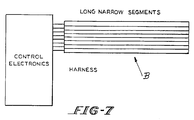
- a long, narrow, thin (0,76.10 ⁇ 3 m (0,030 inch) to 2,03.10 ⁇ 3 m (0,080 inch) thick) blanket geometry is provided wherein all electrical connections between electronics and blanket are made at one end.
- This improvement drastically reduces the weight of the leads required to connect blankets to electronics.
- Blankets are made in long, narrow strips for convenience. To cover a particular surface, multiple segments are laid out side by side with their long dimensions abutting. After these segments have been affixed to the surface to be protected, a thin covering or coating layer of adhesive tape such as polyethylene, a conformal layer of metallic foil or a spray coating of filler material is applied over all the segments to provide a smooth continuous outer surface.
- All segment connections are at the narrow end.
- the driver electronics are placed so as to be closest to the connection end.
- harness connection must be made at increasingly large distances as segments get further from the electronics which fires them.
- the harness length is minimized which in turn minimizes weight.
- low ice shedding threshold voltage is provided while at the same time long operational blanket life is obtained.
- This is achieved by controlling the local spring rate throughout the active region of a blanket segment. Inherently the spring rate varies in the space between blanket wall connector means so that blanket deformation varies; correspondingly, the metallic conductor deformation varies.
- the result of locally controlled spring rates is to provide non-uniform dynamic conductor deformation and therefore non-uniform blanket deformation during the time when the blanket is fired. This leads to long life of the total apparatus.
- the gradient should be nearly zero so that all energy is converted into momentum of the outer (top) conductor and its mating wall.
- the repulsive force diminishes because of the increased distance and because the current decreases as the discharging capacitor voltage decreases.
- a preferred means of achieving this type behavior is by bonding the top (outer) wall of the blanket to the bottom (outer) wall of the blanket using an intermediate layer of elastomeric material disposed between the top and bottom walls.
- This intermediate layer is bonded to top and bottom walls through offset perforations or holes in two separating high melting thermo-electric insulators.
- a first set of perforations in a first insulator permit a connection from the bottom wall to the intermediate layer.
- a second set of perforations in a second insulator, preferably offset from said first set of perforations, permit a connection between the top wall and the intermediate layer.
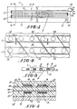
- the reference numeral 11 designates an expulsive separation apparatus comprising a blanket 12 of thermo plastic material such as polyurethane, polyethelyne and butadiene enclosing elongated continuous ribbon-like conductor means 13 and 14.
- the conductor means 13 and 14 include ribbon portions 16 with intervening spaces 17, and top conductor means 13 is aligned generally with bottom conductor means 14.
- each conductor means 13 and 14 comprise stacks of flat metallic continuous ribbons indicated generally by the reference numerals 18 and 19 respectively.
- the ribbons 18 and 19, in the disclosed embodiment, are three in number and range in thickness from 25,4.10 ⁇ 6 m (0,001 inches) to 25,4.10 ⁇ 5 m (0,010 inches).
- ribbons of the present disclosure are fabricated of copper, it is anticipated that other suitable electrical conductors may be substituted.
- the ribbon stacks 18 and 19 may comprise single or multiple layers.
- Each ribbon portion of each stack are joined as at 20 ( Figure I) and includes a tab portion such as at 21, facilitating a spot electrical connector 22 providing electrical continuity between top conductor means 13 and bottom conductor means 14.
- Top conductor means 13 is connected to positive lead 23 and bottom conductor means 14 terminates at negative lead 24.
- the polyurethane of blanket 12 surrounds the conductor means 13 and 14 so as to define a first outer wall 26, a second outer wall 27 and an intermediate layer 28.
- the main body of the conductor means 13 and 14 are isolated further by insulation means defining two layers 29 and 31 of high melting thermoplastic material such as TEFLON (tetrafluoroethylene).
- TEFLON tetrafluoroethylene
- the blanket 12 be fabricated of thermoplastic material of low melting point relative to the melting point of the insulator means.
- Insulating layer 29 is formed with perforation 32 and insulating layer 31 is formed with perforation 33.
- the perforations 32 and 33 are offset from one another along the longitudinal axis of the blanket 12 and fall with the spaces or gaps 17 between ribbon stacks as shown in Figures 2 and 4.
- This disposition of the perforations in insulating layers 29 and 31 makes it possible to provide connector means between the first outer wall 26 and the intermediate layer 28, and between the second outer wall 27 and the intermediate layer 28.
- the connector means is defined further by the pillars or posts 34 and 36, respectively.
- thermoplastic resin of the blanket 12 This connection is accomplished by controlled heating and melting of the thermoplastic resin of the blanket 12 so that molten resin flows into the respective perforations 32 and 33 thereby joining the outer walls with the intermediate layer in the fashion described above.
- the high melting electrical and thermal insulating layers 29 and 31 preclude welding between the outer walls and the intermediate layer except at the location of the perforations.
- first outer wall 26 is joined to the intermediate layer 28 by posts 34 and the second outer wall 27 is joined to the intermediate layer 28 by posts 36, as is apparent in the enlarged fragmentary sectional view of Figures 5 and 6.
- a blanket segment is shown in the at rest position secured to a surface S, such as the wing of an aircraft, with the second outer wall 27 abutting the surface S and the first outer wall 26 exposed to weather W.
- conductor means 13 and 14 Periodically the conductor means are energized causing conductor means 13 and 14 to repel one another under control of the posts 34 and 36.
- thermoplastic material from which the posts are fabricated permits the posts to elongate and to provide a restoring force returning the blanket to the rest position of Figure 5 when the conductor means are de-energized.
- the restoring force is enhanced by the action of static pressure against the vacuum created in voids 37 and 38 when the blanket is energized.
- the outer conductor means 13 assumes a serpentine configuration ( Figure 6) causing accumulated solid or frangible matter such as ice to be shattered breaking the bond between the ice, the outer wall 26 whereupon the ice disappears due to the force of gravity and the action of air currents sweeping over the wall 26.
- the blanket apparatus of the present invention can be fabricated of any desired length, with a variety of configurations of the conductor means, using any suitable conductive material, and blanket material so long as the thermal and electrical insulation means (29 and 31) operates to permit separation of the blanket walls in the fashion described and disclosed.
- the thickness of the composite blanket be thin and blankets having a thickness ranging from 0,76.10 ⁇ 3 m (0,030 inches) to 2,03.10 ⁇ 3 m (0,080 inches) operate in satisfactory fashion.
- the long narrow configuration of blankets B minimizes electrical harness requirements and makes it possible to have a short span between the control unit and the blanket pattern.
Landscapes
- Engineering & Computer Science (AREA)
- Physics & Mathematics (AREA)
- Electromagnetism (AREA)
- Mechanical Engineering (AREA)
- Aviation & Aerospace Engineering (AREA)
- Power Engineering (AREA)
- Centrifugal Separators (AREA)
- Forklifts And Lifting Vehicles (AREA)
- Steering Control In Accordance With Driving Conditions (AREA)
- Insulated Conductors (AREA)
- External Artificial Organs (AREA)
- Organic Insulating Materials (AREA)
- Infusion, Injection, And Reservoir Apparatuses (AREA)
Claims (8)
- Dispositif d'électro-expulsion (11) comprenant :- une enveloppe flexible (12) ayant une première et une deuxième parois extérieures (26, 27),- au moins deux éléments électriquement conducteurs séparables (13, 14) à l'intérieur de la dite enveloppe, les dits éléments conducteurs (13, 14) ayant une première position définissant une position de repos, et une deuxième position définissant une position d'excitation,- une couche intermédiaire (28) en sandwich entre les dits éléments conducteurs (13, 14),- des moyens de connexion élastiques (34, 36) à l'intérieur de la dite enveloppe (12) pour relier les première et deuxième parois (26, 27) à la dite couche intermédiaire (28), a des intervalles espacés par lesquels les dits éléments conducteurs (13, 14) sont séparables conformément à un schéma prédéterminé, sous le contrôle des dits moyens de connexion (34, 36), en réponse à des forces de répulsion créées par un champ magnétique développé quand les dits éléments électriquement conducteurs sont traversés par un courant électrique, et- des moyens d'isolation (29, 31) pour supporter la création de vides quand les dites forces de répulsion sont produites,
caractérisé en ce que :- les dits moyens d'isolation (29, 31) comprennent une première (29) et une seconde (31) couches isolantes, la première couche isolante (29) étant disposée entre la dite couche intermédiaire (28) et la première paroi (26), et la seconde couche isolante (31 étant disposée entre la dite couche intermédiaire (28) et la deuxième paroi (27),- les dites première (29) et seconde (31) couches isolantes sont continues, à l'exception, respectivement, de plusiers premières perforations (32) dans la première couche isolante (29) et de plusieurs secondes perforations (33) dans la seconde couche isolante (31), les premières (32) et secondes (33) perforations étant regroupées en lignes s'étendant dans la direction longitudinale des éléments conducteurs (13, 14) et à côté de les dits éléments conducteurs (13, 14), et- les dits éléments conducteurs comprennent des premiers moyens de connexion (34) qui s'étendent respectivement au travers des premières perforations (32), et des seconds moyens de connexions (36) qui s'étendent respectivement au travers des secondes perforations (33). - Dispositif selon la revendication 1, caractérisé en ce que les dites premières perforations (32) dans la dite première couche isolante (29) sont décalées par rapport aux secondes perforations (33) dans la dite seconde couche isolante (31).
- Dispositif selon l'une des revendications 1 ou 2, caractérisé en ce que les éléments conducteurs comprennent un premier (13) et un deuxième (14) éléments conducteurs, qui s'étendent sur des côtés opposés de la couche intermédiaire (28), le premier élément conducteur (13) étant en contact direct avec la première couche isolante (29), et le deuxième élément conducteur (14) étant en contact direct avec la seconde couche isolante (31).
- Dispositif selon l'une des revendications précédentes caractérisé en ce que les premier (29) et deuxième (31) moyens d'isolation sont des isolants thermiques et électriques fabriqués en un polymère thermoplastique ayant un point de fusion plus élevé que le point de fusion du polymère thermoplastique à partir duquel sont fabriqués l'enveloppe (12), les moyens de connexion (34, 36) et la couche intermédiaire (28).
- Dispositif selon l'une des revendications précédentes, caractérisé en ce que le premier (13) et le deuxième (14) éléments conducteurs définissent chacun au moins un ruban continu, généralement plat, dessiné pour définir des portions de ruban allongées (16) séparées par des interstices allongés intermédiaires (17).
- Dispositif selon la revendication 5, caractérisé en ce que les dits premiers (34) et second (36) moyens de connexions sont espacés le long des dites portions de ruban (16) et disposés dans les dits interstices intermédiaires (17).
- Dispositif selon l'une des revendications précédentes, caractérisé en ce que les dits premiers (34) et seconds (36) moyens de connexion ont une mémoire élastique qui fournit une force de rétablissement tendant à ramener les dits éléments conducteurs à la position de repos quand ils sont déexcités.
- Dispositif selon l'une des revendications précédentes, caractérisé en ce que le courant électrique fourni aux éléments conducteurs (13, 14) a une forme telle qu'une force de magnitude suffisante est produite pour expulser des matériaux solides ou frangibles déposés à la surface du dispositif d'électro-expulsion, en un intervalle de temps de 10 à 80 microsecondes.
Applications Claiming Priority (2)
| Application Number | Priority Date | Filing Date | Title |
|---|---|---|---|
| US07/421,053 US4982121A (en) | 1988-06-13 | 1989-10-13 | Expulsive separation apparatus |
| US421053 | 1989-10-13 |
Publications (3)
| Publication Number | Publication Date |
|---|---|
| EP0422746A2 EP0422746A2 (fr) | 1991-04-17 |
| EP0422746A3 EP0422746A3 (en) | 1992-01-08 |
| EP0422746B1 true EP0422746B1 (fr) | 1995-02-08 |
Family
ID=23668992
Family Applications (1)
| Application Number | Title | Priority Date | Filing Date |
|---|---|---|---|
| EP90202729A Expired - Lifetime EP0422746B1 (fr) | 1989-10-13 | 1990-10-12 | Dispositif de séparation expulsif amélioré |
Country Status (4)
| Country | Link |
|---|---|
| US (1) | US4982121A (fr) |
| EP (1) | EP0422746B1 (fr) |
| AT (1) | ATE118196T1 (fr) |
| DE (1) | DE69016736T2 (fr) |
Families Citing this family (22)
| Publication number | Priority date | Publication date | Assignee | Title |
|---|---|---|---|---|
| RU2096269C1 (ru) * | 1989-04-13 | 1997-11-20 | Игорь Анатольевич Левин | Способ удаления отложений, преимущественно льда, с очищаемой поверхности обшивки и устройство для его осуществления |
| US5107154A (en) * | 1990-12-19 | 1992-04-21 | Dataproducts New England, Incorporated | Electro-expulsive apparatus and method |
| US5143325B1 (en) * | 1991-01-03 | 2000-09-05 | Electroimpact Inc | Electromagnetic repulsion system for removing contaminants such as ice from the surface of aircraft and other objects |
| US5272400A (en) * | 1992-05-26 | 1993-12-21 | Dataproducts New England, Inc. | Expulsive ice detector |
| US5326051A (en) * | 1992-06-30 | 1994-07-05 | The B. F. Goodrich Company | Electro-expulsive deicing system having circuit board expulsive members |
| US5346160A (en) * | 1992-06-30 | 1994-09-13 | The B. F. Goodrich Company | Electro-expulsive deicing system having fail safe conductive bridge means |
| US5558304A (en) * | 1994-03-14 | 1996-09-24 | The B. F. Goodrich Company | Deicer assembly utilizing shaped memory metals |
| US5553815A (en) * | 1994-04-07 | 1996-09-10 | The B. F. Goodrich Company | De-icer adapted for installment on the inner surface of a structural member |
| US5531405A (en) * | 1994-08-23 | 1996-07-02 | Dynamics Controls Corporation | Method of building an expulsive blanket using composite materials and stitched attachment |
| US5657952A (en) * | 1995-07-31 | 1997-08-19 | Dynamic Controls Hs, Inc. | Electro-expulsive de-icing apparatus and method of use |
| DE102004011030B4 (de) * | 2004-03-04 | 2006-04-13 | Siemens Ag | Verkleidung mit integriertem Polymeraktor zur Verformung derselben |
| US8100364B2 (en) * | 2009-01-15 | 2012-01-24 | Textron Innovations Inc. | Anti-icing piccolo tube standoff |
| US9108735B2 (en) * | 2009-05-13 | 2015-08-18 | Tmc Aerospace, Inc. | Electro-expulsive de-icing system for aircraft and other applications |
| GB2472053A (en) * | 2009-07-23 | 2011-01-26 | Rolls Royce Plc | Aircraft and engine deicing apparatus |
| US9580181B2 (en) * | 2010-09-28 | 2017-02-28 | Saab Ab | Method and arrangement for de-icing a structural element |
| US8998144B2 (en) * | 2012-02-06 | 2015-04-07 | Textron Innovations Inc. | Thermal insulation barrier for an aircraft de-icing heater |
| US9067685B2 (en) * | 2012-04-18 | 2015-06-30 | Zodiac Aerotechnics | De-icing systems and methods |
| WO2014088481A1 (fr) * | 2012-12-06 | 2014-06-12 | Saab Ab | Agencement de dégivrage et procédé pour dégivrer un élément structurel |
| US20140252172A1 (en) * | 2013-03-05 | 2014-09-11 | Parviz Acquisitions Llc | Single surface electro-mechanical actuator assembly |
| US9889940B2 (en) | 2016-02-16 | 2018-02-13 | Peter Lenkey | Deicing apparatuses comprising at least one standoff |
| US10408378B2 (en) * | 2017-07-17 | 2019-09-10 | Raytheon Company | Three-dimensional multi-shell insulation |
| US12037122B2 (en) * | 2022-04-05 | 2024-07-16 | Goodrich Corporation | Systems and methods for an ice runback control zone in an electrothermal ice protection system |
Family Cites Families (10)
| Publication number | Priority date | Publication date | Assignee | Title |
|---|---|---|---|---|
| GB505433A (en) * | 1937-11-05 | 1939-05-05 | Rudolf Goldschmidt | Improvements in and relating to de-icing equipment, for example for aircraft |
| DE1216956B (de) * | 1962-10-02 | 1966-05-18 | Licentia Gmbh | Anordnung zur Beseitigung der Vereisung an Hochspannungs-Freileitungsseilen |
| US3549964A (en) * | 1968-03-01 | 1970-12-22 | Levin Igor A | Device for deicing surfaces of thin-walled structures |
| SU615560A1 (ru) * | 1977-02-15 | 1978-07-15 | Государственный Союзный Завод По Механической И Химической Очистке Котлоагрегатов "Котлоочистка" | Устройство дл удалени льда |
| JPS6010492B2 (ja) * | 1977-07-07 | 1985-03-18 | 日立電線株式会社 | 送電線着雪防止装置 |
| DE3462112D1 (en) * | 1983-08-24 | 1987-02-26 | Short Brothers Ltd | A method of and apparatus for de-icing an elastically deformable sheet member |
| US4678144A (en) * | 1984-10-26 | 1987-07-07 | Simmonds Precision | Electro-impulse de-icing system for aircraft |
| US4690353A (en) * | 1985-05-31 | 1987-09-01 | The United States Of America As Represented By The Administrator Of The National Aeronautics And Space Administration | Electro-expulsive separation system |
| US4894569A (en) * | 1988-06-13 | 1990-01-16 | Dataproducts New England, Inc. | Electro-expulsive separation apparatus |
| US4875644A (en) * | 1988-10-14 | 1989-10-24 | The B. F. Goodrich Company | Electro-repulsive separation system for deicing |
-
1989
- 1989-10-13 US US07/421,053 patent/US4982121A/en not_active Expired - Lifetime
-
1990
- 1990-10-12 DE DE69016736T patent/DE69016736T2/de not_active Expired - Lifetime
- 1990-10-12 EP EP90202729A patent/EP0422746B1/fr not_active Expired - Lifetime
- 1990-10-12 AT AT90202729T patent/ATE118196T1/de not_active IP Right Cessation
Also Published As
| Publication number | Publication date |
|---|---|
| DE69016736D1 (de) | 1995-03-23 |
| US4982121A (en) | 1991-01-01 |
| EP0422746A2 (fr) | 1991-04-17 |
| EP0422746A3 (en) | 1992-01-08 |
| ATE118196T1 (de) | 1995-02-15 |
| DE69016736T2 (de) | 1995-06-01 |
Similar Documents
| Publication | Publication Date | Title |
|---|---|---|
| US4982121A (en) | Expulsive separation apparatus | |
| US4690353A (en) | Electro-expulsive separation system | |
| US5782435A (en) | Electro-magnetic expulsion de-icing system | |
| EP0428142B1 (fr) | Construction de bobine plane | |
| US7246773B2 (en) | Low power, pulsed, electro-thermal ice protection system | |
| US5553815A (en) | De-icer adapted for installment on the inner surface of a structural member | |
| US4875644A (en) | Electro-repulsive separation system for deicing | |
| GB2251417A (en) | Electromagnetic repulsion system for deicing aircraft surfaces | |
| US5142767A (en) | Method of manufacturing a planar coil construction | |
| USRE38024E1 (en) | Attachable electro-impulse de-icer | |
| CA3095372C (fr) | Systeme d'elimination de givre | |
| EP0851812B1 (fr) | Formation d'electrodes sur des transducteurs piezoelectriques en ceramique | |
| US5074497A (en) | Deicer for aircraft | |
| US5904322A (en) | Hybrid deicer | |
| US4358668A (en) | Heater with reinforcing strate | |
| EP0274108A2 (fr) | Méthode de conduction métallique et système pour des sections jointives de structures composites | |
| US5022612A (en) | Electro-expulsive boots | |
| US5346160A (en) | Electro-expulsive deicing system having fail safe conductive bridge means | |
| US5326051A (en) | Electro-expulsive deicing system having circuit board expulsive members | |
| WO2002002328A1 (fr) | Actionneurs a flechissement thermique resistants au voilement | |
| US5107154A (en) | Electro-expulsive apparatus and method | |
| JPH04230498A (ja) | 電気排除式分離装置 | |
| EP0083876A2 (fr) | Disposition de jets d'encre | |
| EP0067506A1 (fr) | Dispositif de dégivrage pour avions | |
| CA1270881A (fr) | Systeme separateur par electro-expulsion |
Legal Events
| Date | Code | Title | Description |
|---|---|---|---|
| PUAI | Public reference made under article 153(3) epc to a published international application that has entered the european phase |
Free format text: ORIGINAL CODE: 0009012 |
|
| AK | Designated contracting states |
Kind code of ref document: A2 Designated state(s): AT BE CH DE DK ES FR GB GR IT LI LU NL SE |
|
| 17P | Request for examination filed |
Effective date: 19910909 |
|
| PUAL | Search report despatched |
Free format text: ORIGINAL CODE: 0009013 |
|
| AK | Designated contracting states |
Kind code of ref document: A3 Designated state(s): AT BE CH DE DK ES FR GB GR IT LI LU NL SE |
|
| 17Q | First examination report despatched |
Effective date: 19930512 |
|
| GRAA | (expected) grant |
Free format text: ORIGINAL CODE: 0009210 |
|
| AK | Designated contracting states |
Kind code of ref document: B1 Designated state(s): AT BE CH DE DK ES FR GB GR IT LI LU NL SE |
|
| PG25 | Lapsed in a contracting state [announced via postgrant information from national office to epo] |
Ref country code: NL Effective date: 19950208 Ref country code: ES Free format text: THE PATENT HAS BEEN ANNULLED BY A DECISION OF A NATIONAL AUTHORITY Effective date: 19950208 Ref country code: LI Effective date: 19950208 Ref country code: BE Effective date: 19950208 Ref country code: DK Effective date: 19950208 Ref country code: GR Free format text: LAPSE BECAUSE OF FAILURE TO SUBMIT A TRANSLATION OF THE DESCRIPTION OR TO PAY THE FEE WITHIN THE PRESCRIBED TIME-LIMIT Effective date: 19950208 Ref country code: CH Effective date: 19950208 Ref country code: AT Effective date: 19950208 |
|
| REF | Corresponds to: |
Ref document number: 118196 Country of ref document: AT Date of ref document: 19950215 Kind code of ref document: T |
|
| REF | Corresponds to: |
Ref document number: 69016736 Country of ref document: DE Date of ref document: 19950323 |
|
| ITF | It: translation for a ep patent filed | ||
| PG25 | Lapsed in a contracting state [announced via postgrant information from national office to epo] |
Ref country code: SE Effective date: 19950508 |
|
| REG | Reference to a national code |
Ref country code: CH Ref legal event code: PL |
|
| ET | Fr: translation filed | ||
| NLV1 | Nl: lapsed or annulled due to failure to fulfill the requirements of art. 29p and 29m of the patents act | ||
| PG25 | Lapsed in a contracting state [announced via postgrant information from national office to epo] |
Ref country code: LU Free format text: LAPSE BECAUSE OF NON-PAYMENT OF DUE FEES Effective date: 19951031 |
|
| PLBE | No opposition filed within time limit |
Free format text: ORIGINAL CODE: 0009261 |
|
| STAA | Information on the status of an ep patent application or granted ep patent |
Free format text: STATUS: NO OPPOSITION FILED WITHIN TIME LIMIT |
|
| 26N | No opposition filed | ||
| REG | Reference to a national code |
Ref country code: GB Ref legal event code: IF02 |
|
| PGFP | Annual fee paid to national office [announced via postgrant information from national office to epo] |
Ref country code: DE Payment date: 20091028 Year of fee payment: 20 |
|
| PGFP | Annual fee paid to national office [announced via postgrant information from national office to epo] |
Ref country code: FR Payment date: 20091029 Year of fee payment: 20 Ref country code: IT Payment date: 20091027 Year of fee payment: 20 Ref country code: GB Payment date: 20091026 Year of fee payment: 20 |
|
| REG | Reference to a national code |
Ref country code: GB Ref legal event code: PE20 Expiry date: 20101011 |
|
| PG25 | Lapsed in a contracting state [announced via postgrant information from national office to epo] |
Ref country code: GB Free format text: LAPSE BECAUSE OF EXPIRATION OF PROTECTION Effective date: 20101011 |
|
| PG25 | Lapsed in a contracting state [announced via postgrant information from national office to epo] |
Ref country code: DE Free format text: LAPSE BECAUSE OF EXPIRATION OF PROTECTION Effective date: 20101012 |