EP0422875A2 - Raumfachwerk - Google Patents
Raumfachwerk Download PDFInfo
- Publication number
- EP0422875A2 EP0422875A2 EP90311011A EP90311011A EP0422875A2 EP 0422875 A2 EP0422875 A2 EP 0422875A2 EP 90311011 A EP90311011 A EP 90311011A EP 90311011 A EP90311011 A EP 90311011A EP 0422875 A2 EP0422875 A2 EP 0422875A2
- Authority
- EP
- European Patent Office
- Prior art keywords
- chord
- space frame
- members
- frame according
- chords
- Prior art date
- Legal status (The legal status is an assumption and is not a legal conclusion. Google has not performed a legal analysis and makes no representation as to the accuracy of the status listed.)
- Ceased
Links
Images


Classifications
-
- E—FIXED CONSTRUCTIONS
- E04—BUILDING
- E04C—STRUCTURAL ELEMENTS; BUILDING MATERIALS
- E04C3/00—Structural elongated elements designed for load-supporting
- E04C3/005—Girders or columns that are rollable, collapsible or otherwise adjustable in length or height
-
- E—FIXED CONSTRUCTIONS
- E04—BUILDING
- E04B—GENERAL BUILDING CONSTRUCTIONS; WALLS, e.g. PARTITIONS; ROOFS; FLOORS; CEILINGS; INSULATION OR OTHER PROTECTION OF BUILDINGS
- E04B1/00—Constructions in general; Structures which are not restricted either to walls, e.g. partitions, or floors or ceilings or roofs
- E04B1/18—Structures comprising elongated load-supporting parts, e.g. columns, girders, skeletons
- E04B1/19—Three-dimensional [3D] framework structures
-
- E—FIXED CONSTRUCTIONS
- E04—BUILDING
- E04C—STRUCTURAL ELEMENTS; BUILDING MATERIALS
- E04C3/00—Structural elongated elements designed for load-supporting
- E04C3/02—Joists; Girders, trusses, or trusslike structures, e.g. prefabricated; Lintels; Transoms; Braces
- E04C3/04—Joists; Girders, trusses, or trusslike structures, e.g. prefabricated; Lintels; Transoms; Braces of metal
- E04C3/08—Joists; Girders, trusses, or trusslike structures, e.g. prefabricated; Lintels; Transoms; Braces of metal with apertured web, e.g. with a web consisting of bar-like components; Honeycomb girders
- E04C3/09—Joists; Girders, trusses, or trusslike structures, e.g. prefabricated; Lintels; Transoms; Braces of metal with apertured web, e.g. with a web consisting of bar-like components; Honeycomb girders at least partly of bent or otherwise deformed strip- or sheet-like material
-
- E—FIXED CONSTRUCTIONS
- E04—BUILDING
- E04B—GENERAL BUILDING CONSTRUCTIONS; WALLS, e.g. PARTITIONS; ROOFS; FLOORS; CEILINGS; INSULATION OR OTHER PROTECTION OF BUILDINGS
- E04B1/00—Constructions in general; Structures which are not restricted either to walls, e.g. partitions, or floors or ceilings or roofs
- E04B1/18—Structures comprising elongated load-supporting parts, e.g. columns, girders, skeletons
- E04B1/19—Three-dimensional [3D] framework structures
- E04B1/1903—Connecting nodes specially adapted therefor
- E04B2001/1918—Connecting nodes specially adapted therefor with connecting nodes having flat radial connecting surfaces
-
- E—FIXED CONSTRUCTIONS
- E04—BUILDING
- E04B—GENERAL BUILDING CONSTRUCTIONS; WALLS, e.g. PARTITIONS; ROOFS; FLOORS; CEILINGS; INSULATION OR OTHER PROTECTION OF BUILDINGS
- E04B1/00—Constructions in general; Structures which are not restricted either to walls, e.g. partitions, or floors or ceilings or roofs
- E04B1/18—Structures comprising elongated load-supporting parts, e.g. columns, girders, skeletons
- E04B1/19—Three-dimensional [3D] framework structures
- E04B2001/1924—Struts specially adapted therefor
- E04B2001/1927—Struts specially adapted therefor of essentially circular cross section
- E04B2001/193—Struts specially adapted therefor of essentially circular cross section with flattened connecting parts, e.g. ends
-
- E—FIXED CONSTRUCTIONS
- E04—BUILDING
- E04B—GENERAL BUILDING CONSTRUCTIONS; WALLS, e.g. PARTITIONS; ROOFS; FLOORS; CEILINGS; INSULATION OR OTHER PROTECTION OF BUILDINGS
- E04B1/00—Constructions in general; Structures which are not restricted either to walls, e.g. partitions, or floors or ceilings or roofs
- E04B1/18—Structures comprising elongated load-supporting parts, e.g. columns, girders, skeletons
- E04B1/19—Three-dimensional [3D] framework structures
- E04B2001/1924—Struts specially adapted therefor
- E04B2001/1936—Winged profiles, e.g. with a L-, T-, U- or X-shaped cross section
-
- E—FIXED CONSTRUCTIONS
- E04—BUILDING
- E04B—GENERAL BUILDING CONSTRUCTIONS; WALLS, e.g. PARTITIONS; ROOFS; FLOORS; CEILINGS; INSULATION OR OTHER PROTECTION OF BUILDINGS
- E04B1/00—Constructions in general; Structures which are not restricted either to walls, e.g. partitions, or floors or ceilings or roofs
- E04B1/18—Structures comprising elongated load-supporting parts, e.g. columns, girders, skeletons
- E04B1/19—Three-dimensional [3D] framework structures
- E04B2001/1924—Struts specially adapted therefor
- E04B2001/1951—Struts specially adapted therefor uninterrupted struts situated in the outer planes of the framework
-
- E—FIXED CONSTRUCTIONS
- E04—BUILDING
- E04B—GENERAL BUILDING CONSTRUCTIONS; WALLS, e.g. PARTITIONS; ROOFS; FLOORS; CEILINGS; INSULATION OR OTHER PROTECTION OF BUILDINGS
- E04B1/00—Constructions in general; Structures which are not restricted either to walls, e.g. partitions, or floors or ceilings or roofs
- E04B1/18—Structures comprising elongated load-supporting parts, e.g. columns, girders, skeletons
- E04B1/19—Three-dimensional [3D] framework structures
- E04B2001/1957—Details of connections between nodes and struts
- E04B2001/1963—Screw connections with axis at an angle, e.g. perpendicular, to the main axis of the strut
-
- E—FIXED CONSTRUCTIONS
- E04—BUILDING
- E04B—GENERAL BUILDING CONSTRUCTIONS; WALLS, e.g. PARTITIONS; ROOFS; FLOORS; CEILINGS; INSULATION OR OTHER PROTECTION OF BUILDINGS
- E04B1/00—Constructions in general; Structures which are not restricted either to walls, e.g. partitions, or floors or ceilings or roofs
- E04B1/18—Structures comprising elongated load-supporting parts, e.g. columns, girders, skeletons
- E04B1/19—Three-dimensional [3D] framework structures
- E04B2001/1981—Three-dimensional [3D] framework structures characterised by the grid type of the outer planes of the framework
- E04B2001/1984—Three-dimensional [3D] framework structures characterised by the grid type of the outer planes of the framework rectangular, e.g. square, grid
-
- E—FIXED CONSTRUCTIONS
- E04—BUILDING
- E04C—STRUCTURAL ELEMENTS; BUILDING MATERIALS
- E04C3/00—Structural elongated elements designed for load-supporting
- E04C3/02—Joists; Girders, trusses, or trusslike structures, e.g. prefabricated; Lintels; Transoms; Braces
- E04C3/04—Joists; Girders, trusses, or trusslike structures, e.g. prefabricated; Lintels; Transoms; Braces of metal
- E04C2003/0486—Truss like structures composed of separate truss elements
- E04C2003/0491—Truss like structures composed of separate truss elements the truss elements being located in one single surface or in several parallel surfaces
-
- E—FIXED CONSTRUCTIONS
- E04—BUILDING
- E04C—STRUCTURAL ELEMENTS; BUILDING MATERIALS
- E04C3/00—Structural elongated elements designed for load-supporting
- E04C3/02—Joists; Girders, trusses, or trusslike structures, e.g. prefabricated; Lintels; Transoms; Braces
- E04C3/04—Joists; Girders, trusses, or trusslike structures, e.g. prefabricated; Lintels; Transoms; Braces of metal
- E04C2003/0486—Truss like structures composed of separate truss elements
- E04C2003/0495—Truss like structures composed of separate truss elements the truss elements being located in several non-parallel surfaces
Definitions
- This invention relates to space frames.
- Space frames are known and widely used in the construction of buildings in circumstances where a substantial area is to be covered which is to be largely free of supporting uprights.
- An object of the invention is to provide a new and improved space frame.
- a space frame having a first chord structure, a second chord structure and a strut structure comprised of struts spacing apart and connecting together the chord structures, wherein a chord of one of the chord structures comprises first and second chord members fastened together in side by side relationship and said chord members are connected to chords of the other chord structure by said strut structure.
- chords which comprise said other chord structure may be spaced apart from one another by a distance greater than the separation of the first and second chord members comprising a chord in said one of the chord structures.
- Each chord member in said one of the chord structures may be connected to one adjacent chord only in the other chord structure by means of the struts.
- chords in the other chord structure may each comprise fastened together first and second chord members.
- Each chord member in said one of the chord structures may be connected to one adjacent chord member only in the other chord structure by means of the struts.
- chords, in said one of the chord structures may be spaced from each other by a distance equal to the spacing between the chord in said other chord structure.
- chords of the first chord structure may extend parallel or substantially parallel to one another and the chords of the second chord structure extend parallel or substantially parallel to one another.
- chords in the first chord structure may extend parallel or substantially parallel to the chords in the second chord structure.
- the first chord structure may be positioned above the second chord structure relative to a surface on or over which the space frame extends.
- chords in the first chord structure may be laterally offset from the chords in the second chord structure.
- chord members of a chord may be fastened together by fasteners which each extend through and between the chord members.
- the struts may extend obliquely between adjacent chords in the first and second chord structures.
- the struts may each comprise a member having a straight middle portion and end portions which are substantially parallel with one another and which extend in opposite directions to one another away from the middle portion.
- End portions of a strut may each provide an aperture through which is received a connector by which the strut is connected to a chord.
- the space frame may further comprise reinforcing plates which each provide a hole which extends therethrough and through which is received the connector.
- Each connector may extend through the hole in a reinforcing plate, through the aperture in the end portion of a strut and through a chord member such that the end portion of the strut is disposed between the chord member and the reinforcing plate.
- Each reinforcing plate may be provided with two holes extending therethrough which each receive a respective connector such that one connector extends through an end portion of a first strut covered by the reinforcing plate and another connector extends through an end portion of a second strut, the two end portions covered by the reinforcing plate being disposed side by side at closely spaced positions along the chord member.
- the strut end portions may not over lap one another where they are connected to the chords.
- Each connector may be releasable.
- Each connector may be one of either a bolt or a plug.
- Each connector and fastener may comprise a common component.
- the space frame may further comprise elongate upper and lower bracing members, the upper bracing members being secured to and above the chords of the first chord structure and the lower bracing members being secured to and below the chords of the second chord structure, the bracing members extending transversely to the chords.
- the bracing members may be secured to the chords at positions along the length of the chords at which the struts also are secured to the chords.
- Each of the bracing members may be secured to at least two of the chords of the respective chord structure to which it is secured.
- Each chord member may comprise a channel section elongate member.
- chord members in a chord may be secured to one another such that the channels thereof face away from one another.
- Each strut may be connected to a chord member at a surface thereof which defines an internal face of the channel.
- the channel may be defined by first and second side webs of the chord member interconnected by an intermediate web, the first side web extending away from the intermediate web at an angle other than 90 o thereto.
- the second side web preferably extends perpendicular to the intermediate web and the second side webs of two chord members are adjacent to one another and substantially parallel when the chord members are fastened together to form chords, the first side webs each affording means to permit of connecting struts thereto.
- the struts may each comprise a member having a middle portion and end portions which are parallel with a longitudinal axis of the middle portion, the end portions each providing an aperture through which may be received a connector by which the strut may be connected to a chord.
- Each chord member may comprise an elongate member of angle section.
- the struts may be connected to a first web of the chord member by the connectors and the chord members are fastened together by means of the fasteners which extend through a second web of the chord member.
- each strut may provide at either longitudinal end thereof, an insert which is adapted to receive a part of a connector by which a strut is connected to a chord.
- each insert is releasably provided in a strut end but alternatively the or each insert may be permanently secured in a strut end.
- the angle of the elongate member may be defined by first and second side webs of the chord member which first and second side webs extend at an angle less than 180 o to one another.
- this embodiment of the space frame may comprise an adaptor means which provides an aperture through which may be passed a connector for reception in an insert of a strut, a longitudinal axis of the aperture extending obliquely to each of three mutually perpendicular planes in two of which extend the first and second side webs.
- the adaptor means may include a second aperture, a longitudinal axis of which extends obliquely to each of three mutually perpendicular planes in two of which extend the first and second side webs and which extends at an angle to the longitudinal axis of the aperture.
- the adaptor means may provide a further aperture for reception of a second connector for releasable securement of the adaptor means to a chord member.
- the adaptor means comprises a plurality of plate-like parts which are angled relative to one another for seating in a channel of a chord member, one plate-like part providing the aperture, a second plate-like part providing the second aperture and a further plate-like part providing the further aperture.
- a space frame according to the first aspect of the invention may comprise a prefabricated assembly according to the second aspect of the invention.
- a prefabricated assembly for use in a space frame, the assembly comprising a pair of chord members being spaced apart from one another and connected together by struts which extend obliquely therebetween, the chord members being mutually parallel and affording securing means by which the prefabricated assembly can be secured to a further prefabricated assembly.
- chord members may each afford securing means whereby, when the prefabricated assembly is connected on either side to other prefabricated assemblies longitudinal axes of each of one group of three chord members are intersected, throughout their lengths, by a first common plane, longitudinal axes of each of another group of three chord members are intersected, throughout their length, by a second plane with lies parallel to and spaced from the first plane and the longitudinal axis of one of the chord members of the prefabricated assembly is also intersected, throughout its length by a third plane and the longitudinal axis of the other chord member of the prefabricated assembly is intersected, throughout its length, by a fourth plane, the third and fourth planes being perpendicular to the first and second planes and being spaced apart from each other.
- the securing means in said one of the chord members may have a longitudinal axis which is intersected by one of either the first or the third plane and the securing means in said other of the chord members has an axis which is intersected by one of either the second or the fourth planes.
- Connectors and reinforcing plates may be provided by which the struts are connected to the chord members such that end portions of two struts are each sandwiched between a chord member and a reinforcing plate and the end portions of the struts do not overlap one another.
- Each of the struts may comprise a substantially straight member the end portions of which are substantially parallel to one another and are bent away from a middle portion of the strut in opposite directions therefrom, the end portions each providing an aperture through which is received a connector.
- the securing means may comprise fasteners which extend through the chord members.
- the reinforcing plates may each provide a hole extending therethrough through which may be received the connector.
- Each reinforcing plate may be provided with two holes extending therethrough each of which receives a respective connector such that one connector extends through an end portion of a first strut covered by the reinforcing plate and another connector extends through an end portion of a second strut, the two end portions covered by the reinforcing plate being disposed side by side at closely space positions along the chord member.
- Each connector may be releasable.
- Each connector may be one of either a bolt or a plug.
- Each connector and fastener may comprise a common component.
- Each chord member may comprise a channel section elongate member.
- the struts may be each connected to a side of the chords which defines an internal face of the channel.
- Each chord member comprises an angle section elongate member.
- a third aspect of the invention we provide a method of constructing a space frame which space frame comprises a plurality of inter-connected prefabricated assemblies, each assembly comprising a pair of chord members inter-connected by struts, comprising the steps of: juxtaposing two assemblies such that a chord member of one of the assemblies lies side by side with a chord member of the other of the assemblies, and connecting together the assemblies to form a composite assembly.
- the method may comprise the step of connecting together the chord members of each assembly which lie side by side.
- the prefabricated assemblies may be in accordance with the second aspect of the invention.
- the method may comprise the further steps of :- juxtaposing two assemblies such that sides of the chord members which face away from sides thereof to which the struts are attached lie adjacent to one another and such that a shank of a bolt which secures a strut to a chord extends towards an aligned hole in the adjacent chord member which hole is plugged, pushing out the plug and admitting the shank of the bolt through the hole which the plug had previously plugged,and tensioning a nut onto the projecting shank of the bolt in order to secure it.
- the method may comprise the step of juxtaposing a further assembly with the composite of two assemblies and securing it thereto, and securing to the resulting composite further prefabricated assemblies until a space frame of desired size and shape is constructed.
- the method may comprise the step of positioning bracing members transversely to the chords, which chords are uppermost in the composite, at places along the chords which are adjacent to the places at which the struts are connected to the chords and securing the bracing members to the chords.
- the method may comprise the further step of positioning bracing members transversely to the chords, which chords are lowermost in the composite, at places along the chords which are adjacent the places where the struts are connected to the chords and securing the bracing members to the chords.
- a space frame embodying the invention comprises relatively few different components and it is relatively economical, simple and rapid to provide the space frame.
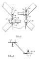
- a space frame comprises a plurality of chord members 1 of a chord structure which, in use, is uppermost relative to a surface over which the space frame extends, and a plurality of chord members 2 of a chord structure which is, in use, lower than the uppermost chord structure relative to the surface.
- a plurality of struts 3 spaces apart and connects together the chord structures.
- chord members 1 in the uppermost chord structure are fastened together in side by side relationship to form chords 40.
- chord members 2 in the lower chord structure are similarly fastened to form chords 41.
- chords 40 in the uppermost chord structure are spaced apart from one another by the same distance as the spacing between adjacent chords 41 in the lower chord structure. Furthermore the chords 40, 41 in both of the chord structures extend parallel with one another.
- chord member 1, 2 in either chord structure is connected to one adjacent chord only in the other chord structure by the struts 3. Moreover the chords 40 in the uppermost chord structure are laterally offset from the chords 41 in the lower chord structure so as to be disposed midway therebetween.
- the space frame is comprised of a number of prefabricated assembly sub-units which are transported to the site of use in an already constructed form.
- Each prefabricated assembly comprises two chord members 12 which are spaced apart and connected together by the struts 3 as shown in Figure 1.
- Such a prefabricated assembly may readily be juxtaposed with another prefabricated assembly in a manner such that the assemblies may be secured together to provide a composite of two such assemblies which can then be juxtaposed with an secured to a further assembly or assemblies.
- chord members 1, 2 in the embodiment of the space frame shown in Figures 1 to 5 comprises a channel section member having first and second parallel limbs 5, 6 which are spaced apart and connected together by a web 4.
- the struts 3 comprise a member having a straight tubular middle portion 7 and flattened end portions 8 which extend substantially parallel and in opposite directions to one another away from the middle portion. This is best seen in Figure 4.
- Each of the end portions 8 of the struts 3 has an aperture 9 which extends therethrough and in which a shank 20 of a bolt 21 may be received.
- chord members 1, 2 provides, at longitudinally spaced positions on the webs 4 thereof apertures 10 which extend through the webs 4 and which ore capable of receiving the shank 20 of a bolt 21.
- the apertures 10 are provided in pairs on the web 4, each pair of apertures 10 being closely spaced together and being provided at equally spaced positions longitudinally of the web. Such is the arrangement of the apertures 10 on the webs 4 of a chord member 1 relative to the positions of the apertures 10 in the webs 4 of the chord members 2 that in the constructed space frame the apertures in the webs 4 of the chord members 1 are intermediate the positions of the apertures 10 in the webs 4 of the chord members 2. Consequently the struts 3 extend obliquely between adjacent chord members in the uppermost and lower chord structures.
- pairs of chord members 1 which comprise a chord 40 in the uppermost chord structure are fastened to one another by means of a bolt 21 which passes through aligned apertures 10 in the webs 4 of the chord members 1 and in like manner pairs of chord members 2 in the other chord structure 41 are also fastened together by bolts.
- the struts 3 also are connected to the chord members 1, 2 by means of the bolts 21 and by means of reinforcing plates 22 which are interposed between heads 23 of the bolts and each end portion 8 of the struts 3 such that each end portion 8 of each strut 3 is interposed between a chord member 1, 2 and reinforcing plate 22.
- the reinforcing plates 22 comprise plates which each provide two holes 24 through which may be received the shanks 20 of the bolts 21. In this manner each reinforcing plate covers two apertures 10 in the web 4 of a chord member 1, 2 and serves to cover the end portions of two struts 3 where they are connected to the chord member in a manner such that the end portions 8 of the struts 3 do not overlap one another.
- FIGs 4 and 5 show a detail of two prefabricated assemblies immediately prior to securing the assemblies together.
- each pair of apertures 10 in the webs 4 of two juxtaposed chord members has two struts 3 connected thereto, one strut 3 at each aperture 10.
- the struts 3 are interposed in each case between a reinforcing plate 22 and the web 4.
- One of the struts in each pair is connected to the chord member by means of a bolt 21 and nut 21 a whilst the other is held in place between the reinforcing plate 22 and the web 4 by means of a plug 35 which extends through each of one of the apertures 10, the hole in the end portion 8 of the strut 3 and the aperture 24 in the reinforcing plate.
- each bolt 21 extending through one of the chord members is aligned with a plug 35 in the other.
- chord members may be fastened to one another more rapidly since there are fewer nuts to be undone from bolts and, moreover the chord members can be more closely aligned prior to fastening them together so that there is less chance of the reinforcing plates, struts and webs becoming misaligned during insertion of the shanks 20 into the, now vacant aligned holes and apertures.
- plugs 35 may be pushed out of their places by the shanks 20 of the bolts 21 as the chord members are brought together.
- the space frame according to the invention further comprises elongate upper 30 and lower 31 bracing members, the upper bracing members 30 being secured to and above the chords of the uppermost chord structure and the lower bracing members 31 being secured to and below the chords of the lower chord structure, the bracing members 30, 31 extending transversely to the chords and being laterally offset from one another.
- the bracing members 30, 31 are secured to the chords at positions along the length of the chords at which the apertures 10 are provided in the webs 4 thereof. In this way the bracing members 30, 31 cross the chords at positions at which the struts 3 are connected to the chord member 1, 2 in each chord structure.
- Each bracing member 30, 31 is secured to at least two of the chords in the respective chord structure to which that bracing member is secured.
- Structures of various different shapes and sub-unit shapes may be constructed from prefabricated assemblies of the kind described and it will be understood that individual integers of the space frame may be of alternative constructions to those described without departing from the spirit or scope of the invention.
- chord members 1, 2 could be of other shapes instead of channel shaped and Figure 6 shows part of a space frame in which the chord members 1, 2 are angle section members.
- Figure 6 shows an alternative embodiment of the invention in which fasteners are used to fasten together the chord members 1, 2 and separate connectors connect the struts 3 to the chord members 1, 2.
- separate means for connecting the struts to the chords and for fastening together the chord members 1, 2 may alternatively be provided in a space frame structure which provides chord members of channel section.
- the strut 3 is shown to be connected to a flange web 50 of the chord member which is perpendicular to the web 45 thereof, the struts 3 could be connected to and between the chord members 1, 2 by being connected to the webs 45 instead.
- struts 3 could be connected to these webs 45 at positions other than the positions of apertures in the webs 45 by which pairs of chord members in a given chord structure could be fastened together. Other apertures than these could be provided in the web 45 for connecting the struts 3 thereto.
- Figure 7 shows part of a still further embodiment of the invention in which the chord members 1, 2 each comprise channel section elongate members in which a first side web 60 is provided which is inclined relative to both an intermediate web 65 and to a second side web 70 thereof.
- the struts 3 need not possess end portions which are angled relative to a middle portion thereof but the resulting space frame still comprises chords in upper and lower chord structures which are laterally offset from one another.
- chord members are channel shaped or angle shaped or of any other shape separate or the same means may be used to fasten the chord members together to comprise chords and to connect the struts to the chords.
- Struts having an alternative construction or configuration to those described may be used if desired.
- bracing members may be secured to the chords in the respective chord structures by any suitable means such as by bolts or by welding.
- FIG. 8 another embodiment of a space frame according to the invention is shown which comprises chord members 1, 2 spaced apart and connected together by a plurality of struts 3.
- the struts 3 connect with the chord members 1, 2 by means of connectors 100 which comprise a plurality of plates 101, 102 which are connected together to form an integral whole and which are angled relative to one another so as to sit within an angle of a chord member 1, 2 and present the plates 101 at angles to one another and to sides 200, 201 of the chord members 1, 2 which provide the angle.
- the plates 102 each lie flat or substantially flat against the sides 200,201 of the chord members 1, 2 which form the angle and they provide apertures 103 which can be aligned with apertures provided in the chord members 1, 2 to permit of securing the plates 102 to the sides 200, 201 of the chord members 1, 2 by means of a bolt or similar fastener passed through the thus aligned apertures.
- chord members 1, 2 may also be used to fasten together chord members 1, 2 in back-to-back fashion and this is illustrated by a single bolt 104 in Figure 9.
- FIG. 12 shows an end of a strut 3 which has an insert 106 therein.
- the insert 106 is secured in the open end of the strut 3 by provision of an annular recess 110 in the insert.
- the wall of strut 3 is, during securement of the insert 110 therein, pressed so as to protrude into the recess and hold it against movement within the hollow interior of the strut.
- a protruding lip 111 of the strut 3 and is turned inwards further to secure the insert against displacement from the end of the strut.
- insert 106 could be secured to the struts by some means other than that described above, for example by the method set out in our prior patent 2169678. Moreover the securement could be releasable rather than permanent.
- the insert 106 includes a threaded bore 107 in which may be received a bolt which has been passed through an aperture of 105 in a plate 101 of a connector 100. This is illustrated in Figure 13.
- Figure 11 shows an alternative arrangement of the chord members 1, 2 in which one of each pair of chord members which lie back-to-back and are connected together comprise sides 300, 301 which form an angle and inwardly turned flanges 303, 304, each one of these providing, at its extremity a lip 110.
- the other of each pair of chord members which lie back-to-back also comprises sides which form an angle, one of the sides providing a flange 109 which is inwardly turned and the other of the sides providing an outwardly turned flange 108 which provides, at its extremity, a lip 111.
- the pairs of chord members, when juxtaposed for connection together are arranged such that the flange 108 and lip 111 overlie the flange 109 and lip 110 of an adjacent chord member. This assists in alignment of the chord members prior to and after connection together.
- chord members could be applied to the embodiment of the space frame which is shown in Figure 6 or to the embodiment of the space frame which is shown in Figure 7.
Landscapes
- Engineering & Computer Science (AREA)
- Architecture (AREA)
- Civil Engineering (AREA)
- Structural Engineering (AREA)
- Physics & Mathematics (AREA)
- Electromagnetism (AREA)
- Joining Of Building Structures In Genera (AREA)
Applications Claiming Priority (2)
| Application Number | Priority Date | Filing Date | Title |
|---|---|---|---|
| GB8922637 | 1989-10-07 | ||
| GB898922637A GB8922637D0 (en) | 1989-10-07 | 1989-10-07 | Space frame |
Publications (2)
| Publication Number | Publication Date |
|---|---|
| EP0422875A2 true EP0422875A2 (de) | 1991-04-17 |
| EP0422875A3 EP0422875A3 (en) | 1991-09-11 |
Family
ID=10664239
Family Applications (1)
| Application Number | Title | Priority Date | Filing Date |
|---|---|---|---|
| EP19900311011 Ceased EP0422875A3 (en) | 1989-10-07 | 1990-10-08 | Space frame |
Country Status (4)
| Country | Link |
|---|---|
| EP (1) | EP0422875A3 (de) |
| GB (2) | GB8922637D0 (de) |
| IE (1) | IE903570A1 (de) |
| PT (1) | PT95523A (de) |
Cited By (4)
| Publication number | Priority date | Publication date | Assignee | Title |
|---|---|---|---|---|
| EP1577457A1 (de) * | 2004-03-18 | 2005-09-21 | Giuseppe Suraci | Metalgitterträger für Gebäude und Bauweise unter dessen Verwendung |
| CN111236266A (zh) * | 2020-03-24 | 2020-06-05 | 中铁第四勘察设计院集团有限公司 | 支撑构件、基坑支护系统以及地铁车站的施工方法 |
| CN114072621A (zh) * | 2019-05-09 | 2022-02-18 | 太阳动力学有限责任公司 | 用于太阳能收集器的结构和技术 |
| WO2023142508A1 (zh) * | 2022-01-27 | 2023-08-03 | 湖南三一塔式起重机械有限公司 | 塔头和塔式起重机 |
Families Citing this family (1)
| Publication number | Priority date | Publication date | Assignee | Title |
|---|---|---|---|---|
| GB2285640A (en) * | 1994-01-13 | 1995-07-19 | Space Decks | Space frame system |
Family Cites Families (8)
| Publication number | Priority date | Publication date | Assignee | Title |
|---|---|---|---|---|
| DK104494C (da) * | 1963-12-20 | 1966-05-23 | Gram Brdr As | Fremgangsmåde ved udtagning af frosne formlegemer fra en fryseform samt apparat til udøvelse af fremgangsmåden. |
| US3477189A (en) * | 1967-02-20 | 1969-11-11 | Anthes Imperial Ltd | Load supporting structure |
| US3744206A (en) * | 1971-05-27 | 1973-07-10 | S Nelson | Heavy duty space frame four-way space frame |
| US3882653A (en) * | 1971-06-30 | 1975-05-13 | C O Inc | Truss construction |
| US4178736A (en) * | 1976-02-05 | 1979-12-18 | Salas Frank D | Housing module and space frame |
| GB2044830A (en) * | 1979-03-24 | 1980-10-22 | Frazer & Sons Ltd R | Latticed constructions |
| US5003748A (en) * | 1987-06-19 | 1991-04-02 | Supertruss Pty. Ltd. | Metal frame structure |
| US4821480A (en) * | 1988-06-01 | 1989-04-18 | Butler Manufacturing Company | Adjustable sidewall connection for roof panel support joists |
-
1989
- 1989-10-07 GB GB898922637A patent/GB8922637D0/en active Pending
-
1990
- 1990-10-04 PT PT9552390A patent/PT95523A/pt not_active Application Discontinuation
- 1990-10-04 GB GB9021604A patent/GB2236548B/en not_active Expired - Lifetime
- 1990-10-05 IE IE357090A patent/IE903570A1/en unknown
- 1990-10-08 EP EP19900311011 patent/EP0422875A3/en not_active Ceased
Cited By (6)
| Publication number | Priority date | Publication date | Assignee | Title |
|---|---|---|---|---|
| EP1577457A1 (de) * | 2004-03-18 | 2005-09-21 | Giuseppe Suraci | Metalgitterträger für Gebäude und Bauweise unter dessen Verwendung |
| CN114072621A (zh) * | 2019-05-09 | 2022-02-18 | 太阳动力学有限责任公司 | 用于太阳能收集器的结构和技术 |
| CN114072621B (zh) * | 2019-05-09 | 2024-01-30 | 太阳动力学有限责任公司 | 用于太阳能收集器的结构和技术 |
| US12123626B2 (en) | 2019-05-09 | 2024-10-22 | Solar Dynamics, Llc | Structures and techniques for solar collectors |
| CN111236266A (zh) * | 2020-03-24 | 2020-06-05 | 中铁第四勘察设计院集团有限公司 | 支撑构件、基坑支护系统以及地铁车站的施工方法 |
| WO2023142508A1 (zh) * | 2022-01-27 | 2023-08-03 | 湖南三一塔式起重机械有限公司 | 塔头和塔式起重机 |
Also Published As
| Publication number | Publication date |
|---|---|
| PT95523A (pt) | 1992-06-30 |
| GB2236548A (en) | 1991-04-10 |
| EP0422875A3 (en) | 1991-09-11 |
| IE903570A1 (en) | 1991-04-10 |
| GB9021604D0 (en) | 1990-11-21 |
| GB8922637D0 (en) | 1989-11-22 |
| GB2236548B (en) | 1994-05-11 |
Similar Documents
| Publication | Publication Date | Title |
|---|---|---|
| US4897979A (en) | Multiple wood truss connection | |
| DE2425279A1 (de) | Verbindungsknoten fuer ein raeumliches fachwerksystem | |
| US4965903A (en) | Modular bridge | |
| US7347030B2 (en) | Modular truss system with a nesting storage configuration | |
| US5403110A (en) | Square T clamp assembly for elongate members | |
| DE60119264T2 (de) | Momentwiderstehende Bandverbindung | |
| CA1205273A (en) | Expandable connector and method of using same to form curved structural framework | |
| US4890436A (en) | Multiple wood truss connection | |
| US5816011A (en) | Joint fitting for unit building | |
| US6299378B1 (en) | Connector plate and method of assembly | |
| DD298299A5 (de) | Wandkonstruktionssystem | |
| WO1993024712A1 (en) | Building frame | |
| US4054392A (en) | Releasable mechanical joints | |
| DE69924538T2 (de) | Verfahren und Vorrichtung zum Befestigen eines Trägers | |
| CH656438A5 (de) | Einrichtung zur bildung eines geruests. | |
| EP0422875A2 (de) | Raumfachwerk | |
| DE20110501U1 (de) | Aufblasbares Zelt | |
| JP2003502534A (ja) | 汎用構造部材 | |
| DE69326483T2 (de) | Konstruktionsverbindung | |
| EP0044282A2 (de) | Regaleinrichtung aus Metall mit mehreren Verbindungen sowie Elemente zur Bildung dieser Regaleinrichtung | |
| DE4033704A1 (de) | Vorrichtung zum sichern von gestapelten transportbehaeltern | |
| DE4422629C1 (de) | Vorrichtung zur Verbindung von Bauwerksteilen zur Bildung von Deckenkonstruktionen | |
| GB1602921A (en) | Elongate structural element | |
| DE3304843C1 (de) | Als Gittertraeger ausgebildeter Kalottenfussbalken | |
| DE2941718A1 (de) | Verbindungsvorrichtung fuer gitterstrukturen |
Legal Events
| Date | Code | Title | Description |
|---|---|---|---|
| PUAI | Public reference made under article 153(3) epc to a published international application that has entered the european phase |
Free format text: ORIGINAL CODE: 0009012 |
|
| AK | Designated contracting states |
Kind code of ref document: A2 Designated state(s): AT BE CH DE DK ES FR GB GR IT LI LU NL SE |
|
| PUAL | Search report despatched |
Free format text: ORIGINAL CODE: 0009013 |
|
| AK | Designated contracting states |
Kind code of ref document: A3 Designated state(s): AT BE CH DE DK ES FR GB GR IT LI LU NL SE |
|
| 17P | Request for examination filed |
Effective date: 19910821 |
|
| 17Q | First examination report despatched |
Effective date: 19911106 |
|
| RAP1 | Party data changed (applicant data changed or rights of an application transferred) |
Owner name: WARD BUILDING SYSTEMS LIMITED |
|
| STAA | Information on the status of an ep patent application or granted ep patent |
Free format text: STATUS: THE APPLICATION HAS BEEN REFUSED |
|
| 18R | Application refused |
Effective date: 19950610 |