EP0422890A2 - Dispositif pour mesurer la force avec réglage de mise à zéro - Google Patents
Dispositif pour mesurer la force avec réglage de mise à zéro Download PDFInfo
- Publication number
- EP0422890A2 EP0422890A2 EP90311045A EP90311045A EP0422890A2 EP 0422890 A2 EP0422890 A2 EP 0422890A2 EP 90311045 A EP90311045 A EP 90311045A EP 90311045 A EP90311045 A EP 90311045A EP 0422890 A2 EP0422890 A2 EP 0422890A2
- Authority
- EP
- European Patent Office
- Prior art keywords
- bridge
- strain gauge
- resistors
- pair
- load cell
- Prior art date
- Legal status (The legal status is an assumption and is not a legal conclusion. Google has not performed a legal analysis and makes no representation as to the accuracy of the status listed.)
- Ceased
Links
Images

Classifications
-
- G—PHYSICS
- G01—MEASURING; TESTING
- G01L—MEASURING FORCE, STRESS, TORQUE, WORK, MECHANICAL POWER, MECHANICAL EFFICIENCY, OR FLUID PRESSURE
- G01L25/00—Testing or calibrating of apparatus for measuring force, torque, work, mechanical power, or mechanical efficiency
-
- G—PHYSICS
- G01—MEASURING; TESTING
- G01L—MEASURING FORCE, STRESS, TORQUE, WORK, MECHANICAL POWER, MECHANICAL EFFICIENCY, OR FLUID PRESSURE
- G01L1/00—Measuring force or stress, in general
- G01L1/20—Measuring force or stress, in general by measuring variations in ohmic resistance of solid materials or of electrically-conductive fluids; by making use of electrokinetic cells, i.e. liquid-containing cells wherein an electrical potential is produced or varied upon the application of stress
- G01L1/22—Measuring force or stress, in general by measuring variations in ohmic resistance of solid materials or of electrically-conductive fluids; by making use of electrokinetic cells, i.e. liquid-containing cells wherein an electrical potential is produced or varied upon the application of stress using resistance strain gauges
- G01L1/225—Measuring circuits therefor
- G01L1/2262—Measuring circuits therefor involving simple electrical bridges
-
- G—PHYSICS
- G01—MEASURING; TESTING
- G01L—MEASURING FORCE, STRESS, TORQUE, WORK, MECHANICAL POWER, MECHANICAL EFFICIENCY, OR FLUID PRESSURE
- G01L1/00—Measuring force or stress, in general
- G01L1/20—Measuring force or stress, in general by measuring variations in ohmic resistance of solid materials or of electrically-conductive fluids; by making use of electrokinetic cells, i.e. liquid-containing cells wherein an electrical potential is produced or varied upon the application of stress
- G01L1/22—Measuring force or stress, in general by measuring variations in ohmic resistance of solid materials or of electrically-conductive fluids; by making use of electrokinetic cells, i.e. liquid-containing cells wherein an electrical potential is produced or varied upon the application of stress using resistance strain gauges
- G01L1/2268—Arrangements for correcting or for compensating unwanted effects
Definitions
- the present invention relates to strain gage load cells for precision measurement of weights and forces, especially load cells of the Planar Gaged Plate design, and specifically to improvements in the zero adjustments for such load cells.
- the present invention is an improvement of the known method for zero adjustment using resistors outside the bridge arms, which can be used even in load cell arrangements where the sensitivity of individual strain gage elements must maintain equal sensitivity.
- a load cell apparatus or arrangement with a strain gage bridge having four individual strain gage means and a pair of temperature compensation resistors connected between each end of a first diagonal of the strain gage bridge, a power supply for the bridge, and a measuring circuit being connected across a second diagonal in said strain gage bridge, comprises a first pair of substantially equal resistors connected across one pair of opposing arms of the strain gage bridge so that the signal at zero load on the load cell arrangement is rendered independent of temperature, and a second pair of substantially equal resistors connected between the two terminals of the power supply to the strain gage bridge and the two ends of the second diagonal of the strain gage bridge so the signal at zero load on the load cell arrangement is balanced to be zero.
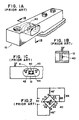
- FIGS. 1A, 1B and 1C show a shear beam load cell 10 in which a strain gage assembly 40 is mounted on a recessed surface 12 subject to shear stress.
- the strain gage assembly 40 contains four individual strain gage elements 41, 42, 43 and 44 on a common base that is bonded to the surface 12.
- a pair of temperature sensitive resistors 45′, 45 ⁇ are also bonded to the surface 12.
- the individual strain gage elements 41, 42, 43, 44 are arranged at a 45 degree angle to an axis of the load cell 10, as illustrated, so that a first pair 41, 44 are subject to tensile strain and a second pair 42, 43 are subject to compressive strain when a force F acts on the load cell.
- FIG. 2 shows how the four strain gages 41, 42, 43, 44, which are made of material with very low temperature coefficient of resistance, are connected together in a bridge arrangement 40.
- a first bridge diagonal (A-B) is connected to a source of power 50 in series with the temperature dependent resistors 45′, 45 ⁇ , and a measuring device 51 is connected to a second bridge diagonal (C-D).
- the two strain gages 41, 44 subject to tensile strain are connected in opposing bridge arms, as are the two gages 42, 43 subject to compressive strain. Accordingly, the second bridge diagonal (C-D) will provide a signal, increasing linearly with the force F acting on the load cell, to a measuring device or circuit 51.
- the known purpose of the temperature dependent resistors 45′, 45 ⁇ is to compensate for the temperature variation of the modulus of elasticity of the sensing element of the load cell and the gage factor of the strain gages.
- the modulus of elasticity decreases when the temperature is raised, so the strains sensed by the strain gages at constant load F increase with increasing temperature in the load cell, and the gage factor of the strain gages increase with increasing temperature. Both effects would thus cause the signal to the measuring device 51 to increase with the temperature of the load cell if the strain gage bridge were supplied with a constant voltage.
- the effect of the temperature dependent resistors 45′, 45 ⁇ is to reduce the supply voltage to the strain gage bridge when the temperature of the load cell increases, so that the signal supplied to the measuring device 51 at fixed bridge unbalance decreases with increasing temperature.
- Resistors 45′, 45 ⁇ are usually nickel or Balco resistors, often shunted by temperature independent resistors for optimization of the temperature compensation.
- the four strain gages 41, 42, 43, 44 all have the same nominal resistance value, usually a standard value of 350 Ohm or 1,000 Ohm.
- the resistance tolerance is, however, in the order of 0.2%, so the bridge will initially not be balanced when there is no load F on the load cell. This zero signal can be cancelled either by means of a shunt resistor 65 across one of the bridge arms, or by means of a resistor 66 connecting a corner (D) of the strain gage bridge with one terminal of the power supply 50.
- resistors 65, 66 will compensate for an output signal from the bridge 40 at zero load on the load cell, but their effects on the bridge are quite different. The difference becomes apparent when the load cell is subjected to temperature change while mechanically unloaded. In its initial stage, without resistors 65, 66, the output signal from the second bridge diagonal (C-D) will usually not be zero, and the signal will change with the temperature on the load cell. Resistor 66 adds a constant voltage counteracting the no load signal from the second bridge diagonal, so it can balance the bridge at any temperature, but the counteracting voltage does not vary with temperature. Accordingly, resistor 66 does not change the variation with temperature of the zero signal. Resistor 65, on the other hand, causes an imbalance in the strain gage bridge, so it affects the temperature dependence of the zero signal as well as the amount of zero signal.
- resistor 65 would cancel both the zero signal and the change in zero signal with temperature. In practice, however, this is not the case.
- the residual temperature dependence which can be either positive or negative, is caused by small differences between individual strain gages in the temperature coefficient of the resistance and the linear expansion coefficient of the gage material, as well as by the temperature dependence of the resistance in copper wires used to interconnect the strain gages.
- a known method for adjustment of both zero voltage and the temperature effect on the zero voltage in a strain gage bridge utilizes the different effects of resistors 65 and 66, by first selecting a resistor 65 that will cancel the temperature dependence of the output signal from the bridge 40, irrespective of the amount of the remaining zero signal, and then adding a resistor 66 that will cancel the remaining zero signal.
- the resistance values for resistors 65 and 66 can be determined by trial and error, or by calculations based on the measured zero signal at two different temperatures on the load cell and data for the strain gages and the temperature compensating resistors 45′, 45 ⁇ .
- the zero adjustment resistors 65 and 66 are shown connected respectively across the bridge arm with gage 43 and to the corner D of the bridge 40. However, it should be understood that resistor 65 could instead be connected across the bridge arm with gage 41, and resistor 66 could be connected to either corner C or corner D of the bridge, depending on the polarity of the corrections required to counteract the initial bridge unbalance and the polarity of the residual temperature effects on zero balance.
- FIG. 3 shows a Planar Gaged Plate load cell 10 with four individual strain gages 41, 42, 43, 44 on separate bending elements 12 ⁇ , 12′ of bending member 12, and 13 ⁇ and 13′ of bending member 13.
- a support plate 14 is bolted to a base (not shown), and a loading surface (not shown) covering the entire load cell arrangement 10 is bolted to a receiving plate 15.
- a weight such as a letter or package
- the equalization of the corner sensitivities is achieved, according to the copending Lockery application referenced above, by shunting a bridge half containing the right bridge half (43, 44) or left bridge half (41,42) by a pair of equal resistors 61′, 61 ⁇ to eliminate any sensitivity difference between the right and the left side of the device, and by shunting the front bridge half (42, 44) or back bridge half (41, 43) by a pair of equal resistors 62′, 62 ⁇ to eliminate any front to back difference in sensitivity.
- resistors 65 and 66 would act as shunts to individual strain gages (41, 43). Resistors 65 and 66 would accordingly change the sensitivity of the shunted bridge arms, so the load cell 10 would become sensitive to the location of the center of gravity of the load F.
- the resistance value of resistors 65 and 66 used in the zero adjustment method discussed in connection with FIG. 2 are typically 0.1 Megohm or larger for a bridge with 350 ohm strain gages, so the shunting effect on the sensitivity is small, but not negligible. In the load cell shown in FIGS. 1A, 1B and 1C this was not a problem, because all the four strain gages in this load cell sense a common shear strain, so the sensitivity of individual gages is not critical.
- Zero adjustment of the strain gage bridge in FIG. 4 with sensitivity equalization by shunting of half bridges (43, 44 and 42, 44) by resistor pairs (61′, 61 ⁇ and 62′, 62 ⁇ ) can, however be made according to the invention without upsetting the sensitivity adjustment.
- the shunting effect of resistor 65′ affects the sensitivity of both the right hand half bridge (43, 44) and the top half bridge (41, 43) by the same amount as the shunting effect of the equally large resistor 65 ⁇ affects both the left hand half bridge (41, 42) and the bottom half bridge (42, 44). Therefore, the two effects balance each other in both sets of half bridges. In the same way the shunting effects of the two equal resistors 66′ and 66 ⁇ balance each other. The relative sensitivities of all the bridge arms thus remain unchanged after the zero adjustment.
- R45 T Resistance in each of resistors 45′ and 45 ⁇ at temperature T.
- R65′, R65 ⁇ , R66′, R66 ⁇ Resistances in resistors 65′, 65 ⁇ , 66′ and 66 ⁇ respectively.
- RB AB and RB CD for resistances measured over bridge diagonals A-B and C-D respectively.
- UB T Voltage over bridge diagonal A-B at temperature T.
- U0CD T Voltage between bridge corners C and D at open circuit at temperature T.
- ISCD T Current in short circuit between bridge corners C - D at temperature T.
- the temperature coefficients for the strain gages and the metal film resistors are so small compared to the temperature coefficient for the nickel resistors that they can be set to zero in the following calculations without significant errors.
- the actual resistors 65′, 65 ⁇ and 66′, 66 ⁇ will normally be picked from a series of standard resistors, such as a R96 series, and that the individual resistance values deviage from a nominal value by a certain tolerance.
- the resistors in a pair actually used in the circuit will accordingly not have exactly equal resistance values, nor will the resistance values be exactly equal to the calculated values, but the errors are usually negligible.
- formulas (VII) and (X) that it is actually the sum of the resistances in each pair that determine the accuracy of the bridge balance. Therefore, it is possible to improve the accuracy of the compensation by selecting the two resistors in a pair from adjacent R96 values instead of from the same R96 value. Such a small deviation will not affect the sensitivity equalization of the individual strain gage elements to any significant degree.
- resistors 65′ and 65 ⁇ shown in FIG. 4 are valid for the specific data assumed in the example above, and that they may be across bridge arms 41 and 44 in other cases. It should also be clear that resistors 66′ and 66 ⁇ should be connected respectively to bridge corners C and D under the conditions assumed in the example above, but they may have to be connected to the opposite bridge corners (D and C respectively) if the conditions are different.
- the condition defined as no load on the load cell 10 may include the case of a constant tare load acting on the load cell.
- the zero adjustment works equally well in such a case, provided only that the tare load is always present during all tests, especially during the tests with different temperatures on the load cell.
- the invention is not limited to the type of load cell used as examples herein. It can be used for zero balancing in all kinds of strain gage load cells, including such that do not require equal sensitivity in individual gages. However, the invention's advantages are most apparent in sensitivity equalized load cell arrangements.
Landscapes
- Physics & Mathematics (AREA)
- General Physics & Mathematics (AREA)
- Measurement Of Force In General (AREA)
- Measurement Of Length, Angles, Or The Like Using Electric Or Magnetic Means (AREA)
Applications Claiming Priority (2)
| Application Number | Priority Date | Filing Date | Title |
|---|---|---|---|
| US07/419,391 US4958526A (en) | 1989-10-10 | 1989-10-10 | Force measuring device with zero adjustment |
| US419391 | 1999-10-15 |
Publications (2)
| Publication Number | Publication Date |
|---|---|
| EP0422890A2 true EP0422890A2 (fr) | 1991-04-17 |
| EP0422890A3 EP0422890A3 (en) | 1991-09-11 |
Family
ID=23662062
Family Applications (1)
| Application Number | Title | Priority Date | Filing Date |
|---|---|---|---|
| EP19900311045 Ceased EP0422890A3 (en) | 1989-10-10 | 1990-10-09 | Force measuring device with zero adjustment |
Country Status (2)
| Country | Link |
|---|---|
| US (1) | US4958526A (fr) |
| EP (1) | EP0422890A3 (fr) |
Cited By (2)
| Publication number | Priority date | Publication date | Assignee | Title |
|---|---|---|---|---|
| DE4429222A1 (de) * | 1993-08-24 | 1995-03-09 | Nsk Ltd | Aufprallsensor |
| CN103983400A (zh) * | 2014-05-14 | 2014-08-13 | 西安热工研究院有限公司 | 一种应力应变仪表万能检测装置及方法 |
Families Citing this family (19)
| Publication number | Priority date | Publication date | Assignee | Title |
|---|---|---|---|---|
| US5306873A (en) * | 1990-09-26 | 1994-04-26 | Ishida Scales Mfg. Co., Ltd. | Load cell with strain gauges having low temperature dependent coefficient of resistance |
| US5086856A (en) * | 1990-11-20 | 1992-02-11 | Flintab Ab | Method and apparatus for weighing a wheel supported load |
| DE4125580A1 (de) * | 1991-08-02 | 1993-02-04 | Schenck Ag Carl | Vorrichtung zum messen von kraeften |
| NZ248606A (en) * | 1992-09-11 | 1995-07-26 | Arthur Kellenbach | Shear beam loadcell: lateral groove present between lower surface of mounting portion and lower surface of coplanar free strain sensing portion |
| DE4416442A1 (de) * | 1994-05-11 | 1995-11-16 | Hottinger Messtechnik Baldwin | Verfahren und Vorrichtung zum Abgleich eines Meßkörpers eines Meßwertaufnehmers |
| US5910645A (en) * | 1994-05-11 | 1999-06-08 | Hottinger Baldwin Messtechnik Gmbh | Method and apparatus for making load cells less sensitive to off-center load applications |
| US5886302A (en) * | 1995-02-08 | 1999-03-23 | Measurement Specialties, Inc. | Electrical weighing scale |
| US5837946A (en) * | 1995-06-16 | 1998-11-17 | Weigh-Tronix, Inc. | Force sensitive scale and dual load sensor cell for use therewith |
| DE19632709C1 (de) * | 1996-08-14 | 1998-01-08 | Sartorius Gmbh | Elektronische Waage mit Lenkerparallelführung und DMS-Ecklastsensor |
| US6147312A (en) * | 1998-10-05 | 2000-11-14 | Flintec Inc. | Strain gage bridge circuit with sensitivity equalization and method for sensitivity equalization |
| US6729187B1 (en) * | 1999-04-29 | 2004-05-04 | The Board Of Governors For Higher Education, State Of Rhode Island And Providence Plantations | Self-compensated ceramic strain gage for use at high temperatures |
| US6910392B2 (en) * | 2003-02-20 | 2005-06-28 | The Flintec Group, Ltd. | Bending beam load cell with torque sensitivity compensation |
| US7009118B2 (en) * | 2003-05-13 | 2006-03-07 | Dynamic Datum Llc | Vehicle load weighing system and load cells for such systems |
| US6888074B2 (en) * | 2003-06-10 | 2005-05-03 | The Flintec Group, Ltd. | Compression column load cell |
| US7342185B2 (en) * | 2003-06-10 | 2008-03-11 | The Flintec Group, Ltd. | Compression column load cell with compensation for off center loading errors |
| WO2008029648A1 (fr) * | 2006-09-05 | 2008-03-13 | Ishida Co., Ltd. | Module de cellules de charge, contrôleur de poids, et instrument de pesée électronique |
| CN110553786B (zh) * | 2019-10-11 | 2021-09-24 | 北京七星华创流量计有限公司 | 压力传感器的补偿方法和系统 |
| US12553782B2 (en) * | 2022-06-29 | 2026-02-17 | Subaru Corporation | Load cell and output adjustment method of load cell |
| USD1090305S1 (en) * | 2024-04-16 | 2025-08-26 | Feeney, Inc. | Cable tension gauge |
Family Cites Families (4)
| Publication number | Priority date | Publication date | Assignee | Title |
|---|---|---|---|---|
| US3576128A (en) * | 1969-03-13 | 1971-04-27 | Blh Electronics | Half bridge moment desensitization of parallelogram-type beams |
| US3968676A (en) * | 1975-03-24 | 1976-07-13 | Ormond Alfred N | Mechanical equalization of strain gauge sensitivity |
| US4380175A (en) * | 1981-06-12 | 1983-04-19 | Reliance Electric Company | Compensated load cell |
| US4556115A (en) * | 1983-06-17 | 1985-12-03 | Hottinger Baldwin Measurement, Inc. | Method and means for equalizing the measuring sensitivity of a plurality of strain gage transducers |
-
1989
- 1989-10-10 US US07/419,391 patent/US4958526A/en not_active Expired - Fee Related
-
1990
- 1990-10-09 EP EP19900311045 patent/EP0422890A3/en not_active Ceased
Cited By (3)
| Publication number | Priority date | Publication date | Assignee | Title |
|---|---|---|---|---|
| DE4429222A1 (de) * | 1993-08-24 | 1995-03-09 | Nsk Ltd | Aufprallsensor |
| CN103983400A (zh) * | 2014-05-14 | 2014-08-13 | 西安热工研究院有限公司 | 一种应力应变仪表万能检测装置及方法 |
| CN103983400B (zh) * | 2014-05-14 | 2016-03-02 | 西安热工研究院有限公司 | 一种应力应变仪表万能检测装置及方法 |
Also Published As
| Publication number | Publication date |
|---|---|
| EP0422890A3 (en) | 1991-09-11 |
| US4958526A (en) | 1990-09-25 |
Similar Documents
| Publication | Publication Date | Title |
|---|---|---|
| US4958526A (en) | Force measuring device with zero adjustment | |
| US4380175A (en) | Compensated load cell | |
| US4556115A (en) | Method and means for equalizing the measuring sensitivity of a plurality of strain gage transducers | |
| US3927560A (en) | Moment desensitization of load cells | |
| US5837946A (en) | Force sensitive scale and dual load sensor cell for use therewith | |
| US4979580A (en) | Force measuring device with sensitivity equalization | |
| JP3251081B2 (ja) | 計量装置 | |
| US6910392B2 (en) | Bending beam load cell with torque sensitivity compensation | |
| CN1122631A (zh) | 具有完整温度信号的应变仪传感器 | |
| JPS604417B2 (ja) | 歪ゲージ変換器 | |
| US4261195A (en) | Transducer bridge circuit arrangement and method | |
| EP0082698B1 (fr) | Circuit de compensation de température pour jauges de contrainte | |
| GB2201791A (en) | Transducer signal conditioner | |
| US4577709A (en) | Weighing scale with a load cell | |
| US4541496A (en) | Measurement circuit for load cell mass comparator | |
| US6147312A (en) | Strain gage bridge circuit with sensitivity equalization and method for sensitivity equalization | |
| USRE32631E (en) | Measurement circuit for load cell | |
| Dorsey | Homegrown strain-gage transducers: Simple compensation procedures can be used to correct errors in strain-gage transducer bridges | |
| US3034347A (en) | Strain gauge bridge circuit arrangement, particularly for load cells | |
| JPH0769232B2 (ja) | ロ−ドセルの温度補償方法及びその装置 | |
| US5369226A (en) | Load shift compensation for weighing apparatus | |
| JP3465946B2 (ja) | ロードセルの温度補償方法及びその装置 | |
| US5031463A (en) | Load cell output correction circuitry | |
| JPH0125425B2 (fr) | ||
| JP2000111425A (ja) | デジタルロードセルの温度補償装置 |
Legal Events
| Date | Code | Title | Description |
|---|---|---|---|
| PUAI | Public reference made under article 153(3) epc to a published international application that has entered the european phase |
Free format text: ORIGINAL CODE: 0009012 |
|
| AK | Designated contracting states |
Kind code of ref document: A2 Designated state(s): DE ES FR GB NL SE |
|
| PUAL | Search report despatched |
Free format text: ORIGINAL CODE: 0009013 |
|
| AK | Designated contracting states |
Kind code of ref document: A3 Designated state(s): DE ES FR GB NL SE |
|
| 17P | Request for examination filed |
Effective date: 19920311 |
|
| 17Q | First examination report despatched |
Effective date: 19930628 |
|
| STAA | Information on the status of an ep patent application or granted ep patent |
Free format text: STATUS: THE APPLICATION HAS BEEN REFUSED |
|
| 18R | Application refused |
Effective date: 19940220 |