EP0422934B1 - Fenêtre de sécurité effaçable - Google Patents
Fenêtre de sécurité effaçable Download PDFInfo
- Publication number
- EP0422934B1 EP0422934B1 EP90311142A EP90311142A EP0422934B1 EP 0422934 B1 EP0422934 B1 EP 0422934B1 EP 90311142 A EP90311142 A EP 90311142A EP 90311142 A EP90311142 A EP 90311142A EP 0422934 B1 EP0422934 B1 EP 0422934B1
- Authority
- EP
- European Patent Office
- Prior art keywords
- screen
- window
- frame
- socket
- assembly according
- Prior art date
- Legal status (The legal status is an assumption and is not a legal conclusion. Google has not performed a legal analysis and makes no representation as to the accuracy of the status listed.)
- Expired - Lifetime
Links
- 239000002184 metal Substances 0.000 claims abstract description 16
- 229910000831 Steel Inorganic materials 0.000 claims description 4
- 239000010959 steel Substances 0.000 claims description 4
- 230000007246 mechanism Effects 0.000 description 12
- 238000009434 installation Methods 0.000 description 5
- 230000000694 effects Effects 0.000 description 4
- 238000012423 maintenance Methods 0.000 description 4
- 230000008439 repair process Effects 0.000 description 3
- 230000004888 barrier function Effects 0.000 description 2
- 230000006835 compression Effects 0.000 description 2
- 238000007906 compression Methods 0.000 description 2
- 239000000463 material Substances 0.000 description 2
- 239000004033 plastic Substances 0.000 description 2
- 206010017472 Fumbling Diseases 0.000 description 1
- 241000238631 Hexapoda Species 0.000 description 1
- 229920004142 LEXAN™ Polymers 0.000 description 1
- 239000004418 Lexan Substances 0.000 description 1
- 230000000712 assembly Effects 0.000 description 1
- 238000000429 assembly Methods 0.000 description 1
- 230000008901 benefit Effects 0.000 description 1
- 230000015572 biosynthetic process Effects 0.000 description 1
- 238000004140 cleaning Methods 0.000 description 1
- 230000008878 coupling Effects 0.000 description 1
- 238000010168 coupling process Methods 0.000 description 1
- 238000005859 coupling reaction Methods 0.000 description 1
- 238000006073 displacement reaction Methods 0.000 description 1
- 238000007689 inspection Methods 0.000 description 1
- 235000000396 iron Nutrition 0.000 description 1
- 238000005461 lubrication Methods 0.000 description 1
- 230000004048 modification Effects 0.000 description 1
- 238000012986 modification Methods 0.000 description 1
- 230000003287 optical effect Effects 0.000 description 1
- 239000003973 paint Substances 0.000 description 1
- 238000010422 painting Methods 0.000 description 1
- 239000011148 porous material Substances 0.000 description 1
- 230000009467 reduction Effects 0.000 description 1
- 238000012216 screening Methods 0.000 description 1
- 239000000779 smoke Substances 0.000 description 1
- 229910001220 stainless steel Inorganic materials 0.000 description 1
- 239000010935 stainless steel Substances 0.000 description 1
- 239000000126 substance Substances 0.000 description 1
- 238000009423 ventilation Methods 0.000 description 1
Images


Classifications
-
- E—FIXED CONSTRUCTIONS
- E05—LOCKS; KEYS; WINDOW OR DOOR FITTINGS; SAFES
- E05C—BOLTS OR FASTENING DEVICES FOR WINGS, SPECIALLY FOR DOORS OR WINDOWS
- E05C19/00—Other devices specially designed for securing wings, e.g. with suction cups
- E05C19/006—Other devices specially designed for securing wings, e.g. with suction cups by displacement of the wing substantially in its own plane
-
- E—FIXED CONSTRUCTIONS
- E06—DOORS, WINDOWS, SHUTTERS, OR ROLLER BLINDS IN GENERAL; LADDERS
- E06B—FIXED OR MOVABLE CLOSURES FOR OPENINGS IN BUILDINGS, VEHICLES, FENCES OR LIKE ENCLOSURES IN GENERAL, e.g. DOORS, WINDOWS, BLINDS, GATES
- E06B9/00—Screening or protective devices for wall or similar openings, with or without operating or securing mechanisms; Closures of similar construction
- E06B9/02—Shutters, movable grilles, or other safety closing devices, e.g. against burglary
-
- E—FIXED CONSTRUCTIONS
- E06—DOORS, WINDOWS, SHUTTERS, OR ROLLER BLINDS IN GENERAL; LADDERS
- E06B—FIXED OR MOVABLE CLOSURES FOR OPENINGS IN BUILDINGS, VEHICLES, FENCES OR LIKE ENCLOSURES IN GENERAL, e.g. DOORS, WINDOWS, BLINDS, GATES
- E06B9/00—Screening or protective devices for wall or similar openings, with or without operating or securing mechanisms; Closures of similar construction
- E06B9/02—Shutters, movable grilles, or other safety closing devices, e.g. against burglary
- E06B9/04—Shutters, movable grilles, or other safety closing devices, e.g. against burglary of wing type, e.g. revolving or sliding
Definitions
- This invention relates generally to window guards to prevent unauthorized access to a building through its windows, and more particularly to a releasable window guard screen and frame assembly whose hinged metal screen may be swung out of the frame opening to permit exit from the building through the window.
- a guard formed by a framed mesh screen of heavy gauge wire, making it difficult for an intruder to cut the mesh.
- a wire mesh screen or one made of expanded metal not only prevents intruders from gaining access to the building through the guarded windows, but also serves to shield these windows against breakage.
- a permanently-installed window guard has a number of disadvantages, the primary drawback being that in the event of a fire or other emergency, it is not possible to leave the building through the guarded window. One must therefore find another way to escape, and this may not then be available.
- Another disadvantage of a framed wire mesh screen is that, in time, the screen may become loose or detached from its frame and hence cease to be effective.
- window guard design Another factor that must be taken into account in window guard design is the extent to which the screen cuts down the amount of light and ventilating air admitted therethrough, as well as the degree to which it reduces visibility. With heavy gauge and relatively thick wire mesh screens, there is a marked reduction in the amount of admitted light and air, and visibility is hindered by the thickness of the screen, particularly when looking through the mesh-guarded window at an oblique angle.
- window guards with releasable locking mechanisms which when unlatched permit the screen to be removed or to swing out, thereby permitting exit through the window in case of fire or other emergency.
- the ideal locking mechanism for a window guard is one which can be quickly unlatched without difficulty in the event of an emergency, but which when latched makes it very difficult to remove or to swing out the screen, and therefore affords a high degree of security.
- Prior art locking mechanisms for window guards are either relatively complicated and difficult to release quickly, or of a simple mechanical design that do not offer a high degree of security.
- window guard design One must also take into account in window guard design the need for repair and maintenance, for in time it may be necessary to replace the screen, to paint it or to lubricate the moving parts. With complicated window guards of the prior art type, these parts may be inaccessible or difficult to remove for purposes of maintenance and repair. Window guards are subjected to weathering, and conventional guards whose hinges and other key components are exposed, may as a result of rusting or painting, become difficult to open.
- the Pellicore patent 2,924,862 shows a window guard for school houses and other applications in which the guard fits within the window jamb.
- the window guard comprises a welded steel frame formed of a channel member which supports a woven wire mesh. Also provided is a releasable locking means so that the window guard can be opened quickly in the event of an emergency.
- the Levin patent 2,711,565 shows a window guard in the form of a main frame secured to the window opening, to which is hinged a closure frame supporting a wire mesh, locking means being provided.
- Kelly, 3,087,750. shows a window guard in which a framed woven-wire mesh screen is hinged to the side of a window, a lock being provided.
- the Fernandez patent 4,634,157 shows a window guard in which bars are supported by a rectangular frame to provide a guard which presents a prison-like appearance. Also prison-like is the bar assembly shown in patent 4,771,574 to Stephens, in which a grid formed by bars is held within a frame. Even more prison-like are the window grill of Warwick, 4,796,384 and the window guard of Hicks et al., 4,685,316.
- the patent to Merry, 4,677,789 shows a window guard in which a frame is secured to a window opening, to which is hinged an inner frame having a grate attached thereto.
- the Hatvany patent 4,566,222 discloses a one-piece window guard formed of a sheet of metal or plastic having cutouts therein to provide light and ventilation.
- the side margins of the sheet are rolled to form cylindrical rims, one receiving a hinge bolt and the other a locking bolt.
- the hinging rim and the locking rim are attached by angle irons to window wall studs.
- Hatvany points out that window guards provided with locking mechanisms which can be released from the inside of a building often include springs, flexible cables and other parts which, once installed, are inaccessible for inspection, cleaning, lubrication or replacement, and that should these mechanisms jam in an emergency situation, the consequences may be serious. Hatvany therefore provides a less complicated release mechanism for his window guard.
- Hatvany arrangement must be custom tailored to a window jamb of given dimensions in a complicated, costly, through-wall installation, and cannot be fitted into a jamb whose dimensions differ somewhat from the jamb for which it is designed.
- the main object of the invention is to provide an easily-releasable window guard assembly installable on the jamb of a building window to prevent unauthorized access to the building through the window, the same assembly being installable in window jambs whose dimensions differ somewhat from window-to-window.
- an object of this invention is to provide a window guard assembly whose screen is made of relatively thin metal perforated in a predetermined pattern to admit light and ventilating air, the pattern being aesthetically pleasing to render the installation attractive.
- an object of the invention is to provide a window guard assembly whose screen is hingedly-supported on a planar frame attachable by adjustable brackets to the wall of a window jamb, the brackets making it possible to mount the planar frame on jambs that from window-to-window vary somewhat in their dimensions, whereby the same assembly may be installed on all windows in the building without the need to custom fit the assembly.
- a significant feature of the invention is that no gap exists between the screen and the planar frame on which it is supported, thereby obviating the danger of the screen being pried open by a tool inserted in a gap.
- Another advantage of the invention is that the screen can easily be detached from the frame for purposes of maintenance or repair.
- an object of the invention is to provide an assembly of the above type having a single releasable latch to permit the screen to be swung out of the frame, which latch is accessible only from the interior of the building.
- a salient feature of the invention resides in its safety, for the quick-release latch on the unit expedites fast and sure egress in a dark, smoke-filled room or under other emergency conditions, and there is no search for keys or fumbling with a lock combination.
- Yet another object of the invention is to provide a window guard assembly that presents an attractive appearance and affords a high degree of security, yet can be manufactured at relatively low cost.
- the present invention seeks to provide a releasable window guard assembly installable on the jamb of a building window to prevent unauthorised access therethrough.
- the assembly comprises a metal screen whose margins define end and side branches which border a planar field, and a frame which supports the screen and defines an opening of a predetermined width and height, the frame being adapted to overlie or nest within the jamb of a window and being mountable thereto to prevent an intruder from gaining access through the window and to permit exit through the window when the screen is unlatched, the assembly being characterised in that the screen is of a height corresponding to the height of the opening defined by the frame and of a width greater than the width of said opening, and that the frame comprises a slideway socket which includes end and side legs formed on the rear surface of the frame for slidably receiving the screen, the screen being slidable within the socket and being hinged thereto by hinge pins extending through slots formed in the legs of the socket, whereby the screen is slidable between a security
- the releasable latch engages the other side branch of the screen and is accessible only from inside the building to lock the screen in its security mode position.
- the latch when released, permits the screen to be slid to the access mode position.
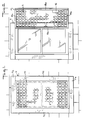
- a releasable window guard assembly has two main components: a metal screen identified generally by numeral 10, and a planar metal frame identified generally by numeral 11 behind whose rectangular opening the screen normally lies.
- a security mode as shown in Fig. 1, in which window 12 on or in whose jamb the assembly is installed is guarded
- an access mode as shown in Fig. 2 in which the window is unguarded.
- the security mode intrusion is prevented, while in the access mode, one may exit from the unguarded window in the event of a fire or other emergency.
- screen 10 In the security mode, screen 10, whose front surface is planar, lies against the rear surface of planar frame 11 and is blocked thereby, so that virtually no gap exists therebetween which would permit an intruder to insert a tool to pry open the screen.
- the planar frame lies flat against the exterior wall of the building, and since the front surface of the screen is virtually co-planar with the frame, the installed assembly is altogether free of bolts, ridges, or other protrusions, and therefore presents a clean, uncluttered appearance compatible with the architecture of the building.
- frame 11 may be dimensioned to nest within the window opening and to be flush with the facade of the building.
- the screen which is hinged to the frame, is provided with a latch to maintain it in its security mode.
- the rectangular opening of the frame has a height that matches that of the screen and a width somewhat smaller than that of the screen, so that it can only be swung out of the opening when angled with respect thereto. It is then possible in the access mode to swing out the screen and to open window 12 and exit therefrom. Also in this mode, one can clean the outside of window 12 and all parts of the assembly.
- frame 11 which is preferably formed of steel, is constituted by upper and lower end metal plates Fa and Fb and right and left side plates Fc and Fd which are welded together to form the frame behind whose rectangular opening lies screen 10 which in the security mode lies parallel to frame 11 and is blocked thereby.
- Attached to the inner surface of the frame plates are right-angle or L-shaped brackets 13, a spaced pair of brackets being provided for each plate.
- frame 11 may be formed of a single rectangular sheet of metal to which the brackets are attached.
- brackets 13 which are adjustable, serve to secure the frame to the corresponding end and side walls W of the jamb for window 12.
- One arm of each bracket is attached to a frame plate by a bolt 14 that passes through an elongated slot 15 in this arm.
- the other arm of each bracket is secured to a jamb wall W by a bolt 16 which passes through a slot in this arm.
- a suitable anchor may be wedged in a hole drilled in the wall, such as a masonry anchor, to threadably receive the mounting bolt. Because of slot 15, the position of each bracket 13 is adjustable within the slot limits relative to the related frame plate, the bracket offering two adjustment ranges by reason of the slots in the arms thereof.
- window jambs in a building are nominally identical in their dimensions, they actually vary somewhat from window to window. Also, some of the jambs may be out of square. But because brackets 13 are shiftable relative to the frame plates, the same assembly may be conformed to jambs that vary somewhat in their dimensions, thereby avoiding the need to custom-tailor the assemblies to the jambs.
- screen 10 is fabricated from a single sheet of high strength metal such as steel whose margins are folded in to define channel-shaped branches, each having a U-shaped cross section.
- the upper and lower end branches of screen 10 are identified as branches Ba and Bb, while the right and left side branches are identified as branches Bc and Bd. These branches are welded together at the corners of the screen to provide a screen, which even though fabricated of thin metal, is highly resistant to flexure.
- Screen branches Ba to Bd border a planar field 10F that is perforated to provide apertures A that admit light and ventilating air. But because the screen is thin, it does not markedly reduce visibility when one looks through the screen at an oblique angle. In contradistinction, in the case of a relatively thick mesh screen formed of woven wire, of expanded metal or similar material, one experiences a sharp loss in visibility, for at an oblique angle, a thick screen tends to block the view.
- Perforations A in planar field 10F are in a predetermined pattern dictated in good part by aesthetic considerations.
- the pattern may be such as to define an array of apertures divided into geometric zones by unapertured bands in a criss-cross or grid formation to produce casement window or other decorative effects to enhance the attractiveness of the assembly.
- the apertures are in staggered rows, each row being formed by a series of oblong apertures A in overlapping relation, so that the pattern is free of straight lines as in the grid-like pattern shown in Fig. 4. It has been found that the optical effect produced by the Fig. 9 pattern is such as to enhance visibility, in that the absence of straight vertical and horizontal lines under certain circumstances effectively erases the presence of the screen, or at least reduces the viewer's awareness of the screen.
- Fig. 9 The effect of the Fig. 9 pattern is comparable to that produced by a theatre scrim that is dropped over the front of a highly illuminated stage being viewed by an audience in a darkened theatre.
- the audience views the stage through the pores of the screen, they are not conscious of the screen but only of its effect in softening the image of the actors; for when the scrim is raised, the actors are then more sharply seen.
- FIG. 4 Screen 10, as best seen in Figs. 4, 5 and 6, is received within a slideway socket formed on the rear of frame 11.
- the socket is defined by upper and lower legs La and Lb, and right and left legs Lc and Ld welded or otherwise integrated with the corresponding frame plates Fa to Fd.
- Upper leg La as shown in Fig. 4, is provided with a turned-in flange La′, and lower leg Lb is provided with a similar flange Lb′.
- These flanges act as a barrier to prevent screen 10, which is hinged to the socket as well as being slidable therein, from swinging inwardly, the screen being permitted only to swing outwardly through the frame opening.
- these fixtures can be reversed for interior installation, so that the screen is then adapted to open inwardly, not outwardly. Where the objective is detention, not security, a guard having a security screen which pivots inwardly and is released from the exterior is then useful for this purpose.
- Right side leg Lc of the socket is flangeless, whereas left side leg Ld is channel-shaped to accommodate the correspondingly-shaped side branch Bd of screen 10.
- Mounted on left side leg Ld of the socket is a releasable latch 22 whose pin 22P enters a hole 17 in the corresponding side branch Bd of the screen to prevent sliding movement of the screen in the security mode of the assembly, as shown in Fig. 5.
- a shaped metal shield 18 Attached to the left side branch Bd of the screen at a position adjacent to latch 22 in side leg Ld is a shaped metal shield 18. This acts as a barrier to prevent an intruder outside the building from inserting a tool through the apertured screen to engage and release the latch. It also acts as a handle to facilitate sliding of the screen in the socket.
- the hand/shield is made from stainless steel and incorporates a 45 degree bend to deflect drill bits inserted by an intruder through the screen.
- screen 10 is hinged at the extremities of its right side branch Bc to the upper and lower legs La and Lb of the frame socket by hinge pins 19 and 20.
- the hinge pins pass through an elongated slot 21 in these legs.
- Fig. 5 shows hinge pin 20 at one end of slot 21 in the security mode of the assembly
- Fig. 6 shows pin 20 at the other end of slot 21 in the access mode in which the screen can now be angled with respect to the assembly and swung out on the hinge pins.
- the hinge pins are preferably spring-biased and in a form that can easily be disassembled should one wish to remove the screen from the frame socket for replacement or maintenance.
- the hinge pins may take the form of a threaded bolt 23 which receives a sleeve 24 surrounded by a helical spring 25, the spring being held between upper and lower washers 26 and 27.
- the hinge pin assembly is held together by a nut 28.
- the hinge pins may be of the cotter or any other type.
- latch 22 It is a simple matter to unlatch the screen, for all that is necessary is to pull out latch 22. Yet though simple, the latch is highly effective, for by pulling out the latch, one is not able to then swing out the screen, for to do so, one must first slide the screen to disengage its side branch Bd from the side leg Ld of the socket.
- a spring assembly may be provided to apply tension or compression to either the hinge side or the latch side of the screen as an opening assist mechanism to effect lateral displacement of the screen when the latch is released.
- This feature is useful for large and relatively heavy screens.
- a leaf-spring in the latch-side channel under compression or coil-springs on the hinge-side in tension will work to assist the operator in sliding the screen away from the latch until it is clear of the frame retainer and may then be swung open.
- a narrow space between the screen and the upper and lower legs of the retaining socket within which the screen is slidable is unavoidable.
- the hinge pins coupling these legs and the upper and lower branches of the socket extend through this space, and it would be possible with an appropriate tool for an intruder to insert this tool into this narrow space and saw through the hinge pins.
- the screen in its security mode position is latched, even if the hinge pins are cut, it would still be impossible to remove the screen from its confining socket, for to do so, one must first slide the screen, and this cannot be done without first releasing the latch which is not accessible to the intruder.
- a plastic tamper seal may be provided that goes through the secondary set of holes, but which can be pulled off when necessary.
- this mechanism can be of the "push” type or of the side-operating type. Because of the branched character of the screen, its channels may be used to accommodate a Lexan window to render it bullet proof, or a storm window, or an insect screening.
- the entire unit can be so oriented on installation as to permit the hinged screen to open either to the right or left, or up or down.
- the latch and handle are installed at the site at appropriate positions, multiple holes being provided in the unit to accommodate this choice.
- the apertures in the screen may be rectangular, circular or in any other geometric or free-form shape, provided that the intersticial webs retain adequate substance and strength to afford the desired degree of security, and that the apertures are small enough to obstruct the entry of implements seeking to compromise or operate the egress mechanism.
Landscapes
- Engineering & Computer Science (AREA)
- Structural Engineering (AREA)
- Architecture (AREA)
- Civil Engineering (AREA)
- Mechanical Engineering (AREA)
- Adornments (AREA)
- Pens And Brushes (AREA)
- Aiming, Guidance, Guns With A Light Source, Armor, Camouflage, And Targets (AREA)
- Wing Frames And Configurations (AREA)
- Window Of Vehicle (AREA)
- Burglar Alarm Systems (AREA)
- Lighters Containing Fuel (AREA)
- Support Devices For Sliding Doors (AREA)
- Liquid Crystal (AREA)
- Application Of Or Painting With Fluid Materials (AREA)
Claims (12)
- Ensemble amovible de protection de fenêtre, comportant un écran métallique (10) dont les bords définissent des branches d'extrémité (Ba, Bb) et latérales (Bc, Bd) qui bordent une zone plane (10F), et un cadre (11) qui supporte l'écran (10) et définit une ouverture ayant une largeur et une hauteur prédéterminées, le cadre (11) étant apte à recouvrir ou à se loger dans le jambage (W) d'une fenêtre (12) et pouvant être monté sur celle-ci pour empêcher un intrus de passer par la fenêtre (12) et pour permettre de sortir par la fenêtre (12) lorsque l'écran (10) est déverrouillé, l'ensemble étant caractérisé en ce que l'écran (10) a une hauteur correspondant à la hauteur de l'ouverture définie par le cadre (11) et une largeur supérieure à la largeur de ladite ouverture, et en ce que le cadre (11) comporte un logement formant glissière (L) qui comprend des ailes d'extrémité (La, Lb) et latérales (Lc, Ld) formées sur la surface postérieure du cadre (11) pour recevoir de manière coulissante l'écran (10), l'écran (10) pouvant coulisser à l'intérieur du logement (L) et étant articulé sur celui-ci par des goupilles de charnière (19, 20) s'étendant à travers des fentes (21) formées dans les ailes (La, Lb, Lc, Ld) du logement (L), l'écran (10) pouvant ainsi coulisser entre une position en mode de sécurité dans laquelle l'écran (10) s'étend parallèlement à l'ouverture du cadre et est bloqué par le cadre (11) pour protéger la fenêtre (12) et dans laquelle l'écran (10) est maintenu par un loquet déverrouillable (22), et une position en mode d'accès dans laquelle l'écran (10) forme un angle avec l'ouverture du cadre et peut pivoter pour s'écarter de celui-ci pour permettre de sortir par la fenêtre (12).
- Ensemble selon la revendication 1, caractérisé en ce que la zone plane (10F) de l'écran (10) est perforée d'une manière prédéterminée pour admettre de la lumière et de l'air.
- Ensemble selon la revendication 1 ou la revendication 2, caractérisé en ce que les branches de l'écran (Ba, Bb, Bc, Bd) sont en forme de U.
- Ensemble selon la revendication 3, caractérisé en ce que les branches sont soudées ensemble au niveau des coins de l'écran (10) pour rendre l'écran (10) résistant à la flexion.
- Ensemble selon l'une quelconque des revendications précédentes, caractérisé en ce que l'une des ailes latérales (Lc, Ld) du logement (L) est en forme de canal pour recevoir la branche latérale (Bc, Bd) correspondante de l'écran (10) dans le mode de sécurité.
- Ensemble selon la revendication 5, caractérisé en ce que les ailes d'extrémité (La, Lb) du manchon (L) sont pourvues chacune d'une bride (La', Lb') tournée vers l'intérieur, qui empêche l'écran (10) dans le mode d'accès de basculer vers l'intérieur.
- Ensemble selon l'une quelconque des revendications précédentes, caractérisé en ce que le loquet déverrouillable (22) est monté sur l'une des ailes latérales (Lc, Ld) et possède une goupille rétractable (22p) qui peut être insérée dans un trou (17) prévu dans la branche latérale correspondante (Bc, Bd) de l'écran (10) pour retenir l'écran (10) dans son mode de sécurité.
- Ensemble selon la revendication 7, caractérisé en ce que la branche latérale (Bc, Bd) correspondante possède un dispositif de protection fixé sur elle pour empêcher l'accès au loquet (22) depuis l'extérieur du bâtiment à travers une ouverture (A) de l'écran (10).
- Ensemble selon l'une quelconque des revendications précédentes, caractérisé en ce que l'écran (10) et le cadre (11) sont faits d'acier.
- Ensemble selon la revendication 2, caractérisé en ce que l'écran (10) comporte un réseau uniforme de petites perforations rectangulaires.
- Ensemble selon l'une quelconque des revendications précédentes, caractérisé en ce que l'écran (10) comporte des rangées en quinconce de perforations oblongues qui se chevauchent.
- Ensemble selon l'une quelconque des revendications précédentes, caractérisé en ce que le cadre (12) peut être fixé aux parois du jambage (W) par des cornières à angle droit réglables (13) afin d'adapter le cadre (11) à des jambages (W) de dimensions variables.
Applications Claiming Priority (2)
| Application Number | Priority Date | Filing Date | Title |
|---|---|---|---|
| US421344 | 1989-10-13 | ||
| US07/421,344 US4993187A (en) | 1989-10-13 | 1989-10-13 | Releasable window guard assembly |
Publications (2)
| Publication Number | Publication Date |
|---|---|
| EP0422934A1 EP0422934A1 (fr) | 1991-04-17 |
| EP0422934B1 true EP0422934B1 (fr) | 1994-09-07 |
Family
ID=23670127
Family Applications (1)
| Application Number | Title | Priority Date | Filing Date |
|---|---|---|---|
| EP90311142A Expired - Lifetime EP0422934B1 (fr) | 1989-10-13 | 1990-10-11 | Fenêtre de sécurité effaçable |
Country Status (8)
| Country | Link |
|---|---|
| US (1) | US4993187A (fr) |
| EP (1) | EP0422934B1 (fr) |
| AT (1) | ATE111185T1 (fr) |
| BR (1) | BR9005152A (fr) |
| CA (1) | CA2027510A1 (fr) |
| DE (1) | DE69012265T2 (fr) |
| IL (1) | IL95954A (fr) |
| ZA (1) | ZA908172B (fr) |
Families Citing this family (33)
| Publication number | Priority date | Publication date | Assignee | Title |
|---|---|---|---|---|
| EP0607040B1 (fr) * | 1993-01-14 | 1997-09-10 | BAR-IT Limited | Amélioration concernant des couvertures de sécurité pour des ouvertures de portes ou fenêtres |
| US5443110A (en) * | 1993-09-17 | 1995-08-22 | Plott, Sr.; John F. | Protective device for window openings |
| GB2287054A (en) * | 1994-03-05 | 1995-09-06 | Webb Ronald R | Window security guard |
| WO1996006254A1 (fr) * | 1994-08-18 | 1996-02-29 | Raymond Sydney Vickery | Ensemble porte dote d'une fermeture de securite |
| US5873198A (en) * | 1995-02-09 | 1999-02-23 | Demario; Jeffrey | Window gate apparatus |
| US5701939A (en) * | 1995-12-21 | 1997-12-30 | Pinto; Michal | Sun blocking shade device |
| US5832666A (en) * | 1997-01-09 | 1998-11-10 | Flack, Ii; Harold | Window storm shield and guard assembly |
| FR2761106B1 (fr) * | 1997-03-19 | 1999-06-04 | Protim | Volet anti-effraction pour l'occultation temporaire d'ouvertures de portes, fenetres et analogues dans des batiments |
| GB9710421D0 (en) * | 1997-05-22 | 1997-07-16 | Arganex Limited | Window |
| AU689434B3 (en) * | 1997-12-17 | 1998-03-26 | Yea Gee Pty Ltd | Security apparatus |
| US5953860A (en) * | 1998-06-04 | 1999-09-21 | Kane Manufacturing Corporation | Double hinged security system |
| US6182402B1 (en) * | 1998-07-08 | 2001-02-06 | Duco Van Aalst | Confinement-cell window attachment |
| US5934020A (en) * | 1998-07-29 | 1999-08-10 | Mccracken; Robert | Window lock and guard |
| US6640495B1 (en) * | 1999-01-21 | 2003-11-04 | Syracuse Castings Sales Corp. | Safety hatch for preventing fall-through and unauthorized entry |
| FR2801630B1 (fr) * | 1999-11-30 | 2002-05-24 | Fernand Duriez | Dispositif de protection contre l'effraction d'une ouverture de type porte ou fenetre |
| US6508039B2 (en) | 2000-02-05 | 2003-01-21 | John J. Gezelin | Window safety barrier |
| US20050098277A1 (en) * | 2002-02-06 | 2005-05-12 | Alex Bredemus | Reduced visibility insect screen |
| US6763875B2 (en) * | 2002-02-06 | 2004-07-20 | Andersen Corporation | Reduced visibility insect screen |
| US20060032594A1 (en) * | 2004-08-11 | 2006-02-16 | Morgan Robert H | Window security closure assembly |
| US20070138799A1 (en) * | 2005-12-12 | 2007-06-21 | David Johnson | Bedspring door |
| JP5069420B2 (ja) * | 2006-03-29 | 2012-11-07 | グローリー株式会社 | 扉装置 |
| US7775002B2 (en) * | 2006-11-10 | 2010-08-17 | John Puchniak | Portable hurricane and security window barrier |
| GB0713586D0 (en) * | 2007-07-12 | 2007-08-22 | Lindam Ltd | Gate assembley |
| US8528279B1 (en) * | 2011-03-30 | 2013-09-10 | James Irvine Greene, JR. | Security grille and frame |
| US9145730B1 (en) | 2014-09-30 | 2015-09-29 | Robert Santamaria | Security shutters for window and door openings |
| US10907382B2 (en) | 2016-11-29 | 2021-02-02 | Dorel Juvenile Group, Inc. | Security gate with latch release |
| JP6697428B2 (ja) * | 2017-11-01 | 2020-05-20 | ファナック株式会社 | ファンユニットを備えるモータ駆動装置 |
| US11933102B1 (en) | 2019-09-12 | 2024-03-19 | Intelligent Energy Group, LLC | Apparatus and components for multi-pane window assembly and window insert |
| CN110529006B (zh) * | 2019-09-23 | 2024-02-27 | 深圳广晟幕墙科技有限公司 | 可灵活配置纱窗的推拉门 |
| CN112343487A (zh) * | 2020-11-26 | 2021-02-09 | 上海应用技术大学 | 一种内嵌式快拆装防盗窗 |
| TWI777643B (zh) * | 2021-06-30 | 2022-09-11 | 晟鈺智能全球有限公司 | 紗窗鎖扣結構 |
| IT202100020690A1 (it) * | 2021-08-02 | 2023-02-02 | La Bottega S R L | “Elemento piano di arredamento” |
| IL295638B2 (en) * | 2022-08-15 | 2025-01-01 | Goldman Ilan | Closure system |
Family Cites Families (13)
| Publication number | Priority date | Publication date | Assignee | Title |
|---|---|---|---|---|
| US1192406A (en) * | 1913-12-18 | 1916-07-25 | George A Fair | Combined door or window and ventilating structure. |
| US1278502A (en) * | 1916-07-06 | 1918-09-10 | Jesse C Plummer | Mounting for french windows. |
| US3832805A (en) * | 1972-10-12 | 1974-09-03 | W Stevens | Prefabricated outside steel doors |
| US3788689A (en) * | 1972-10-24 | 1974-01-29 | R Lloyd | Door locking means |
| US4059923A (en) * | 1975-04-16 | 1977-11-29 | Abe Sauer | Security window guard |
| IT1104523B (it) * | 1978-09-29 | 1985-10-21 | Crotti Bianca M | Porta di sicurezza per fabbricati e vani in genere |
| US4384428A (en) * | 1980-12-16 | 1983-05-24 | Frank Catricola | Security closure |
| US4593492A (en) * | 1984-08-28 | 1986-06-10 | Peter Lumenello | Removable window security guard |
| US4624072A (en) * | 1985-04-12 | 1986-11-25 | Uri Zilkha | Adjustable security window gate |
| US4630396A (en) * | 1985-04-24 | 1986-12-23 | Kendi Security, Inc. | Security gate apparatus |
| US4679353A (en) * | 1986-09-29 | 1987-07-14 | George Langenbach | Security door |
| US4791762A (en) * | 1987-06-02 | 1988-12-20 | Hwang Min Su | Noise and burglar preventive door and window apparatus |
| US4835906A (en) * | 1987-09-14 | 1989-06-06 | Pierre Collin | Security grill for window opening |
-
1989
- 1989-10-13 US US07/421,344 patent/US4993187A/en not_active Expired - Lifetime
-
1990
- 1990-10-10 IL IL95954A patent/IL95954A/xx not_active IP Right Cessation
- 1990-10-11 DE DE69012265T patent/DE69012265T2/de not_active Expired - Fee Related
- 1990-10-11 EP EP90311142A patent/EP0422934B1/fr not_active Expired - Lifetime
- 1990-10-11 AT AT90311142T patent/ATE111185T1/de not_active IP Right Cessation
- 1990-10-12 CA CA002027510A patent/CA2027510A1/fr not_active Abandoned
- 1990-10-12 ZA ZA908172A patent/ZA908172B/xx unknown
- 1990-10-15 BR BR909005152A patent/BR9005152A/pt not_active Application Discontinuation
Also Published As
| Publication number | Publication date |
|---|---|
| US4993187A (en) | 1991-02-19 |
| AU6458890A (en) | 1991-04-18 |
| ZA908172B (en) | 1991-09-25 |
| IL95954A (en) | 1993-02-21 |
| DE69012265T2 (de) | 1995-01-12 |
| EP0422934A1 (fr) | 1991-04-17 |
| IL95954A0 (en) | 1991-07-18 |
| DE69012265D1 (de) | 1994-10-13 |
| AU621246B2 (en) | 1992-03-05 |
| ATE111185T1 (de) | 1994-09-15 |
| BR9005152A (pt) | 1991-09-17 |
| CA2027510A1 (fr) | 1991-04-14 |
Similar Documents
| Publication | Publication Date | Title |
|---|---|---|
| US4993187A (en) | Releasable window guard assembly | |
| US5056262A (en) | Releasable window guard assembly | |
| US5832666A (en) | Window storm shield and guard assembly | |
| US4796384A (en) | Adaptable security grille and latching mechanism | |
| US20090090062A1 (en) | Storm protection and security window shutter system | |
| US5131186A (en) | Portable security grill apparatus | |
| US5657578A (en) | Easy out fire escape window gate | |
| US4000590A (en) | Security grille | |
| EP0022334B1 (fr) | Grillage de sécurité | |
| US3953939A (en) | Movable grill guard | |
| US20150096478A1 (en) | Safety Shelter | |
| US4059923A (en) | Security window guard | |
| US4566222A (en) | One piece window or door guard | |
| US4756122A (en) | Removable window bar | |
| US5893235A (en) | Removable security apparatus for building openings | |
| US4848030A (en) | Removable window guard assembly | |
| US6813861B2 (en) | Releasable window guard | |
| US5740628A (en) | Removable security apparatus for building openings | |
| US7716884B2 (en) | Shutter assembly | |
| US7775253B1 (en) | Security shutters | |
| EP1271439B1 (fr) | Dispositif pour surveiller la position de fermeture des portes et des fenêtres | |
| US7634878B1 (en) | Hurricane panel locking system | |
| US6182397B1 (en) | Removable security apparatus for building openings with quick-release latch mechanism | |
| KR200385577Y1 (ko) | 방범창 | |
| US4274228A (en) | Window gate construction |
Legal Events
| Date | Code | Title | Description |
|---|---|---|---|
| PUAI | Public reference made under article 153(3) epc to a published international application that has entered the european phase |
Free format text: ORIGINAL CODE: 0009012 |
|
| AK | Designated contracting states |
Kind code of ref document: A1 Designated state(s): AT BE CH DE ES FR GB IT LI NL SE |
|
| 17P | Request for examination filed |
Effective date: 19911016 |
|
| 17Q | First examination report despatched |
Effective date: 19920904 |
|
| GRAA | (expected) grant |
Free format text: ORIGINAL CODE: 0009210 |
|
| AK | Designated contracting states |
Kind code of ref document: B1 Designated state(s): AT BE CH DE ES FR GB IT LI NL SE |
|
| PG25 | Lapsed in a contracting state [announced via postgrant information from national office to epo] |
Ref country code: ES Free format text: THE PATENT HAS BEEN ANNULLED BY A DECISION OF A NATIONAL AUTHORITY Effective date: 19940907 Ref country code: BE Effective date: 19940907 |
|
| REF | Corresponds to: |
Ref document number: 111185 Country of ref document: AT Date of ref document: 19940915 Kind code of ref document: T |
|
| REF | Corresponds to: |
Ref document number: 69012265 Country of ref document: DE Date of ref document: 19941013 |
|
| ET | Fr: translation filed | ||
| ITF | It: translation for a ep patent filed | ||
| EAL | Se: european patent in force in sweden |
Ref document number: 90311142.5 |
|
| PLBE | No opposition filed within time limit |
Free format text: ORIGINAL CODE: 0009261 |
|
| STAA | Information on the status of an ep patent application or granted ep patent |
Free format text: STATUS: NO OPPOSITION FILED WITHIN TIME LIMIT |
|
| 26N | No opposition filed | ||
| PGFP | Annual fee paid to national office [announced via postgrant information from national office to epo] |
Ref country code: AT Payment date: 19951011 Year of fee payment: 6 |
|
| PGFP | Annual fee paid to national office [announced via postgrant information from national office to epo] |
Ref country code: SE Payment date: 19951017 Year of fee payment: 6 |
|
| PGFP | Annual fee paid to national office [announced via postgrant information from national office to epo] |
Ref country code: NL Payment date: 19951024 Year of fee payment: 6 |
|
| PGFP | Annual fee paid to national office [announced via postgrant information from national office to epo] |
Ref country code: CH Payment date: 19951030 Year of fee payment: 6 |
|
| PGFP | Annual fee paid to national office [announced via postgrant information from national office to epo] |
Ref country code: GB Payment date: 19961002 Year of fee payment: 7 |
|
| PGFP | Annual fee paid to national office [announced via postgrant information from national office to epo] |
Ref country code: FR Payment date: 19961009 Year of fee payment: 7 |
|
| PG25 | Lapsed in a contracting state [announced via postgrant information from national office to epo] |
Ref country code: AT Effective date: 19961011 |
|
| PG25 | Lapsed in a contracting state [announced via postgrant information from national office to epo] |
Ref country code: SE Effective date: 19961012 |
|
| PGFP | Annual fee paid to national office [announced via postgrant information from national office to epo] |
Ref country code: DE Payment date: 19961018 Year of fee payment: 7 |
|
| PG25 | Lapsed in a contracting state [announced via postgrant information from national office to epo] |
Ref country code: LI Effective date: 19961031 Ref country code: CH Effective date: 19961031 |
|
| PG25 | Lapsed in a contracting state [announced via postgrant information from national office to epo] |
Ref country code: NL Effective date: 19970501 |
|
| REG | Reference to a national code |
Ref country code: CH Ref legal event code: PL |
|
| NLV4 | Nl: lapsed or anulled due to non-payment of the annual fee |
Effective date: 19970501 |
|
| EUG | Se: european patent has lapsed |
Ref document number: 90311142.5 |
|
| PG25 | Lapsed in a contracting state [announced via postgrant information from national office to epo] |
Ref country code: GB Free format text: LAPSE BECAUSE OF NON-PAYMENT OF DUE FEES Effective date: 19971011 |
|
| PG25 | Lapsed in a contracting state [announced via postgrant information from national office to epo] |
Ref country code: FR Free format text: THE PATENT HAS BEEN ANNULLED BY A DECISION OF A NATIONAL AUTHORITY Effective date: 19971031 |
|
| GBPC | Gb: european patent ceased through non-payment of renewal fee |
Effective date: 19971011 |
|
| PG25 | Lapsed in a contracting state [announced via postgrant information from national office to epo] |
Ref country code: DE Free format text: LAPSE BECAUSE OF NON-PAYMENT OF DUE FEES Effective date: 19980701 |
|
| REG | Reference to a national code |
Ref country code: FR Ref legal event code: ST |
|
| PG25 | Lapsed in a contracting state [announced via postgrant information from national office to epo] |
Ref country code: IT Free format text: LAPSE BECAUSE OF NON-PAYMENT OF DUE FEES;WARNING: LAPSES OF ITALIAN PATENTS WITH EFFECTIVE DATE BEFORE 2007 MAY HAVE OCCURRED AT ANY TIME BEFORE 2007. THE CORRECT EFFECTIVE DATE MAY BE DIFFERENT FROM THE ONE RECORDED. Effective date: 20051011 |