EP0422942A2 - Klimagerät - Google Patents
Klimagerät Download PDFInfo
- Publication number
- EP0422942A2 EP0422942A2 EP90311174A EP90311174A EP0422942A2 EP 0422942 A2 EP0422942 A2 EP 0422942A2 EP 90311174 A EP90311174 A EP 90311174A EP 90311174 A EP90311174 A EP 90311174A EP 0422942 A2 EP0422942 A2 EP 0422942A2
- Authority
- EP
- European Patent Office
- Prior art keywords
- air
- air stream
- stream path
- duct
- heat exchanger
- Prior art date
- Legal status (The legal status is an assumption and is not a legal conclusion. Google has not performed a legal analysis and makes no representation as to the accuracy of the status listed.)
- Granted
Links
- 238000004378 air conditioning Methods 0.000 title claims abstract description 23
- 239000003570 air Substances 0.000 claims abstract description 157
- 230000001143 conditioned effect Effects 0.000 claims abstract description 48
- 239000012080 ambient air Substances 0.000 claims abstract description 20
- 238000005057 refrigeration Methods 0.000 claims abstract description 19
- 230000004044 response Effects 0.000 claims description 3
- 238000010438 heat treatment Methods 0.000 description 12
- 238000001816 cooling Methods 0.000 description 10
- 238000007791 dehumidification Methods 0.000 description 9
- 238000010276 construction Methods 0.000 description 6
- 239000003507 refrigerant Substances 0.000 description 5
- XLYOFNOQVPJJNP-UHFFFAOYSA-N water Substances O XLYOFNOQVPJJNP-UHFFFAOYSA-N 0.000 description 5
- LYCAIKOWRPUZTN-UHFFFAOYSA-N Ethylene glycol Chemical compound OCCO LYCAIKOWRPUZTN-UHFFFAOYSA-N 0.000 description 2
- 230000003750 conditioning effect Effects 0.000 description 2
- 239000007788 liquid Substances 0.000 description 2
- 238000000034 method Methods 0.000 description 2
- 230000008569 process Effects 0.000 description 2
- 239000013013 elastic material Substances 0.000 description 1
- WGCNASOHLSPBMP-UHFFFAOYSA-N hydroxyacetaldehyde Natural products OCC=O WGCNASOHLSPBMP-UHFFFAOYSA-N 0.000 description 1
- 238000002955 isolation Methods 0.000 description 1
- 239000000463 material Substances 0.000 description 1
- 239000000203 mixture Substances 0.000 description 1
- 230000009467 reduction Effects 0.000 description 1
- 230000007704 transition Effects 0.000 description 1
Images


Classifications
-
- F—MECHANICAL ENGINEERING; LIGHTING; HEATING; WEAPONS; BLASTING
- F24—HEATING; RANGES; VENTILATING
- F24F—AIR-CONDITIONING; AIR-HUMIDIFICATION; VENTILATION; USE OF AIR CURRENTS FOR SCREENING
- F24F1/00—Room units for air-conditioning, e.g. separate or self-contained units or units receiving primary air from a central station
- F24F1/02—Self-contained room units for air-conditioning, i.e. with all apparatus for treatment installed in a common casing
- F24F1/022—Self-contained room units for air-conditioning, i.e. with all apparatus for treatment installed in a common casing comprising a compressor cycle
-
- F—MECHANICAL ENGINEERING; LIGHTING; HEATING; WEAPONS; BLASTING
- F24—HEATING; RANGES; VENTILATING
- F24F—AIR-CONDITIONING; AIR-HUMIDIFICATION; VENTILATION; USE OF AIR CURRENTS FOR SCREENING
- F24F13/00—Details common to, or for air-conditioning, air-humidification, ventilation or use of air currents for screening
- F24F13/30—Arrangement or mounting of heat-exchangers
Definitions
- This invention relates to an air conditioning apparatus.
- Equipment for the thermal conditioning of air usually includes a mechanical refrigeration apparatus to transfer heat between a conditioned air stream and a thermal reservoir, for example, ambient air.
- the refrigeration apparatus will include two heat exchangers, one acting as an evaporator and the other as a condenser for refrigerant circulated in the refrigeration apparatus.
- By locating one heat exchanger in the conditioned air stream and incorporating a reverse cycle control in the refrigeration apparatus it is possible to provide heating or cooling to the conditioned air stream.
- the heat exchanger acts as a condenser and for cooling it acts as an evaporator.
- the refrigeration apparatus may provide dehumidification by placing both heat exchangers in the conditioned air stream such that the conditioned air stream is cooled at the first heat exchanger (evaporator) and then heated at the second heat exchanger (condenser).
- the present invention is directed towards providing an improved air conditioning apparatus which overcomes these problems.
- an air conditioning apparatus comprising a pair of heat exchangers, namely a heater and a cooler, each heat exchanger being movable into and out of an air stream path to condition an air stream delivered along the path.
- the heater is a condenser and the cooler is an evaporator of a refrigeration system.
- the evaporator is an evaporator of a refrigeration system.
- some or all of the heat extracted by the evaporator from the air stream to condense water out of the air stream is returned to the air stream by the condenser.
- each heat exchanger is movable between a withdrawn position out of the air stream path through a partially inserted intermediate position extending partially across the air stream path and a fully inserted position extending substantially fully across the air stream path. This advantageously allows the heat transfer surface area of the heat exchangers located within the air stream path to be adjusted.
- each heat exchanger is movable transversely to the direction of air flow along the air stream path.
- the air stream path is defined by a conditioned air duct, the duct having a side wall, the heat exchangers being movable through openings in the side wall into and out of the air stream path.
- each heat exchanger is slidable into and out of the air stream path.
- drive means is provided to move the heat exchangers along the tracks.
- control means is provided for operation of the drive means to position the heat exchangers in the air stream path in response to sensed air condition downstream of the heat exchangers to maintain air delivered through the air stream path at a pre-set desired condition.
- an air flow baffle is provided for each heat exchanger, the baffle being extendable within the air stream path between the heat exchanger and a side wall of the air stream path to regulate air flow along the air stream path.
- the baffle may be fixed to the heat exchanger and the side wall.
- the baffle may be mounted on either the heat exchanger or the side wall.
- the baffle and the heat exchanger have a substantially similar air flow resistance to promote an even air flow along the air stream path in use. This advantageously maintains the total air flow through the conditioned air duct substantially constant regardless of the positions of the heat exchangers. It also advantageously ensures that the quantity of air which passes through each heat exchanger is directly proportional to the part of the heat exchanger which is in the conditioned air duct. This arrangement results in a more accurately proportional operation of the air conditioning process.
- the baffle is a flexible sheet wound on a rotationally biased roller, the sheet extendable from the roller against roller bias between the heat exchanger and the side wall of the air stream path.
- the baffle is a sheet of elastic material fixed to the heat exchanger and to the side wall.
- the baffle has a collapsible concertina-like construction.
- means is provided to deliver an air flow over at least portion of the heat exchangers outside the air stream path.
- the means comprises a housing to receive the heat exchangers, the housing having an air inlet, an air outlet, and a fan.
- each heat exchanger has a number of spaced-apart heat transfer fins, at least some of the fins forming closure members for the openings in the duct side wall when the fins locate in the openings.
- the fins thus advantageously seal the openings for all positions of the heat exchangers in the duct.
- the housing is formed by an ambient air duct mounted alongside and parallel to the conditioned air duct on a support frame, the ducts being separated by a common side wall, each duct having an air inlet, an air outlet and a fan, a refrigeration unit mounted in the ambient air duct having a condenser and an evaporator which are movable between the ducts through openings in the side wall on tracks extending through the openings.
- the apparatus comprises a housing with means for mounting the housing adjacent an air stream path, the housing having an air inlet, an air outlet and a fan, a refrigeration unit mounted within the housing and having a condenser and an evaporator, the housing having a side wall with openings, the condenser and evaporator being movably mounted within the housing adjacent the openings for movement through the openings into and out of the housing.
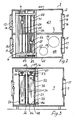
- the apparatus 1 comprises a pair of parallel adjacent ducts, namely a conditioned air duct 4 defining an air stream path for conditioning air, and an ambient air duct 5, both ducts 4, 5 being mounted on a support frame 6 and the ducts 4, 5 having a common side wall 7.
- Each duct 4, 5 has an air inlet 10, 11 and an air outlet 12, 13 respectively.
- Fans 14, 15 are mounted at each outlet 12, 13.
- Air filters 16, 17 are mounted at each air inlet 10, 11.
- a conventional refrigeration unit is located within the ambient air duct 5 and includes a compressor 19, a condenser 20, an evaporator 21 and a liquid refrigerant receiver 22.
- the condenser 20 forms a heater and the evaporator 21 forms a cooler for the air conditioning apparatus 1. Both the condenser 20 and evaporator 21 are independently movable between the two ducts 4, 5 through openings 25, 26, respectively in the side wall 7. Flexible pipes for refrigerant interconnect the condenser 20 and evaporator 21 with each other and with the remainder of the refrigerant unit which is fixed in the ambient air duct 5.
- the condenser 20 and evaporator 21 are both similar heat exchangers. As the construction and mounting arrangement of the evaporator 21 and condenser 20 are the same this is described below for the evaporator 21 only.
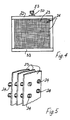
- a number of parallel spaced-apart vertical heat exchange fins 23 are arranged on substantially horizontal tubes 24 of the evaporator 21, the fins 23 extending between a top 32, and a bottom 33 and between front and rear sides 34 of the evaporator 21. These fins 23 are a similar shape to the opening 26 and fit through the opening 26 with a narrow clearance thus forming a closure member for the opening 26.
- Resilient seals 35 mounted at a periphery of the opening 26 extend inwardly to engage front and rear edges of the fins 23. This ensures isolation of air streams delivered through each duct 4, 5 in use.
- the evaporator 21 is slidable along a track extending between outer side walls 40, 41 of the ducts 4, 5 through the opening 26.
- the track is formed by a pair of spaced-apart parallel guide plates 43 depending from the frame 6 at upper ends 44, 45 of the ducts 4, 5 to project downwardly over the front and rear sides 34 of the evaporator 21 at the top 32 of the evaporator 21 and a similar associated pair of guide plates 46 project upwardly from the frame 6 at lower ends 47, 48 of the ducts 4, 5 over the front and rear sides 34 of the evaporator 21 at the bottom 33 of the evaporator 21.
- a mounting bracket 50 is fixed to the top 32 of the evaporator 21.
- a threaded support bar 51 is rotatably mounted in bearings 52 between the sides 40, 41 of the housing 2 above the evaporator 21 and engages a threaded nut 53 fixed on the mounting bracket 50.
- An electric motor (not shown) with an associated reduction gear-box is mounted on the frame 6 and drivably connected to one end of the support bar 51.
- Control means for operation fo the drive means is provided.
- the control means uses conventional equipment which will be readily appreciated by those skilled in the art and therefore is only briefly described below and not shown in the drawings.
- the control means comprises sensors to detect air temperature and air humidity, the sensors being mounted in the conditioned air duct 4 downstream of the condenser 20.
- Signals from the sensors go to a microcomputer which compares the sensed air condition with a pre-set desired air condition.
- the microcomputer controls operation of the refrigeration unit and the electric motors for positioning the condenser 20 at the evaporator 21 within the conditioned air duct 4 to maintain the pre-set desired air condition at the outlet of the conditioned air duct 4.
- the fans 12, 13 are operated to deliver a conditioned air stream through the conditioned air duct 4 and an ambient air stream through the ambient air duct 5 respectively.
- An air delivery conduit (not shown) attached at the outlet 12 of the conditioned air duct 4 directs conditioned air to, for example, a room within which the air is to be conditioned and a return air conduit (not shown) connects the room to the inlet 10 of the conditioned air duct 4.
- the inlet 10 is also preferably connected to a fresh air supply.
- the inlet 11 and outlet 13 of the ambient air duct 5 are open to ambient air.
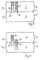
- Cooling of the conditioned air stream is achieved by positioning the evaporator 21 in the conditioned air duct 4 and the condenser 20 in the ambient air duct 5 as shown in Fig. 6. As the conditioned air passes through the evaporator 21, it is cooled to the required temperature.
- Heating the conditioned air stream is effected by locating the condenser 20 within the conditioned air duct 4 and the evaporator 21 within the ambient air duct 5 as shown in Fig. 7. In this case the conditioned air stream passing through the condenser 20 is heated to the required temperature.
- Dehumidification of the conditioned air stream is achieved by having both the evaporator 21 and condenser 20 in the conditioned air duct 4 as shown in Fig. 8. Air passing through the evaporator 21 is cooled, this cooling releasing water from the air which is collected in a water tray (not shown) beneath the evaporator 21. The conditioned air stream is subsequently heated to the required temperature by passing it through the condenser 20. Advantageously portion or all of the heat extracted from the air as it passes through the evaporator 21 is used to heat the air as it passes through the condenser 20.
- Fig. 9 shows both the evaporator 21 and condenser 20 partially within the conditioned air duct 4. It will be appreciated that the transition from one mode, i.e. heating/cooling/dehumidification to another is continuous and this makes the unit suitable for maintaining fine control over air conditioning parameters.
- the condenser and evaporator of the refrigeration system may not be used directly as the heater and cooler respectively of the air conditioning apparatus, but rather secondary heating and cooling circuits are provided. These secondary heating and cooling circuits have a movable heater and cooler respectively mounted on the conditioned air duct. A water or water/glycol mixture for example is circulated between the condenser and heater, and between the evaporator and cooler, for heat transfer between conditioned air in the duct and the refrigeration system.
- the invention enables the refrigeration apparatus to be designed and operated without the compromises required to achieve reverse cycle operation. As the invention uses a simple refrigeration unit it is thus relatively cheap to produce and more reliable in operation.
- movement of the condenser and evaporator may be achieved either manually or automatically in response to signals from an automatic control unit.
- FIG. 10 there is illustrated another air conditioning apparatus 60.
- This apparatus 60 is largely similar to the apparatus descried previously with reference to Figs. 1 to 9 and like parts are assigned the same reference numerals.
- air flow baffles are provided for the evaporator 21 and condenser 20.
- the baffle for the evaporator 21 comprises a porous flexible sheet 62 wound on a rotationally biased roller 63 mounted along an outer edge 64 of the evaporator 25 and extending between a top 32 and bottom 33 of the evaporator 25.
- An outer end 66 of the sheet 62 is fixed along the outer side wall 40 of the conditioned air duct 4 between an upper end 14 and a lower end 47 of the conditioned air duct 4.
- the baffle on the condenser 20 is a similar arrangement to that on the evaporator 25.
- the sheet 62 In use as the evaporator 25 or condenser 26 is retracted into the ambient air duct 5 the sheet 62 unrolls from the roller 63 against spring bias. As the evaporator 25 or condenser 26 is moved into the conditioned air duct 4 the roller 63 automatically winds up the sheet 62.
- the air flow resistance of the sheet 62 is similar to that of the heat exchanger to which it is attached. This advantageously maintains the total air flow through the conditioned air duct substantially constant regardless of the positions of the heat exchangers. it also advantageously ensures that the quantity of air which passes through each heat exchanger is directly proportional to the part of the heat exchanger which is in the conditioned air duct. This arrangement results in a more accurately proportional operation of the air conditioning process.
- baffles would be mounted on inner edges of the heat exchangers and extending between the heat exchangers and the outer side wall 41 of the ambient air duct 5.
- FIG. 11 there is illustrated another air conditioning apparatus 70 largely similar to the air conditioning apparatus described previously with reference to Fig. 10 and like parts are assigned the same reference numerals.
- elastic baffle sheets 71 are mounted between edges 64 of the evaporator 21 and condenser 20 and the outer side wall 40 of the conditioned air duct 4. These baffle sheets 71 simply stretch as the evaporator 21 and condenser 20 are moved into an out of the conditioned air duct 4.
- baffles may be of concertina-like construction to expand and collapse as the heat exchangers are moved between the ducts 4, 5.
- FIG. 12 and Fig. 13 there is illustrated another air conditioning apparatus 80 for mounting on an air duct 81 (shown in broken outline in Fig. 13) to condition air within the air duct 81.
- the apparatus 80 comprises an elongate housing 83 having an air inlet 84 at one end and an air outlet 85 at its other end.
- a fan 86 is mounted at the air outlet 85.
- a refrigeration unit is mounted within the housing 83 and comprises a compressor 88 a condenser 89, an evaporator 90 and a liquid refrigerant receiver 91.
- Both the condenser 89 and the evaporator 90 are slidably mounted on tracks 94, 95 and are extendable outwardly through openings 97, 98 in a side wall 99 of the housing 83.
- Mounting brackets 100 are provided on the side wall 99 for attachment of the apparatus 80 onto a side wall of the duct 81.
- the apparatus 80 is fixed onto a side wall of the duct 81, openings being provided in the duct 81 corresponding to the openings 97, 98 in the housing 83 of the apparatus 80.
- An air stream delivered through the duct 81 can then be conditioned as previously described with reference to the apparatus of Figs. 1 to 9 by moving the condenser 89 and evaporator 90 into and out of the air stream delivered through the duct 81.
- the air conditioning apparatus may be of any suitable materials of construction.
Landscapes
- Engineering & Computer Science (AREA)
- Chemical & Material Sciences (AREA)
- Combustion & Propulsion (AREA)
- Mechanical Engineering (AREA)
- General Engineering & Computer Science (AREA)
- Air Filters, Heat-Exchange Apparatuses, And Housings Of Air-Conditioning Units (AREA)
- Air-Conditioning Room Units, And Self-Contained Units In General (AREA)
- Duct Arrangements (AREA)
- Sorption Type Refrigeration Machines (AREA)
- Air Humidification (AREA)
Applications Claiming Priority (2)
| Application Number | Priority Date | Filing Date | Title |
|---|---|---|---|
| IE327389A IE68039B1 (en) | 1989-10-11 | 1989-10-11 | An air conditioning apparatus |
| IE327389 | 1989-10-11 |
Publications (3)
| Publication Number | Publication Date |
|---|---|
| EP0422942A2 true EP0422942A2 (de) | 1991-04-17 |
| EP0422942A3 EP0422942A3 (en) | 1992-03-18 |
| EP0422942B1 EP0422942B1 (de) | 1995-05-10 |
Family
ID=11038255
Family Applications (1)
| Application Number | Title | Priority Date | Filing Date |
|---|---|---|---|
| EP90311174A Expired - Lifetime EP0422942B1 (de) | 1989-10-11 | 1990-10-11 | Klimagerät |
Country Status (6)
| Country | Link |
|---|---|
| EP (1) | EP0422942B1 (de) |
| AT (1) | ATE122448T1 (de) |
| DE (1) | DE69019285T2 (de) |
| DK (1) | DK0422942T3 (de) |
| ES (1) | ES2074542T3 (de) |
| IE (1) | IE68039B1 (de) |
Cited By (2)
| Publication number | Priority date | Publication date | Assignee | Title |
|---|---|---|---|---|
| EP0512945A3 (en) * | 1991-05-08 | 1993-07-14 | Wieler & Durian Anlagentechnik Gmbh | Device for conditioning rooms |
| CN106931535A (zh) * | 2017-05-03 | 2017-07-07 | 珠海格力电器股份有限公司 | 空调器 |
Families Citing this family (3)
| Publication number | Priority date | Publication date | Assignee | Title |
|---|---|---|---|---|
| DE19911645A1 (de) * | 1999-03-16 | 2000-09-21 | Volkswagen Ag | Heizvorrichtung zur Erwärmung eines Luftstroms |
| DE102007035240A1 (de) * | 2007-07-25 | 2009-01-29 | Behr Gmbh & Co. Kg | Heizungs- und/oder Klimatisierungseinrichtung für ein Kraftfahrzeug |
| CN110624316B (zh) * | 2018-06-25 | 2021-07-30 | 颉能科技股份有限公司 | 集水器 |
Family Cites Families (3)
| Publication number | Priority date | Publication date | Assignee | Title |
|---|---|---|---|---|
| US2147283A (en) * | 1938-01-19 | 1939-02-14 | Hart & Cooley Mfg Company | Heating device |
| DE2252977C3 (de) * | 1972-10-28 | 1978-03-02 | Eskawe Kaelte- Und Waermetechnik Gmbh, 2000 Hamburg | Induktions-Klimagerät für Hochdruckklimaanlagen |
| US4621683A (en) * | 1983-03-14 | 1986-11-11 | Ford Motor Company | Heat exchanger with valved pipe connection |
-
1989
- 1989-10-11 IE IE327389A patent/IE68039B1/en not_active IP Right Cessation
-
1990
- 1990-10-11 EP EP90311174A patent/EP0422942B1/de not_active Expired - Lifetime
- 1990-10-11 ES ES90311174T patent/ES2074542T3/es not_active Expired - Lifetime
- 1990-10-11 AT AT90311174T patent/ATE122448T1/de not_active IP Right Cessation
- 1990-10-11 DE DE69019285T patent/DE69019285T2/de not_active Expired - Fee Related
- 1990-10-11 DK DK90311174.8T patent/DK0422942T3/da active
Cited By (2)
| Publication number | Priority date | Publication date | Assignee | Title |
|---|---|---|---|---|
| EP0512945A3 (en) * | 1991-05-08 | 1993-07-14 | Wieler & Durian Anlagentechnik Gmbh | Device for conditioning rooms |
| CN106931535A (zh) * | 2017-05-03 | 2017-07-07 | 珠海格力电器股份有限公司 | 空调器 |
Also Published As
| Publication number | Publication date |
|---|---|
| EP0422942B1 (de) | 1995-05-10 |
| ES2074542T3 (es) | 1995-09-16 |
| IE893273A1 (en) | 1991-04-24 |
| IE68039B1 (en) | 1996-05-15 |
| ATE122448T1 (de) | 1995-05-15 |
| DE69019285T2 (de) | 1996-01-18 |
| EP0422942A3 (en) | 1992-03-18 |
| DE69019285D1 (de) | 1995-06-14 |
| DK0422942T3 (da) | 1995-10-09 |
Similar Documents
| Publication | Publication Date | Title |
|---|---|---|
| US5237831A (en) | Air conditioning apparatus | |
| US5400607A (en) | System and method for high-efficiency air cooling and dehumidification | |
| US5598715A (en) | Central air handling and conditioning apparatus including by-pass dehumidifier | |
| US7174741B2 (en) | Air conditioner | |
| US7162889B2 (en) | Air conditioner | |
| KR0129641Y1 (ko) | 공기조화기의 실내기 | |
| US20080000630A1 (en) | Ventilator system and method | |
| US4485642A (en) | Adjustable heat exchanger air bypass for humidity control | |
| EP1632730A2 (de) | Ventilator und Klimaanlage mit diesem Ventilator | |
| US4742957A (en) | Heat recovery ventilator | |
| EP0422942B1 (de) | Klimagerät | |
| KR100352440B1 (ko) | 휴대용 냉난방장치 | |
| US5069041A (en) | Method and apparatus for electromechanical air conditioning of industrial electronics | |
| HU224449B1 (hu) | Hőcserélő egység, főleg épület szellőzéséhez | |
| EP0442028B1 (de) | Zweifachinstallation für ein Klimagerät | |
| GB2036299A (en) | Space heating units | |
| US5476419A (en) | Thermally actuated heating/cooling air changeover deflector structure for a ceiling diffuser | |
| JP3583912B2 (ja) | 空気調和機 | |
| US20080083230A1 (en) | Apparatus and method for enhanced dehumidification | |
| JP3716459B2 (ja) | 車両用空気調和機 | |
| FI120705B (fi) | Jäähdytyslaitteisto sisäilman jäähdyttämiseksi | |
| CN223954276U (zh) | 空调室内机 | |
| US20110139403A1 (en) | Heat Exchanger | |
| KR930004184Y1 (ko) | 공기 조화기 | |
| KR102581875B1 (ko) | 차량용 공조장치 |
Legal Events
| Date | Code | Title | Description |
|---|---|---|---|
| PUAI | Public reference made under article 153(3) epc to a published international application that has entered the european phase |
Free format text: ORIGINAL CODE: 0009012 |
|
| AK | Designated contracting states |
Kind code of ref document: A2 Designated state(s): AT BE CH DE DK ES FR GB GR IT LI LU NL SE |
|
| PUAL | Search report despatched |
Free format text: ORIGINAL CODE: 0009013 |
|
| AK | Designated contracting states |
Kind code of ref document: A3 Designated state(s): AT BE CH DE DK ES FR GB GR IT LI LU NL SE |
|
| 17P | Request for examination filed |
Effective date: 19920918 |
|
| 17Q | First examination report despatched |
Effective date: 19930827 |
|
| GRAA | (expected) grant |
Free format text: ORIGINAL CODE: 0009210 |
|
| RAP1 | Party data changed (applicant data changed or rights of an application transferred) |
Owner name: FORFAS |
|
| AK | Designated contracting states |
Kind code of ref document: B1 Designated state(s): AT BE CH DE DK ES FR GB GR IT LI LU NL SE |
|
| PG25 | Lapsed in a contracting state [announced via postgrant information from national office to epo] |
Ref country code: LI Effective date: 19950510 Ref country code: GR Free format text: LAPSE BECAUSE OF FAILURE TO SUBMIT A TRANSLATION OF THE DESCRIPTION OR TO PAY THE FEE WITHIN THE PRESCRIBED TIME-LIMIT Effective date: 19950510 Ref country code: CH Effective date: 19950510 Ref country code: BE Effective date: 19950510 Ref country code: AT Effective date: 19950510 |
|
| REF | Corresponds to: |
Ref document number: 122448 Country of ref document: AT Date of ref document: 19950515 Kind code of ref document: T |
|
| REF | Corresponds to: |
Ref document number: 69019285 Country of ref document: DE Date of ref document: 19950614 |
|
| ITF | It: translation for a ep patent filed | ||
| PG25 | Lapsed in a contracting state [announced via postgrant information from national office to epo] |
Ref country code: SE Effective date: 19950810 |
|
| REG | Reference to a national code |
Ref country code: CH Ref legal event code: PL |
|
| ET | Fr: translation filed | ||
| REG | Reference to a national code |
Ref country code: ES Ref legal event code: FG2A Ref document number: 2074542 Country of ref document: ES Kind code of ref document: T3 |
|
| REG | Reference to a national code |
Ref country code: DK Ref legal event code: T3 |
|
| PG25 | Lapsed in a contracting state [announced via postgrant information from national office to epo] |
Ref country code: LU Free format text: LAPSE BECAUSE OF NON-PAYMENT OF DUE FEES Effective date: 19951031 |
|
| PLBE | No opposition filed within time limit |
Free format text: ORIGINAL CODE: 0009261 |
|
| STAA | Information on the status of an ep patent application or granted ep patent |
Free format text: STATUS: NO OPPOSITION FILED WITHIN TIME LIMIT |
|
| 26N | No opposition filed | ||
| PGFP | Annual fee paid to national office [announced via postgrant information from national office to epo] |
Ref country code: FR Payment date: 19960920 Year of fee payment: 7 |
|
| PGFP | Annual fee paid to national office [announced via postgrant information from national office to epo] |
Ref country code: DK Payment date: 19961009 Year of fee payment: 7 |
|
| PGFP | Annual fee paid to national office [announced via postgrant information from national office to epo] |
Ref country code: NL Payment date: 19961031 Year of fee payment: 7 |
|
| PGFP | Annual fee paid to national office [announced via postgrant information from national office to epo] |
Ref country code: DE Payment date: 19961220 Year of fee payment: 7 |
|
| REG | Reference to a national code |
Ref country code: DK Ref legal event code: EBP |
|
| PG25 | Lapsed in a contracting state [announced via postgrant information from national office to epo] |
Ref country code: FR Free format text: THE PATENT HAS BEEN ANNULLED BY A DECISION OF A NATIONAL AUTHORITY Effective date: 19971031 Ref country code: DK Free format text: LAPSE BECAUSE OF NON-PAYMENT OF DUE FEES Effective date: 19971031 |
|
| PGFP | Annual fee paid to national office [announced via postgrant information from national office to epo] |
Ref country code: GB Payment date: 19980407 Year of fee payment: 8 |
|
| PGFP | Annual fee paid to national office [announced via postgrant information from national office to epo] |
Ref country code: ES Payment date: 19980430 Year of fee payment: 8 |
|
| PG25 | Lapsed in a contracting state [announced via postgrant information from national office to epo] |
Ref country code: NL Free format text: LAPSE BECAUSE OF NON-PAYMENT OF DUE FEES Effective date: 19980501 |
|
| NLV4 | Nl: lapsed or anulled due to non-payment of the annual fee |
Effective date: 19980501 |
|
| PG25 | Lapsed in a contracting state [announced via postgrant information from national office to epo] |
Ref country code: DE Free format text: LAPSE BECAUSE OF NON-PAYMENT OF DUE FEES Effective date: 19980701 |
|
| REG | Reference to a national code |
Ref country code: FR Ref legal event code: ST |
|
| PG25 | Lapsed in a contracting state [announced via postgrant information from national office to epo] |
Ref country code: GB Free format text: LAPSE BECAUSE OF NON-PAYMENT OF DUE FEES Effective date: 19981011 |
|
| PG25 | Lapsed in a contracting state [announced via postgrant information from national office to epo] |
Ref country code: ES Free format text: LAPSE BECAUSE OF EXPIRATION OF PROTECTION Effective date: 19981013 |
|
| GBPC | Gb: european patent ceased through non-payment of renewal fee |
Effective date: 19981011 |
|
| REG | Reference to a national code |
Ref country code: ES Ref legal event code: FD2A Effective date: 20010201 |
|
| PG25 | Lapsed in a contracting state [announced via postgrant information from national office to epo] |
Ref country code: IT Free format text: LAPSE BECAUSE OF NON-PAYMENT OF DUE FEES;WARNING: LAPSES OF ITALIAN PATENTS WITH EFFECTIVE DATE BEFORE 2007 MAY HAVE OCCURRED AT ANY TIME BEFORE 2007. THE CORRECT EFFECTIVE DATE MAY BE DIFFERENT FROM THE ONE RECORDED. Effective date: 20051011 |