EP0423013A1 - System zur Steuerung eines beweglichen Armes, verbunden mit einem Fahrzeug zur Überwindung von Graten - Google Patents
System zur Steuerung eines beweglichen Armes, verbunden mit einem Fahrzeug zur Überwindung von Graten Download PDFInfo
- Publication number
- EP0423013A1 EP0423013A1 EP90402792A EP90402792A EP0423013A1 EP 0423013 A1 EP0423013 A1 EP 0423013A1 EP 90402792 A EP90402792 A EP 90402792A EP 90402792 A EP90402792 A EP 90402792A EP 0423013 A1 EP0423013 A1 EP 0423013A1
- Authority
- EP
- European Patent Office
- Prior art keywords
- arm
- vehicle
- control system
- bypass
- liquid
- Prior art date
- Legal status (The legal status is an assumption and is not a legal conclusion. Google has not performed a legal analysis and makes no representation as to the accuracy of the status listed.)
- Granted
Links
Images


Classifications
-
- B—PERFORMING OPERATIONS; TRANSPORTING
- B62—LAND VEHICLES FOR TRAVELLING OTHERWISE THAN ON RAILS
- B62D—MOTOR VEHICLES; TRAILERS
- B62D55/00—Endless track vehicles
- B62D55/06—Endless track vehicles with tracks without ground wheels
- B62D55/075—Tracked vehicles for ascending or descending stairs, steep slopes or vertical surfaces
Definitions
- the invention relates to a control system of a mobile arm dependent on a vehicle and used for crossing ridges and has in particular been designed to be used on the vehicle described in the French patent with registration number 87 02098 .
- This patent describes a tracked vehicle that can be moved on floors with variable slopes; the crests are defined as connections of different slopes delimiting projections.
- the vehicle travels on landings and stairs, and the ridges are then the connections of a staircase and an upper landing.
- the arm When the vehicle begins to overhang the landing after having climbed the stairs and is about to tip over, you extend the arm at the front of the vehicle until it touches the ground at one end and it is brought back to small in the retracted position during the subsequent advance of the vehicle so that the latter only gradually falls back into the horizontal position.
- the arm is also deployed when the vehicle is about to arrive on a descending staircase: the vehicle is brought to an inclination equal to or in practice a little greater than that of the staircase. This avoids any sudden tilting and, when the center of gravity of the vehicle overhangs the staircase, the arm can be folded.
- the vehicle is also tilted excessively when it approaches a descending staircase, and no means of adjusting the deployment of the arm is indicated in this prior patent.
- the invention described below aims to solve these problems and above all to make the crossing of ridges and the return to horizontal smoother by preventing excessive deployments of the arm. Certain variants of the invention also make it possible not to retract the arm too quickly or to limit the inclination of the vehicle during the descent. Finally, the invention can be used on routes comprising, for example, slopes or stairs of different inclinations.
- the invention is thus grafted onto a control system for a movable arm moved between a retracted position and a position deployed by movements in opposite directions, the arm being dependent on a vehicle moving on a ground having variable slopes separated by ridges, the retracted position corresponding to a state where the arm is raised from the ground and the deployed position to a state where a lower end of the arm is directed towards the ground, comprising a jack composed of a cylinder filled with liquid, a piston sliding in the cylinder and separating it into two sealed chambers, a rod connected to the piston and to the arm, a source of pressurized liquid and a liquid reservoir, two pipes each leading to a respective chamber, a distributor with three states capable of blocking the two pipes and of connecting each of them to the source of pressurized liquid, the other pipe then being connected to the liquid tank.
- these means consist of a bypass connecting a first chamber, the volume of which increases when the arm is moved towards the deployed position, to the liquid reservoir via a flow limiter, a second bypass connecting the second chamber to the liquid tank, and a distribution system to open and close the two branches.
- the second bypass is advantageously provided with a flow limiter.
- the system may also include an inclination detector fixed to the vehicle and logic means comparing the inclination of the vehicle measured by the detector and a reference inclination and ordering partial movements of the arm towards its retracted position when the inclination of the vehicle exceeds the reference tilt.
- a simpler embodiment of the invention uses a ground contact sensor which comprises a part connected to the arm in a mobile manner and ending below the free end of the arm, as well as a switch switched when the mobile part is moved by contact with the ground.
- the vehicle referenced by 1 in FIG. 1, is composed in particular of two tracks 2 and of an arm 3 pivoting around a joint 4 fixed on the vehicle 1 between a deployed position indicated by the line 5 and a retracted position indicated by line 6.
- the pivoting of the arm 3 is controlled by a jack 7 conventionally constituted by a cylinder 8 in which slides a piston 9, to which is connected a rod 10 which crosses the cylinder 8 and ends by a hinge 28 at mid -length of the arm 3.
- the interior of the cylinder 8 is divided in leaktight manner into a first chamber 11 or bottom chamber, the volume of which increases when the arm 3 is moved to its deployed position, and a second chamber 12 by the piston 9.
- a first pipe 13 and a second pipe 14 respectively connect the first and second chambers 11 and 12 to a progressive distributor 15 electromagnetically controlled, provided with return springs and capable of taking three fundamental states.
- the progressive distributor 15 is also connected to a source of pressurized oil P and to an oil tank B. When it is not controlled, it is closed and closes the first and second lines 13 and 14; when ordered, it can take two open states where it connects one or the other of lines 13 and 14 to the source of pressurized oil P and the other line to tank B, thus creating in the rooms 11 and 12 a pressure difference which moves the piston 9 and the arm 3 at a speed which depends on the intensity of the current which passes through the electromagnetic means for controlling the progressive valve 15 and therefore opens it more or less.
- Two branches 16 and 17 respectively connect the two chambers 11 and 12 or, as shown here, their associated pipes 13 and 14 to the cover B.
- a distribution system enables the two branches 16 and 17 to be closed or opened simultaneously.
- two identical distributors 18 and 19 are used with electromagnetic control and spring return. In the non-excited state, the branches 16 and 17 are closed.
- the first branch 16 is provided with a pressure limiter 20 which authorizes the flow of oil from the first chamber 11 to the tank B only above a determined pressure which can moreover be adjusted by the user by modifying the setting of the return spring 26 of the pressure limiter 20.
- the second bypass 17 is provided with a flow limiter 21. Bypasses 22 and 23 bypass the pressure limiter 20 and the distributor 18 respectively. on the one hand, the flow limiter 21 on the other hand; each of the by-passes 22 and 23 is provided with a non-return valve 24 and 25 which authorizes the flow there only from the tank B towards the associated chamber 11 or 12.
- the arm 3 which had previously been brought back to the retracted position 6, is deployed .
- the two distributors 18 and 19 are excited for this while maintaining the progressive distributor 15 in the non-excited state.
- the arm 3 falls under the effect of gravity, the oil flowing from the cover B towards the first chamber 11 by the first bypass 22 and from the second chamber 12 towards the cover B by the second bypass 17.
- This second flow is however braked by the flow limiter 21, so that the descent of the arm 3 continues at moderate speed until a idler wheel 27 at the free end of the arm 3 reaches the bearing N and the center of gravity of the vehicle 1 arrives at the base of the crest CR.
- the vehicle 1 then begins to fall and the arm 3 returns to the retracted position 6, but this movement is also gradual because the flow from the first chamber 11 towards the cover B which is then established is braked by the pressure limiter 20. It is advantageous to adjust the pressure relief valve 20 so that it only authorizes flows at a pressure slightly lower than the pressure exerted by the piston 9 in the first chamber 11 by the weight of the vehicle 1 supported by arm 3. We are then in quasi-static regime.
- the movement of the arm 3 stops when the vehicle 1 has become horizontal again and only carries on its tracks 2.
- the excitation of the distributors 18 and 19 ceases and the progressive distributor 15 is excited to return the arm 3 to the retracted position 6 .
- bypass 22 and 23 are sup award-winning as well as the flow limiter 21.
- the distributors 18 and 19 are also replaced by a single two-way distributor 29 with electromagnetic control and return means which, here again, opens the branches 16 and 17 in the excited state. and closes them the rest of the time.
- a sub-branch 30 connects the source of pressurized oil P to a point on the first branch 16 located between the two-way distributor 29 and the pressure limiter 20.
- the sub-branch 30 is provided with a pressure reducer 31 and of a one-way valve 32 which authorizes flow only to the first chamber 11.
- the use of a two-way distributor 29 leads to a simplification of the device.
- the sub-bypass 30 also makes it possible to introduce oil more quickly into the first chamber 11 and therefore to accelerate the deployment of the arm 3 without however making it too abrupt.
- the valve 32 prevents oil returns to the pressure reducer 31 when the vehicle 1 falls.
- the arm 3 On a level N, the arm 3 gives the vehicle an inclination which is 17 ° in the embodiment constructed when it is in the deployed position 5 and the stairs E which it is necessary to descend have an average slope of 27 °.
- the vehicle when the vehicle is preparing to descend a staircase E, it does, however, bear on it only by its part remote from the arm 3 (still pressing on the bearing N) and therefore takes a greater inclination at the slope of the staircase E, which endangers its stability. This is why the vehicle 1 carries a system which includes an inclination detector or inclinometer 36 and a reference inclination generator 37.
- the inclinometer 36 provides a proportional voltage at the inclination of the vehicle 1 and the reference inclination generator 37, another voltage proportional to the reference value by a converter 38.
- a comparator 39 makes it possible to subtract these two voltages and to act on the progressive distributor via an amplifier 40.
- the value of the reference inclination is established at a value slightly greater than the average slope of the staircase (28 ° in this case) and, as soon as the inclinometer 36 notes an equal or greater value, the progressive distributor 15 is excited so as to make oil penetrate into the second chamber 12 to slightly retract the arm 3.
- the arm 3 is thus gradually retracted until the inclinometer 36 detects an inclination at most equal to 28 °.
- the retraction of the arm 3 is resumed as soon as the inclinometer 36 again marks an indication exceeding this value.
- the inclination of the vehicle 1 remains stationary at 27 °, its tracks 2 rest on the staircase E over their entire length and the arm 3 can be fully retracted.
- the reference tilt generator 37, as well as the distributors 18, 19 and 29, can be controlled by the driver or by ground slope variation sensors such as those mentioned in the aforementioned prior patent.
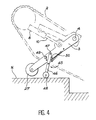
- FIG. 4 A simplified embodiment of the invention is shown in FIG. 4. It makes it possible to dispense with the hydraulic system described above and in particular of the solenoid valves 18 and 19 and of the limiters 20 and 21.
- a ground contact sensor 45 is used here.
- an articulated rod 46 by one end 47 to the arm 3, near the idler wheel 27.
- the other end of the connecting rod 46 carries a caster 48 which protrudes from the idler wheel 27 from below when the arm 3 is lifted from the ground. But when the arm 3 is deployed and on the point of reaching the bearing N, the contact of the caster 48 turns the connecting rod 46 which then comes to touch a switch 49.
- the movements of the arm 3 may depend solely on the progressive distributor 15 which is then slaved to the switch 49 or controlled by the driver, if there is one, using the indications of the switch 49 displayed on the dashboard.
- the progressive distributor 15 is controlled so that the flow rate which passes through it is reduced or eliminated. This avoids excessive deployments of the arm 3.
- a protruding cleat 50 of the arm 3 serves as a rotational stop for the connecting rod 46 and prevents it from hanging vertically.
- This embodiment of the invention can be combined with the previous one on the same vehicle.
Landscapes
- Engineering & Computer Science (AREA)
- Chemical & Material Sciences (AREA)
- Combustion & Propulsion (AREA)
- Transportation (AREA)
- Mechanical Engineering (AREA)
- Vehicle Body Suspensions (AREA)
- Vehicle Cleaning, Maintenance, Repair, Refitting, And Outriggers (AREA)
- Steering-Linkage Mechanisms And Four-Wheel Steering (AREA)
- Finish Polishing, Edge Sharpening, And Grinding By Specific Grinding Devices (AREA)
Applications Claiming Priority (2)
| Application Number | Priority Date | Filing Date | Title |
|---|---|---|---|
| FR8913156A FR2652925B1 (fr) | 1989-10-09 | 1989-10-09 | Systeme de commande d'un bras mobile dependant d'un vehicule et utilise pour le franchissement de cretes. |
| FR8913156 | 1989-10-09 |
Publications (2)
| Publication Number | Publication Date |
|---|---|
| EP0423013A1 true EP0423013A1 (de) | 1991-04-17 |
| EP0423013B1 EP0423013B1 (de) | 1995-02-01 |
Family
ID=9386206
Family Applications (1)
| Application Number | Title | Priority Date | Filing Date |
|---|---|---|---|
| EP90402792A Expired - Lifetime EP0423013B1 (de) | 1989-10-09 | 1990-10-08 | System zur Steuerung eines beweglichen Armes, verbunden mit einem Fahrzeug zur Überwindung von Graten |
Country Status (4)
| Country | Link |
|---|---|
| EP (1) | EP0423013B1 (de) |
| AT (1) | ATE117957T1 (de) |
| DE (1) | DE69016566D1 (de) |
| FR (1) | FR2652925B1 (de) |
Cited By (7)
| Publication number | Priority date | Publication date | Assignee | Title |
|---|---|---|---|---|
| KR100811860B1 (ko) | 2006-08-18 | 2008-03-10 | 한양대학교 산학협력단 | 장애물 지대 극복 로봇 |
| ITTO20100071A1 (it) * | 2010-02-02 | 2011-08-03 | Oto Melara Spa | Dispositivo di smorzamento di sobbalzi di un veicolo cingolato e veicolo cingolato associato. |
| EP2436012A4 (de) * | 2009-05-27 | 2014-03-19 | Brooks R Ass Inc | Inspektionswerkzeuge für oberes bündel eines dampfgenerators |
| WO2014138439A1 (en) * | 2013-03-06 | 2014-09-12 | Massachusetts Institute Of Technology | Discrete motion system |
| CN110328651A (zh) * | 2019-07-29 | 2019-10-15 | 东北大学 | 面向老人的可越障陪护机器人 |
| CN111572672A (zh) * | 2020-06-01 | 2020-08-25 | 武义普巴机械设备有限公司 | 一种可爬楼梯的自动装卸运输车 |
| KR102318510B1 (ko) * | 2021-03-10 | 2021-10-27 | 박찬웅 | 장애물 극복 유닛 및 이를 구비한 무한 궤도 장치 |
Families Citing this family (1)
| Publication number | Priority date | Publication date | Assignee | Title |
|---|---|---|---|---|
| EP4100299A4 (de) * | 2020-02-04 | 2024-03-13 | Movex Innovation Inc. | Neigungssteuersystem für kettenfahrzeug |
Citations (2)
| Publication number | Priority date | Publication date | Assignee | Title |
|---|---|---|---|---|
| WO1987002634A1 (en) * | 1985-10-29 | 1987-05-07 | The Secretary Of State For Defence In Her Britanni | Obstacle surmounting aid for tracked vehicle |
| FR2610885A1 (fr) * | 1987-02-18 | 1988-08-19 | Protee | Vehicule motorise a chenilles avec bras articules pour franchissement d'obstacles |
Family Cites Families (1)
| Publication number | Priority date | Publication date | Assignee | Title |
|---|---|---|---|---|
| JPS5920777A (ja) * | 1982-07-24 | 1984-02-02 | Furukawa Mining Co Ltd | 運搬車 |
-
1989
- 1989-10-09 FR FR8913156A patent/FR2652925B1/fr not_active Expired - Fee Related
-
1990
- 1990-10-08 AT AT90402792T patent/ATE117957T1/de not_active IP Right Cessation
- 1990-10-08 DE DE69016566T patent/DE69016566D1/de not_active Expired - Lifetime
- 1990-10-08 EP EP90402792A patent/EP0423013B1/de not_active Expired - Lifetime
Patent Citations (2)
| Publication number | Priority date | Publication date | Assignee | Title |
|---|---|---|---|---|
| WO1987002634A1 (en) * | 1985-10-29 | 1987-05-07 | The Secretary Of State For Defence In Her Britanni | Obstacle surmounting aid for tracked vehicle |
| FR2610885A1 (fr) * | 1987-02-18 | 1988-08-19 | Protee | Vehicule motorise a chenilles avec bras articules pour franchissement d'obstacles |
Non-Patent Citations (1)
| Title |
|---|
| PATENT ABSTRACTS OF JAPAN, vol. 8, no. 112 (M-298)[1549], 25 mai 1984; & JP-A-59 20 777 (FURUKAWA KOGYO K.K.) 02-02-1984 * |
Cited By (10)
| Publication number | Priority date | Publication date | Assignee | Title |
|---|---|---|---|---|
| KR100811860B1 (ko) | 2006-08-18 | 2008-03-10 | 한양대학교 산학협력단 | 장애물 지대 극복 로봇 |
| EP2436012A4 (de) * | 2009-05-27 | 2014-03-19 | Brooks R Ass Inc | Inspektionswerkzeuge für oberes bündel eines dampfgenerators |
| US9251921B2 (en) | 2009-05-27 | 2016-02-02 | R. Brooks Associates, Inc. | Steam generator upper bundle inspection tools |
| EP3147910A1 (de) * | 2009-05-27 | 2017-03-29 | Rolls-Royce Nuclear Field Services Inc. | Verfahrbares inspektionssystem für die sekundärseite eines dampferzeugers |
| ITTO20100071A1 (it) * | 2010-02-02 | 2011-08-03 | Oto Melara Spa | Dispositivo di smorzamento di sobbalzi di un veicolo cingolato e veicolo cingolato associato. |
| EP2353975A1 (de) * | 2010-02-02 | 2011-08-10 | Oto Melara S.p.A. | Vorrichtung zur Dämpfung von Erschütterungen eines Kettenfahrzeugs und zugehöriges Kettenfahrzeug |
| WO2014138439A1 (en) * | 2013-03-06 | 2014-09-12 | Massachusetts Institute Of Technology | Discrete motion system |
| CN110328651A (zh) * | 2019-07-29 | 2019-10-15 | 东北大学 | 面向老人的可越障陪护机器人 |
| CN111572672A (zh) * | 2020-06-01 | 2020-08-25 | 武义普巴机械设备有限公司 | 一种可爬楼梯的自动装卸运输车 |
| KR102318510B1 (ko) * | 2021-03-10 | 2021-10-27 | 박찬웅 | 장애물 극복 유닛 및 이를 구비한 무한 궤도 장치 |
Also Published As
| Publication number | Publication date |
|---|---|
| ATE117957T1 (de) | 1995-02-15 |
| FR2652925B1 (fr) | 1994-02-18 |
| FR2652925A1 (fr) | 1991-04-12 |
| EP0423013B1 (de) | 1995-02-01 |
| DE69016566D1 (de) | 1995-03-16 |
Similar Documents
| Publication | Publication Date | Title |
|---|---|---|
| EP0739286B1 (de) | Selbstlenkungsarm eines strassenfahrzeugs entlang einer leitschiene | |
| FR2691187A1 (fr) | Procédé pour commander automatiquement le moteur d'orientation d'une excavatrice. | |
| FR2639016A1 (fr) | Dispositif de stabilisation pour vehicule inclinable | |
| EP0423013B1 (de) | System zur Steuerung eines beweglichen Armes, verbunden mit einem Fahrzeug zur Überwindung von Graten | |
| EP0389378B1 (de) | Hebebühne für Fahrzeuge und Handhabungsverfahren | |
| EP1399357B1 (de) | Gelenkfahrzeug | |
| FR2528085A1 (fr) | Dispositif gravillonneur porte | |
| EP0041901B1 (de) | Vorrichtung zum Greifen eines Containers oder dgl. mit Niveaudetektoren | |
| FR2473029A1 (fr) | Pont elevateur, transporteur ou basculant, actionne hydrauliquement | |
| FR2470079A1 (fr) | Appareil de manutention pour le support et le levage des charges | |
| FR2496613A2 (fr) | Appareil de reprise de matieres en vrac | |
| FR2503055A1 (fr) | Suspension pour vehicule | |
| WO1997000803A1 (fr) | Dispositif de stabilisation a l'arret escamotable, pour engin motorise a deux roues, et procede associe | |
| FR2877656A1 (fr) | Systeme de plate-forme elevatrice | |
| EP1348666A1 (de) | Olzuführvorrichtung in der hydraulischen Ausgleichleitung von einem verstellbaren Kranausleger | |
| FR2655131A1 (fr) | Dispositif de reglage et de conservation de l'assiette d'un support mobile verticalement. | |
| FR2683295A1 (fr) | Appareil de pose automatique d'un joint dans le nez de robinet d'une bouteille de gaz. | |
| BE1001764A3 (fr) | Systeme de commande de la hauteur de chassis d'un vehicule a suspension pneumatique. | |
| FR2527155A1 (fr) | Appareil pour la manutention de charges | |
| EP0029393B1 (de) | Ladevorrichtung von der Art einer Hebebühne, die ins Innere eines Fahrzeuges einklappbar ist | |
| EP3705364A1 (de) | Stabilisator eines fahrzeugs | |
| FR2596378A1 (fr) | Dispositif chargeur a compensation rapide et blocage pour tracteurs agricoles et analogues | |
| FR2551490A1 (fr) | Echelle mobile pour vehicule ou engin possedant une plate-forme elevee et/ou difficile d'acces avec poste de conduite et systeme de commande de ladite echelle | |
| FR2869284A1 (fr) | Chassis de chariot a guidage bi-fonctionnel | |
| FR2877359A1 (fr) | Dispositif de manoeuvre de hausses de barrage hydraulique, systeme de bouchure mobile pour barrage hydraulique et procede de manoeuvre de hausses de barrage hydraulique |
Legal Events
| Date | Code | Title | Description |
|---|---|---|---|
| PUAI | Public reference made under article 153(3) epc to a published international application that has entered the european phase |
Free format text: ORIGINAL CODE: 0009012 |
|
| AK | Designated contracting states |
Kind code of ref document: A1 Designated state(s): AT BE CH DE ES GB GR IT LI LU NL SE |
|
| 17P | Request for examination filed |
Effective date: 19910920 |
|
| 17Q | First examination report despatched |
Effective date: 19930407 |
|
| GRAA | (expected) grant |
Free format text: ORIGINAL CODE: 0009210 |
|
| AK | Designated contracting states |
Kind code of ref document: B1 Designated state(s): AT BE CH DE ES GB GR IT LI LU NL SE |
|
| PG25 | Lapsed in a contracting state [announced via postgrant information from national office to epo] |
Ref country code: IT Free format text: LAPSE BECAUSE OF FAILURE TO SUBMIT A TRANSLATION OF THE DESCRIPTION OR TO PAY THE FEE WITHIN THE PRESCRIBED TIME-LIMIT;WARNING: LAPSES OF ITALIAN PATENTS WITH EFFECTIVE DATE BEFORE 2007 MAY HAVE OCCURRED AT ANY TIME BEFORE 2007. THE CORRECT EFFECTIVE DATE MAY BE DIFFERENT FROM THE ONE RECORDED. Effective date: 19950201 Ref country code: GB Effective date: 19950201 Ref country code: GR Free format text: LAPSE BECAUSE OF FAILURE TO SUBMIT A TRANSLATION OF THE DESCRIPTION OR TO PAY THE FEE WITHIN THE PRESCRIBED TIME-LIMIT Effective date: 19950201 Ref country code: ES Free format text: THE PATENT HAS BEEN ANNULLED BY A DECISION OF A NATIONAL AUTHORITY Effective date: 19950201 Ref country code: NL Effective date: 19950201 Ref country code: AT Effective date: 19950201 |
|
| REF | Corresponds to: |
Ref document number: 117957 Country of ref document: AT Date of ref document: 19950215 Kind code of ref document: T |
|
| REF | Corresponds to: |
Ref document number: 69016566 Country of ref document: DE Date of ref document: 19950316 |
|
| PG25 | Lapsed in a contracting state [announced via postgrant information from national office to epo] |
Ref country code: SE Effective date: 19950501 |
|
| PG25 | Lapsed in a contracting state [announced via postgrant information from national office to epo] |
Ref country code: DE Effective date: 19950503 |
|
| NLV1 | Nl: lapsed or annulled due to failure to fulfill the requirements of art. 29p and 29m of the patents act | ||
| GBV | Gb: ep patent (uk) treated as always having been void in accordance with gb section 77(7)/1977 [no translation filed] |
Effective date: 19950201 |
|
| PG25 | Lapsed in a contracting state [announced via postgrant information from national office to epo] |
Ref country code: LI Effective date: 19951031 Ref country code: BE Effective date: 19951031 Ref country code: CH Effective date: 19951031 Ref country code: LU Free format text: LAPSE BECAUSE OF NON-PAYMENT OF DUE FEES Effective date: 19951031 |
|
| PLBE | No opposition filed within time limit |
Free format text: ORIGINAL CODE: 0009261 |
|
| STAA | Information on the status of an ep patent application or granted ep patent |
Free format text: STATUS: NO OPPOSITION FILED WITHIN TIME LIMIT |
|
| 26N | No opposition filed | ||
| BERE | Be: lapsed |
Owner name: PROTEE GROUPEMENT D'INTERET ECONOMIQUE Effective date: 19951031 |
|
| REG | Reference to a national code |
Ref country code: CH Ref legal event code: PL |