EP0423060B1 - Raccord pour tube combiné avec pompe à jet - Google Patents
Raccord pour tube combiné avec pompe à jet Download PDFInfo
- Publication number
- EP0423060B1 EP0423060B1 EP19900630174 EP90630174A EP0423060B1 EP 0423060 B1 EP0423060 B1 EP 0423060B1 EP 19900630174 EP19900630174 EP 19900630174 EP 90630174 A EP90630174 A EP 90630174A EP 0423060 B1 EP0423060 B1 EP 0423060B1
- Authority
- EP
- European Patent Office
- Prior art keywords
- hose
- product
- coupling
- suction tube
- chamber
- Prior art date
- Legal status (The legal status is an assumption and is not a legal conclusion. Google has not performed a legal analysis and makes no representation as to the accuracy of the status listed.)
- Expired - Lifetime
Links
- 230000008878 coupling Effects 0.000 title claims description 18
- 238000010168 coupling process Methods 0.000 title claims description 18
- 238000005859 coupling reaction Methods 0.000 title claims description 18
- 238000011084 recovery Methods 0.000 claims description 12
- 239000000837 restrainer Substances 0.000 claims description 4
- 238000001914 filtration Methods 0.000 claims description 2
- 230000002093 peripheral effect Effects 0.000 claims description 2
- 239000007788 liquid Substances 0.000 description 8
- 230000035508 accumulation Effects 0.000 description 5
- 238000009825 accumulation Methods 0.000 description 5
- 239000000446 fuel Substances 0.000 description 4
- 230000000712 assembly Effects 0.000 description 3
- 238000000429 assembly Methods 0.000 description 3
- 239000002828 fuel tank Substances 0.000 description 2
Images
Classifications
-
- B—PERFORMING OPERATIONS; TRANSPORTING
- B67—OPENING, CLOSING OR CLEANING BOTTLES, JARS OR SIMILAR CONTAINERS; LIQUID HANDLING
- B67D—DISPENSING, DELIVERING OR TRANSFERRING LIQUIDS, NOT OTHERWISE PROVIDED FOR
- B67D7/00—Apparatus or devices for transferring liquids from bulk storage containers or reservoirs into vehicles or into portable containers, e.g. for retail sale purposes
- B67D7/04—Apparatus or devices for transferring liquids from bulk storage containers or reservoirs into vehicles or into portable containers, e.g. for retail sale purposes for transferring fuels, lubricants or mixed fuels and lubricants
- B67D7/0476—Vapour recovery systems
- B67D7/0478—Vapour recovery systems constructional features or components
- B67D7/0488—Means for preventing the formation of condensation on, or for removing condensation from, vapour recovery lines
Definitions
- This invention relates to coaxial vapor recovery hose assemblies. More particularly, it relates to hose assemblies having associated therewith suction means for removing any liquid accumulation from a low point in the catenary of the hose assembly while the hose assembly is in use.
- Coaxial vapor recovery hose assemblies have been known for a number of years. Generally, they include an inner product hose which delivers fuel from a pump stand through a dispensing nozzle to a motor vehicle fuel tank and an outer hose coaxially surrounding the product hose to form an annular vapor passageway therebetween for returning the vapors displaced in the vehicle fuel tank back to the pump stand.
- Relocating the added unit to the pump stand end of the hose assembly has the disadvantage that it requires additional lift to draw the liquid up the suction tube which can only be obtained by increasing the pressure drop across the venturi, thus reducing the flow of fuel through the product hose.
- Another system disclosed in documents US-A- 4 749 009 or in WO-A- 89 02411 consists of a venturi block located in the middle of the product hose at a point where liquid would accumulate, having a plurality of radial ports communicating between the venturi throat and the annular vapor passage. This system not only has the disadvantage of the increased weight due to the venturi block, but also has the further disadvantage of increasing the number of fittings required to connect the venturi block between the ends of the product hose.
- the present invention provides a coaxial vapor recovery hose assembly as defined in the appended claims.
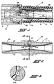
- Fig. 1 is a cross sectional view of the hose coupling of the present invention in a coaxial vapor recovery hose assembly as connected to a dispensing nozzle.
- Fig. 2 is a cross sectional view of the hose coupling of the present invention.
- Fig. 3 is a cross sectional view taken along line 3-3 of Fig. 2.
- Fig. 1 illustrates a coaxial vapor recovery hose assembly shown generally at 10 having an inner product hose 12 with the arrows 13 indicating the fuel product flow path. Coaxially surrounding the product hose 12 is the outer hose 14 which together with the product hose 12 defines an annular vapor passageway 15 therebetween, with the arrows within the passageway indicating the flow of vapors back to the pump stand (not shown).
- the hose assembly is illustrated as being connected to the product dispensing nozzle 16 by means of an outer hose fitting 18 and product hose coupling 20.
- the inner hose coupling of the present invention can also be utilized at the inlet end of the product hose at the pump stand but would be subject to the disadvantage alluded to above of requiring extra lift to remove liquid accumulations from the low point in the catenary of the hose.
- the hose coupling 20 has a generally cylindrically shaped outer surface and a venturi-shaped inner surface with a throat area 21.
- the hose coupling 20 has at least one aspirator port 24 communicating between the throat area 21 and at least one chamber 25 bored in the outer surface.
- Fig. 1 illustrates a hose coupling 20 with one aspirator port 24 while
- Fig. 2 illustrates a hose coupling 20 having a plurality of aspirator ports 24a and 24b.
- Each chamber 25 has associated therewith a check valve 22 which prevents the flow of product from the product hose into the annular vapor passageway.
- an elbow fitting 26 which extends from each chamber 25 and is connected to an outlet end of a suction tube 28.
- the inlet end of the suction tube 28 extends through the vapor passageway 15 to a low point in the catenary (not shown) of the hose assembly while the hose assembly is in use. It will be appreciated that a filtration device should be used at the suction tube inlet.
- a plurality of barb-like ridges 27 on the outer surface of the hose coupling 20 which is inserted within the product hose 12, and the two are held securely and sealingly together by a crimped ferrule or band 29.
- the other end of the hose coupling 20, away from the ridges 27, is characterized by an outer peripheral surface 30 which sealingly engages the product conduit 31 of the dispensing nozzle 16.
- the product flowing in the product hose 12 through a flow path 13 into the hose coupling 20 causes a pressure drop across the venturi throat 21 creating a suction through the aspirator port 24, the elbow fitting 26 and suction tube 28 to remove any liquid accumulation at the inlet end of the suction tube 28 which is located in the low point of the catenary of the hose while the hose assembly is in use
- the hose assembly of the present invention be used with a hose rotation restrainer such as is disclosed and claimed in US-A-5,082,027.
- Such a hose restrainer is attached to the product hose at the low point in the catenary of the hose assembly, along with the inlet end of the suction tube 28 to affix the end of the suction tube in the vapor passageway 15 beneath the product hose 12 and to prevent rotation of the product hose 12 in order to maximize the removal of liquid accumulations.
Landscapes
- Engineering & Computer Science (AREA)
- Mechanical Engineering (AREA)
- Loading And Unloading Of Fuel Tanks Or Ships (AREA)
- Rigid Pipes And Flexible Pipes (AREA)
- Treatment Of Fiber Materials (AREA)
- Cleaning In General (AREA)
Claims (4)
- Assemblage coaxial de tuyaux flexibles pour la récupération de vapeur, comportant :- un tuyau flexible interne (12) destiné au produit, un tuyau flexible externe (14) relié à une tuyère (16) d'alimentation du produit au moyen d'un raccord externe (18) pour tuyaux flexibles et entourant coaxialement ledit tuyau flexible (12) destiné au produit de façon à définir entre eux un passage annulaire (15) destiné à la vapeur;- un tube d'aspiration (28) dans ledit passage (15) comportant une extrémité d'entrée s'étendant jusqu'à un point inférieur dans le caténaire de l'assemblage de tuyaux flexibles lors de la mise en service, ainsi qu'une extrémité de sortie; et- un raccord (20) pour tuyaux flexibles comportant une première extrémité et une seconde extrémité, comprenant :
une surface interne en forme de Venturi munie d'une zone de col (21);
au moins un orifice d'aspiration (24) mettant en communication ladite zone de col (21) et au moins une chambre (25) forée dans la surface externe dudit raccord (20) pour tuyaux flexibles;
une soupape de réglage (22) associée à chaque chambre (25),
la surface périphérique externe (30) de la seconde extrémité dudit raccord (20) venant se mettre en contact d'étanchéité avec le conduit (31) de la tuyère d'alimentation (16) destiné au produit,
caractérisé- en ce que ladite surface externe dudit raccord (20) pour tuyaux flexibles est de forme généralement cylindrique,- en ce qu'on trouve plusieurs nervures (27) en forme de barbes sur ladite surface externe à la première extrémité dudit raccord (20), insérées dans une première extrémité dudit tuyau flexible (12) destiné au produit,- en ce que ladite soupape de réglage (22) est disposée dans chaque chambre (25), et- en ce qu'un raccord coudé (26) s'étend à partir de chaque chambre (25) et est relié à ladite extrémité de sortie dudit tube d'aspiration (28). - Assemblage coaxial de tuyaux flexibles pour la récupération de vapeur selon la revendication 1, caractérisé en ce que le tuyau flexible (12) destiné au produit est maintenu sur les nervures (27) en forme de barbes à l'intervention d'une virole ou d'une bande sertie (29).
- Assemblage coaxial de tuyaux flexibles pour la récupération de vapeur selon la revendication 1, caractérisé en ce qu'on utilise un dispositif de filtration à l'entrée du tube d'aspiration (28).
- Assemblage coaxial de tuyaux flexibles pour la récupération de vapeur selon la revendication 1, comprenant un dispositif d'antirotation du tuyau flexible, ainsi qu'un moyen de fixation pour fixer ledit dispositif de retenue et ladite extrémité d'entrée du tube d'aspiration au tuyau flexible destiné au produit audit point inférieur.
Applications Claiming Priority (2)
| Application Number | Priority Date | Filing Date | Title |
|---|---|---|---|
| US42103389A | 1989-10-13 | 1989-10-13 | |
| US421033 | 1989-10-13 |
Publications (2)
| Publication Number | Publication Date |
|---|---|
| EP0423060A1 EP0423060A1 (fr) | 1991-04-17 |
| EP0423060B1 true EP0423060B1 (fr) | 1994-01-05 |
Family
ID=23668918
Family Applications (1)
| Application Number | Title | Priority Date | Filing Date |
|---|---|---|---|
| EP19900630174 Expired - Lifetime EP0423060B1 (fr) | 1989-10-13 | 1990-10-10 | Raccord pour tube combiné avec pompe à jet |
Country Status (6)
| Country | Link |
|---|---|
| EP (1) | EP0423060B1 (fr) |
| CA (1) | CA2019030C (fr) |
| DE (1) | DE69005778T2 (fr) |
| FI (1) | FI95904C (fr) |
| IE (1) | IE70299B1 (fr) |
| NO (1) | NO178184C (fr) |
Families Citing this family (2)
| Publication number | Priority date | Publication date | Assignee | Title |
|---|---|---|---|---|
| DE102006035033A1 (de) * | 2006-07-28 | 2008-01-31 | GM Global Technology Operations, Inc., Detroit | Venturidüse |
| BR112019005619A2 (pt) | 2016-09-21 | 2019-06-18 | Dayco Ip Holdings Llc | válvula de gaveta interna a uma abertura de venturi de um dispositivo de venturi para a produção de vácuo |
Family Cites Families (3)
| Publication number | Priority date | Publication date | Assignee | Title |
|---|---|---|---|---|
| DE2909988A1 (de) * | 1978-03-20 | 1979-10-04 | Atlantic Richfield Co | Vorrichtung zur abgabe von fluessigkeiten, beispielsweise treibstoffen, und zur gesteuerten fuehrung des hierbei anfallenden dampfes |
| CA1276917C (fr) * | 1984-03-15 | 1990-11-27 | Roger W. Furrow | Systeme extracteur de liquide d'un tube garni d'un bec verseur pour empecher la naissance de tampons liquides dans la voie de recuperation des vapeurs |
| EP0412082A1 (fr) * | 1987-09-18 | 1991-02-13 | DAYCO PRODUCTS, Inc. | Assemblage a tuyau et son procede de fabrication |
-
1990
- 1990-06-14 CA CA 2019030 patent/CA2019030C/fr not_active Expired - Fee Related
- 1990-10-08 IE IE358890A patent/IE70299B1/en not_active IP Right Cessation
- 1990-10-10 DE DE1990605778 patent/DE69005778T2/de not_active Expired - Fee Related
- 1990-10-10 EP EP19900630174 patent/EP0423060B1/fr not_active Expired - Lifetime
- 1990-10-11 NO NO904405A patent/NO178184C/no not_active IP Right Cessation
- 1990-10-12 FI FI905024A patent/FI95904C/fi not_active IP Right Cessation
Also Published As
| Publication number | Publication date |
|---|---|
| DE69005778D1 (de) | 1994-02-17 |
| FI95904B (fi) | 1995-12-29 |
| FI905024A0 (fi) | 1990-10-12 |
| NO178184B (no) | 1995-10-30 |
| NO178184C (no) | 1996-02-07 |
| NO904405L (no) | 1991-04-15 |
| DE69005778T2 (de) | 1994-06-30 |
| NO904405D0 (no) | 1990-10-11 |
| IE70299B1 (en) | 1996-11-13 |
| IE903588A1 (en) | 1991-04-24 |
| CA2019030A1 (fr) | 1991-04-13 |
| CA2019030C (fr) | 2000-10-31 |
| EP0423060A1 (fr) | 1991-04-17 |
| FI95904C (fi) | 1996-04-10 |
Similar Documents
| Publication | Publication Date | Title |
|---|---|---|
| EP0326842B1 (fr) | Dispositif de distribution de carburant | |
| US4687033A (en) | Venturi liquid evacuator system for maintaining clear vapor path in vapor recovery hose | |
| US4842027A (en) | Vapor passage fuel blockage removal | |
| US4749009A (en) | Vapor passage fuel blockage removal | |
| EP0274599B1 (fr) | Dispositif d'aspiration de carburant liquide comportant un venturi et des conduits de déviation | |
| US4566504A (en) | Insertion tube liquid evacuator system for vapor recovery hose | |
| US4967809A (en) | Vapor passage fuel blockage removal | |
| US4090539A (en) | Anti-pollution service station assembly | |
| US5628344A (en) | Dry disconnect coupling including means for returning fluid residue to flow path | |
| US5040576A (en) | Vapor passage fuel blockage removal | |
| US5207898A (en) | Filter head with integral priming pump and valved bypass passage | |
| US3952781A (en) | Liquid dispensing and vapor recovery system and a vapor flow control unit used therein | |
| EP1237813A4 (fr) | Indicateur coaxial de flux de vapeur a commande de vitesse de la pompe | |
| US5913336A (en) | Gasoline dispensing hose | |
| US3941168A (en) | Liquid dispensing and vapor recovery system utilizing an injector and a vapor flow control valve | |
| US4256151A (en) | System for dispensing a volatile fuel | |
| US6360789B2 (en) | Vapor recovery line diagnostics | |
| CN1646416A (zh) | 具有数据接口的连接器 | |
| US5129433A (en) | Vapor passage fuel blockage removal | |
| US5240045A (en) | Vapor passage fuel blockage removal | |
| US20020008162A1 (en) | High pressure hydraulic cleaning unit possibly with detergent ejector device | |
| US5782579A (en) | Pipe system for supplying liquid fuel to an underground tank and for transfer of such fuel to a dispensing station | |
| US5351727A (en) | Fuel dispensing system, hose assembly therefor and methods of making the same | |
| CA2019030C (fr) | Raccord de tuyau flexible et pompe d'aspiration combines | |
| US5520228A (en) | Fuel extraction coupling for nozzle |
Legal Events
| Date | Code | Title | Description |
|---|---|---|---|
| PUAI | Public reference made under article 153(3) epc to a published international application that has entered the european phase |
Free format text: ORIGINAL CODE: 0009012 |
|
| 17P | Request for examination filed |
Effective date: 19901022 |
|
| AK | Designated contracting states |
Kind code of ref document: A1 Designated state(s): DE FR GB IT SE |
|
| 17Q | First examination report despatched |
Effective date: 19920227 |
|
| GRAA | (expected) grant |
Free format text: ORIGINAL CODE: 0009210 |
|
| AK | Designated contracting states |
Kind code of ref document: B1 Designated state(s): DE FR GB IT SE |
|
| REF | Corresponds to: |
Ref document number: 69005778 Country of ref document: DE Date of ref document: 19940217 |
|
| ET | Fr: translation filed | ||
| ITF | It: translation for a ep patent filed | ||
| PLBE | No opposition filed within time limit |
Free format text: ORIGINAL CODE: 0009261 |
|
| STAA | Information on the status of an ep patent application or granted ep patent |
Free format text: STATUS: NO OPPOSITION FILED WITHIN TIME LIMIT |
|
| 26N | No opposition filed | ||
| EAL | Se: european patent in force in sweden |
Ref document number: 90630174.2 |
|
| REG | Reference to a national code |
Ref country code: GB Ref legal event code: IF02 |
|
| PGFP | Annual fee paid to national office [announced via postgrant information from national office to epo] |
Ref country code: GB Payment date: 20020913 Year of fee payment: 13 |
|
| PGFP | Annual fee paid to national office [announced via postgrant information from national office to epo] |
Ref country code: FR Payment date: 20021003 Year of fee payment: 13 |
|
| PGFP | Annual fee paid to national office [announced via postgrant information from national office to epo] |
Ref country code: SE Payment date: 20021004 Year of fee payment: 13 |
|
| PGFP | Annual fee paid to national office [announced via postgrant information from national office to epo] |
Ref country code: DE Payment date: 20021031 Year of fee payment: 13 |
|
| PG25 | Lapsed in a contracting state [announced via postgrant information from national office to epo] |
Ref country code: GB Free format text: LAPSE BECAUSE OF NON-PAYMENT OF DUE FEES Effective date: 20031010 |
|
| PG25 | Lapsed in a contracting state [announced via postgrant information from national office to epo] |
Ref country code: SE Free format text: LAPSE BECAUSE OF NON-PAYMENT OF DUE FEES Effective date: 20031011 |
|
| PG25 | Lapsed in a contracting state [announced via postgrant information from national office to epo] |
Ref country code: DE Free format text: LAPSE BECAUSE OF NON-PAYMENT OF DUE FEES Effective date: 20040501 |
|
| EUG | Se: european patent has lapsed | ||
| GBPC | Gb: european patent ceased through non-payment of renewal fee |
Effective date: 20031010 |
|
| PG25 | Lapsed in a contracting state [announced via postgrant information from national office to epo] |
Ref country code: FR Free format text: LAPSE BECAUSE OF NON-PAYMENT OF DUE FEES Effective date: 20040630 |
|
| REG | Reference to a national code |
Ref country code: FR Ref legal event code: ST |
|
| PG25 | Lapsed in a contracting state [announced via postgrant information from national office to epo] |
Ref country code: IT Free format text: LAPSE BECAUSE OF NON-PAYMENT OF DUE FEES;WARNING: LAPSES OF ITALIAN PATENTS WITH EFFECTIVE DATE BEFORE 2007 MAY HAVE OCCURRED AT ANY TIME BEFORE 2007. THE CORRECT EFFECTIVE DATE MAY BE DIFFERENT FROM THE ONE RECORDED. Effective date: 20051010 |